1
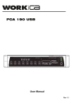
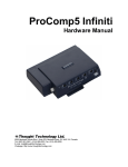
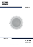
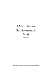
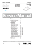
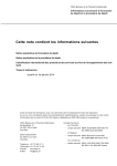
SERVICE MANUAL
CHASSIS CTS-AA
CONTENTS
Page
1.- Technical specifications
2.- Connection Facilities
3.- Mechanical instructions
4.- Oscillograms
5.- Print board layout
6.- Electric Scheme
7.- Circuit description
7.1 Small signal processing
7.2 RGB ampliers
7.3 Deflection
7.4 Sound amplifier
7.5 Power supply
7.6 Microcontroller/Text
8.- Electrical adjustments
9.- Safety instructions
10.- List of abbreviations
11.- Service components
3
3
4
5
6
7 - 11
12
12
14
14
15
15
17
18
21
22
23
2
1. Technical specifications
CHASSIS CTS - AA
Mains voltage
Power cons. at 220V~
Aerial input impedance
Min. aerial input VHF
Min. aerial input UHF
Max. aerial input VHF/UHF
Pull-in range colour sync.
Pull-in range horizontal sync.
Pull-in range vertical sync.
Picture tube range
: 220 - 240 V ± 10% AC; 50 Hz (±5%)
: 35W (14''), 50W(20''/21''), 5W (stand by)
: 75S - coax
: 30µV
: 40µV
: 180mV
: ± 300Hz
: - 600 Hz / + 480 Hz
: ± 5 Hz
: 14'' / 20'' /21''
: Mono: 25S 1W (14''). 16S 2W (20''/21'')
TV Systems
: PAL BG
: PAL I
: PAL BG / SECAM BGDK
: PAL BGI / SECAM BGLL'
Indications
VCR programs
: On screen display (OSD) / menu
: 1 LED RED. Dark in ON, bright in stand by,
blinking with RC.
: 0 to 99
Tuning and operating system
:
UV1315A / IEC (VST)
: VHFa: 48 - 168 MHz
: VHFb: 175 - 447 MHz
: UHF: 455 - 855 MHz
U1343A / IEC (VST)
: UHF: 471 - 855 MHz
Local operating functions
: Vol/Prog, +, -, contrast, colour and brightness.
VST
2. Connection facilities
Euroconector:
1
2
3
4
5
6
7
8
9
10
-
Audio
Audio
Audio
Audio
Blue
Audio
Blue
CVBS status 1
Green
11 - Green
12
13
14
15
16
-
Red
Red
RGB status
R (0V5 RMS / 1K ).
R (0V2 - 2V RMS / 10K ).
L ( 0V5 RMS / 1K ).
17
18
19
20
21
-
CVBS
CVBS
CVBS
CVBS
( 1Vpp 75S ).
( 1Vpp/75S ).
Earthscreen.
L (0V2 - 2V RMS / 10K ).
(0V7pp/75S ).
(0-2V int., 10-12V ext.).
(0V7pp/75S ).
Head phone:
(0V7pp/75S ).
(0V to 0V4 int.) (1-3V ext. 75S ).
3
8S to 600S (32S 25mW)
3. Mechanical instructions
For the main carrier two service positions are possible (3.1).
A: For faultfinding on the component side of the main carrier.
B: For (de) soldering activities on the copper side of the main carrier.
Position A can be reached by first removing the mains cord from it's fixation, then loosen the carrier lips (1) and then pulling the
carrier panel (2) for approximately 10cm.
Position B can be reached from position A after disconnecting the degaussing cable. Put the carrier on the line transformer side.
Fig. 3.1
4
4. Oscillograms
5
5.- PRINT BOARD LAYOUT
6
6.- Electric Diagram
1015
1032
1033
1137
1272
2010
2011
2013
2014
2015
2016
2017
2018
2024
2025
2026
2027
2028
2029
2034
2060
2061
2064
2065
2067
2068
2115
2117
2180
2185
2240
2242
2243
2244
2245
2250
2261
2262
2270
2289
2291
2292
2293
2294
2350
2351
2801
2861
3010
3011
3012
3017
3018
3019
3020
3021
3028
3032
3033
3034
3035
3069
3070
3115
3117
3118
3119
3120
3121
3185
3240
3262
3274
3275
3276
7
D6
G8
F8
B7
H3
D7
D7
D8
D8
H6
H6
E9
E7
C6
D6
C6
C6
E6
E6
I7
F7
F6
F3
F3
C3
C3
B6
B9
B3
B3
K7
J2
J2
J2
M2
J6
H3
H2
I3
F3
L7
L7
K7
J7
D3
D3
I7
F8
D7
C7
D7
E8
E8
E8
E8
E8
E7
G7
I7
I7
G8
D2
D2
B6
B8
B8
B8
C8
C8
C3
K6
H3
K3
K2
L3
3281
3284
3285
3286
3287
3288
3289
3291
3294
3330
3331
3335
3346
3351
3371
3372
3373
3715
5010
5012
5032
5040
5060
5067
6014
6020
6115
7015
7127
7274
7275
7276
7372
9001
9002
9003
9004
9006
9007
9008
9009
9010
9012
9013
9014
9016
9018
9019
9020
9021
9022
9023
9174
9200
9201
9561
9656
F3
K2
K2
L2
K2
K3
K3
K3
L3
E2
F2
H2
E3
D3
E3
D2
E2
F8
D8
D8
F8
H7
F7
C2
C8
E8
B8
G5
C8
K3
L3
L3
D2
A2
G3
M6
E7
G2
E3
E2
D2
A2
M9
M9
M8
A3
B2
B2
M6
M6
M7
M8
M5
B2
M7
A2
E3
6.- Electric Diagram
2204
2208
2209
2217
2230
2402
2403
2404
2405
2406
2407
2408
2410
2411
2430
2440
2442
2444
2445
2446
2448
2449
2450
2451
2453
2458
2460
2462
2470
3201
3202
3203
3204
3208
3210
3211
3212
3214
3215
3216
3217
3221
3225
3226
3228
3229
3230
3233
3234
3235
3238
3243
3244
3400
3401
3402
3403
3404
3405
3406
3407
3408
3409
3410
3411
3412
3413
3414
3416
3417
3418
3430
3431
3432
8
C6
E3
D3
D6
F6
G7
H6
I8
I7
I5
H5
K7
H4
I4
H3
M6
M6
L6
L5
L4
K5
K5
L7
L6
M2
J4
K3
L3
K5
A5
A6
B4
B6
B6
B7
D7
E7
C5
C6
C5
D6
D6
E6
E3
D3
E5
E6
D5
D6
L4
M4
E5
E6
G8
I8
H7
H7
I7
I7
H6
H5
I6
I6
H6
I7
I7
I5
I5
I4
I4
H5
G4
H4
G4
3433
3434
3440
3442
3444
3445
3449
3451
3455
3456
3457
3460
3461
3462
3463
3470
3480
5201
5202
5440
5441
5445
5447
5449
5480
6201
6218
6225
6227
6243
6401
6447
6449
6451
6462
6470
7201
7204
7205
7208
7209
7210
7211
7212
7213
7401
7430
7431
7440
7445
9204
9212
9214
9217
9220
9221
9401
9402
9404
9417
9480
G3
H3
M7
M6
L7
L5
M3
L6
K7
K6
J5
K3
K4
K3
H2
K4
L6
D4
D4
M7
L6
L4
J4
M3
L6
A5
C5
F6
D5
F5
H5
L4
M3
L6
H2
K5
A5
B5
B6
C5
C5
C6
D5
E5
E6
G6
G4
G3
M6
L5
B5
E5
D7
E7
E7
C7
G5
H7
I6
I5
K6
6.- Electric Diagram
1001
2001
2002
2005
2006
2090
2091
2092
2179
2182
2184
2186
2187
2188
2189
2190
2191
2192
2194
2195
2197
2800
2850
2852
2856
2857
2859
2860
2876
3000
3002
3003
3004
3005
3006
3007
3008
3026
3186
3187
3190
3191
3193
3194
3197
3808
3809
3810
3841
3843
3845
3850
3851
3852
3853
3854
3855
3856
3858
3860
3865
3875
3876
3877
3879
3880
3881
3883
3891
3893
5061
6848
6849
6851
9
B7
B8
B6
D7
C7
C8
D8
D8
K3
K3
K4
L6
G7
G7
K6
G7
K6
H7
H6
K6
L6
F2
F3
E3
E2
F4
F2
F4
B4
D8
C9
C8
C9
C8
D9
D8
D8
D8
K5
L6
G8
H7
I6
I5
I6
F3
E4
E2
E5
D5
C5
F2
E3
E2
D3
E2
C3
F2
C3
E4
B2
B4
C4
B4
D2
E2
D1
E1
C2
G3
B7
C2
B2
E4
6852
6853
6854
6855
6856
6857
7187
7187
7875
7876
9102
9143
9169
9170
9181
9182
9190
9801
9802
E4
D4
D4
D4
D4
D5
J4
K6
B5
D2
L6
J3
H7
H5
H5
L4
G8
B4
F2
6.- Electric Diagram
1500
1540
1541
2500
2502
2503
2504
2505
2506
2507
2508
2509
2510
2511
2514
2515
2516
2522
2523
2524
2530
2532
2534
2540
2561
2562
2563
2564
2565
3500
3501
3502
3503
3504
3505
3507
3508
3509
3510
3512
3516
3517
3518
3519
3520
3521
3522
3523
3524
10
C1
I4
H2
D2
F2
E2
F2
F2
H5
E2
F4
D4
D4
E4
F3
F4
G2
G3
E3
G3
I2
H4
H2
I4
K2
J2
K4
I3
I3
G2
E2
J4
L4
B2
K5
F2
E4
C4
D4
F4
G2
F4
E4
D3
D2
G3
G3
F3
C2
3525
3527
3528
3570
3571
3573
3574
3575
3576
3577
5500
5525
5531
5532
5534
5540
5552
6502
6503
6504
6505
6515
6516
6521
6530
6540
6541
6570
6571
6572
6573
6574
7501
7502
7514
7525
7571
7575
7577
9501
9503
9506
9523
9524
9541
9570
9582
9598
9599
C3
G4
G4
J3
K3
K3
I3
J5
J3
I3
D2
H3
J2
H4
H2
K4
G2
F2
F2
F2
F2
F4
G2
F3
I2
H4
H2
J3
J3
J4
I3
K4
J5
J4
E3
G3
J3
J2
I2
K2
B1
E5
E3
D4
I5
J3
K5
C2
C1
6.- Electric Diagram
1679
1685
2149
2600
2602
2610
2611
2636
2641
2648
2651
2660
2669
2677
2680
2681
2682
2685
2691
2692
3149
3601
3602
3603
3604
3605
3606
3607
3608
3609
3610
3611
3612
3616
3617
3618
3619
3620
3621
3636
3637
3643
3644
3645
3646
3647
3648
3649
3650
3651
3652
3653
3656
3657
3658
3659
3660
3661
3662
3663
3664
3665
3666
3667
3668
3669
3670
3673
3674
3675
3676
3681
3684
3685
11
G3
F2
E2
D3
C7
D7
D8
K7
K3
L7
B3
F2
I2
H3
G3
G3
F3
F2
F3
F8
E3
B8
B8
C7
C7
C7
C6
C6
E7
F7
C7
C8
C8
D2
E2
F7
G7
F6
D7
L7
K7
K3
J3
J3
J3
K3
L7
J3
J4
J4
I3
K4
E3
E3
E3
E3
F2
I7
F3
J7
J8
G8
J7
G8
I2
I2
I3
I8
J8
K8
F3
I7
D3
D3
3687
3691
3692
3696
6149
6602
6663
6691
7600
7605
7657
7659
7670
7673
7685
7691
9504
9607
9652
9674
9675
9678
9679
9685
9696
K3
B2
B2
J8
E3
C7
J7
C2
H5
C7
E2
E2
I3
I8
D3
B2
B8
L2
I3
L8
L8
L2
M2
L2
B8
STV2246:
STV2248:
Figure 7.1 TV Processor block diagram
7.- CIRCUIT DESCRIPTION
7.1 SMALL SIGNAL PROCESSING (Diagram A)
The small signal is processed by IC 7015 (STV2246 for Pal sets, STV2248 for Pal/Secam sets), including IF detection,
video processing, chroma decoder, RGB , sync processor and sound decoder. The ICs STV2246 and STV2248 are fully
controlled by I2C bus and their block diagram can see in fig. 7.1.
7.1.1 IF detection
IF detection can be intercarrier (no multistandard sets), that means sound and picture are detected in the same circuit
(PIF), or QSS (Quasi Split Sound, used in multistandard sets) where sound is detected in a separated circuit (SIF).
- PIF input (pins 6, 7): The IF signal coming from pin 11 of the tuner (diagram C) is filtered by the IF SAW filter (1015) and
applied to PIF input of IC7015 (pins 6 and 7). The IF bandpass characteristic is determined by the SAW (Surface
Acoustic Wave) filter.
- PIF oscillator (pins 9, 15, 16): The PIF PLL (phase locked loop) is based on a LC resonator (L5040). Carrier frequency
should be adjusted by I2C bus at 38.9 MHz (see chap. 8.3). A filter for the PLL is present at pin 9 (2028, 2029, 3028).
AFC is internally controlled for the µC (7600 diagram E) by I2C. Identification signal is also internal.
- AGC (pins 5, 8): The IF AGC time constant is fixed by the capacitor 2025 (pin 5). The AGC delayed voltage (pin 8) is
applied to pin 1 of the tuner and adjusted by I2C (see chap. 8.4).
- Video output (pin 13) : This baseband CVBS signal with 2Vpp of nominal amplitude, contains the FM intercarrier sound
signal. Sound is filtered out by a ceramic trap (1032 or 1033) which frequency can be different depending on the system:
5.5 MHz for BG, 6.0 MHz for I or 6,5 MHz for DK.
Multistandard sets
- The IC STV2248 is used in multistandard sets.
- Only picture IF is processed in PIF circuit (pins 6,7), and carrier frequency has a second adjustment (by I2C) at
33.9MHz for L’ standard (see chap. 8.3). The IC changes automatically between negative (BGIDK) and positive
(LL’) modulation.
- Sound IF is processed in SIF circuit (QSS system)
- SIF input (pins 1, 2): Sound is filtered from IF signal in a SAW filter K9650 (1137). The IF input is present at pin
1 of 1137 and pin 2 is used as a switching input:
- If Vpin2 = 0V a 40.40MHz sound carrier is filtered (for L´ system, L/L´ signal is high, T7127 conducts).
- If Vpin2 = Vpin1 a 33.40MHz sound carrier is filtered (for L,I,BG systems, L/L´ signal is low, T7127 is cut,
D6115 conducts).
- SIF AGC (pin 3): The sound IF AGC time constant is fixed by the capacitor C2024.
7.1.2 Sound processor
- FM demodulation: For intercarrier sets (no multistandard) FM sound is filtered internally from CVBS (pin 13) and
demodulated. De-emphasis is also made internally. If the set is Pal/Secam BG or DK, STV2248 is used instead of
STV2246. SIF input and AM demodulator are avoided and pins 1, 2 are AC grounded by C2115.
- Scart audio out (pin 11): The signal at this pin is drived to the euroconnector sound outputs (see Diagram C).
- External audio in (pin 14): External audio proceeding of pins 2,6 of euroconnector is applied to this pin. Selection
between internal or external is done by an internal switching controlled by I2C (see INT/EXT, chapter 7.6).
- Audio out (pin 55): After a volume control (by I2C), this output is drived to the input IN+ of the final sound amplifier IC7187
(Diagram C).
Multistandard sets:
FM demodulation: This function is done in the same internal circuit of STV2248 that no multi sets, but the input
proceeds of SIF circuit, instead of CVBS signal.
AM demodulation: In Multistandard sets, also AM demodulation for LL’ systems is necessary. AM sound is
extracted directly from the SIF inputs by an internal circuit.
AM/FM switch : This internal switch is commanded by the µC depending on the system selected on the tuning
menu.
7.1.3 Video processing
- Video switches (pins 18, 20, 44): The internal CVBS signal is now fed to pin 18 IC7015. External CVBS proceeding
from pin 20 of Euroconnector is present on pin 20 of 7015. The IC switches between internal and external by I2C bus (see
INT/EXT, chapter 7.6). At pin 44 there is an output of CVBS used for the TXT decoder.
12
- Luminance processor: CVBS coming from video switches is internally applied to luminance processor, which is composed
of chrominance trap filter, luminance delay line and peaking circuits. Sharpness control modifies peaking by I2C.
- Black stretch circuit (pin 21): This feature of the picture is fixed (not adjustable). Black stretch capacitor 2250 is
connected to pin 21.
7.1.4 Chroma Decoding
- ACC and chroma filter: Video signal coming from video switches, goes through an internal variable-gain amplifier to the
chroma band pass filter. Gain of amplifier is determined by burst amplitude (ACC). If the amplitude of chroma signal is
higher than standard, an additional overload circuit decreases it (ACCO).
- XTAL (pin 40): The VCO uses one 4,43MHz crystal connected to pin40.
PAL sets:
STV2246 is used. Bandpass filter and demodulator are fully integrated.
Demodulator consist of synchronous detectors.
PLL is locked during the burst gate time window.
- CLPF (pin 41): The voltage on this chroma PLL filter controls the VCO in order to have the right frequency and
phase according burst signal.
PAL/ SECAM sets:
STV2248 is used. Pal or Secam signals are recognized automatically by the IC.
Pal decoding is the same as in STV2246.
Secam demodulation is based on a PLL with automatic calibration loop.
- Secam bell filter (pin 38): Central frequency of bell filter (4.286 MHz) is fine tuning during frame blanking, using
the XTAL frequency (4.433 MHz) as a reference. Tuning control voltage is stored in C2270.
- Chroma DL: The outputs of the demodulator are applied to an internal chroma delay line. Line number n is delayed
64useg and added to n+1 obtaining U and V signals (R-Y and B-Y).
7.1.5 RGB processor
- External RGB inputs (pins 25, 26, 27): RGB inputs coming from scart (see diagram C), are AC coupled (C2291/92/93)
and converted internally in YUV signals (RGB TO YUV). Then are switched with internal YUV (YUV SWITCH) by fast
blanking.
- Fast blanking external (pin 28): When fast blanking is high external RGB is displayed, only if TV is in external AV
(program 0). Fast blanking can switch signals for full screen (by a DC voltage) or for a part of the screen (by a pulse
voltage).
- Matrix: After switching, YUV signals are converted to RGB in the internal MATRIX circuit. Saturation control is received
from the µC by I2C bus.
- APR (pin 24): The APR circuit (Automatic RGB Peak Regulation) compensates the spread of contrast between sources.
If one of RGB signals exceeds the APR threshold, 2440 is charged and the gain is decreased. APR threshold can be
adjusted in Service menu.
- RGB OSD (pins 36, 35, 34): RGB inputs for OSD and TXT coming from µC (7600 diagram E), are AC coupled (C2242/
43/44) and applied to a RGB SWITCH controlled for the µC by fast blanking input (pin 37).
Video controls: Contrast, brightness and saturation are adjusted by I2C for the µC.
- BCL input (pin 46): Beam current is limited by circuit BCL/SAF. When beam current is high, voltage of C2460 is lower
(Diagram B), D6462 conducts and Vpin46 is lower. When Vpin46 < 5.75V first contrast and then brightness are reduced.
- Safety input (pin 46): BCL/SAF circuit has also a safety function. If frame deflection is broken down, T7431 conducts
(Diagram B), Vpin46 = 0V and line deflexion (pin 48) is disabled .
- RGB output circuit (pins 32, 31, 30): RGB outputs are drived to RGB amplifier (Diagram B).
- Digital cut-off loop (pin 33): Cut-off loop permits to control automatically the cut-off point of the 3 RGB cathodes by DC
level. At the end of the frame blanking 3 consecutive cut-off lines, B, G and R are created. Cut-off current flows across
T7204, T7209 and T7212 (Diagram B) respectively and it is measured on pin 33. When VG2 voltage is adjusted, DC level
of RGB outputs is adapted to keep cut-of current.
- Warm-up detection circuit (pin 33): At the start up picture is blanked and 3 white lines are drived, instead of cut-off lines.
As soon as the start beam current is detected on pin 33, RGB circuit starts in normal operation. If RGB circuit is
damaged or grid 2 is low, the RGB circuit could not start (black picture) due to current is not detected.
7.1.6 Horizontal synchro
- Start up (pins 45, 53): The horizontal oscillator starts running when supply voltage of pin 45 reaches 6V and supply
voltage of pin 53 reaches 4V. During start up circuit provides a softer operating horizontal output with a 75% of duty cycle.
13
Note: The set do not start up if protection voltages are activated (Vpin 49 > 2.5V or Vpin46 < 1V)
- Hor. sync. separator: Fully integrated sync. separator with a low pass filter, slicing level at 50% of the synchronized
pulse amplitude.
- Horizontal 1st loop circuit (pin 50): The first phase locked loop (PLL1) locks the internal line frequency reference on the
CVBS input signal. It is composed of an internal VCO (12MHz) that requires the chroma reference frequency (4.43MHz
at pin 40), a divider by 768, a line decoder and a phase comparator. Scanning PLL1 filter (SLPF) needs external components
on pin 50. PLL1 time constant is automatically controlled by software for broadcasting signals. For video signals (AV and
program 99) constant is always fast to prevent top bending on the screen.
- LBF (pin 49): Line Fly Back input, is obtained by the network R3456/55 (Diagram B), T7372 and R3371. Output of T7372
is used also as HSYNC of the µC (pin 36 IC7600 diagram D). When the DC voltage of pin 49 is higher than 2.5V, HOUT
(pin 48) is inhibited (protection).
- SSC output (pin 49): Super Sand Castle output is used only internally. Levels of sandcastle pulse are 5V for burst
detection, 3V for line blanking and 2V for frame blanking.
- Horizontal 2nd loop circuit: The flyback position respect line blanking on TRC cathode is controlled in this circuit. Phase
can be adjusted by I2C.
- HOUT (pin 48): Horizontal output is an open collector which one drives the horizontal driver stage (T7440 diagram B).
7.1.7 Vertical synchro
- Vert. sync. separator: It is an internal integrator to separate frame sync. pulses from CVBS.
- Vertical oscillator: Vertical frequency is obtained internally from line frequency by a line counter. Mode used is automatic
50/60Hz identification with 50Hz priority.
- Vert. output stage (pin 43): This pulse output is used to drive the sawtooth generator in the vertical amplifier (pin 3
IC7400 diagram B) and also as VSYNC of the µC (pin 37 IC7600 diagram D). The VERT pulse period is 314 lines in 50Hz
free running mode (264 in 60Hz) and 312.5 lines in 50Hz synchronized mode (262.5 in 60Hz). Frame blanking is from line
2 to 12.5.
- Vert. amplitude (pin 42): This DC output is applied by a divider resistor (R3416, R3414 diagram B) to pin 4 of IC7400 to
control vertical amplitude. It can be adjusted by I2C from 1.5V (max. vert. amplitude) to 6V (min. vert. amplitude).
7.2 RGB AMPLIFIERS (diagram B)
- RGB inputs : The inputs of RGB amplifiers come from pins 32, 31 and 30 of IC7015 (Diagram A). White D is adjusted
in IC7015 changing the AC level of the inputs by I2C bus and cut-off changing the DC level.
- RGB amplifiers (7205, 7210, 7213): RGB circuit consist of 3 inverter amplifiers (7205, 7210, 7213) including active load
(7201, 7208, 7211). To improve high frequency amplification there are small capacitors (2204, 2217 and 2230), and to
adapt DC level for inputs there is a diode (6225).
- Cut off control (7204, 7209, 7212): Cathode current produced at cut-off pulses, is applied to cut-off control circuit, pin 33
of IC7015 (see 5.1.5), across transistors (7204, 7209, 7212). Diode 6243 is added to prevent high voltage in IC7015.
- Flash-over protections: Clamping diodes to +200V (6201, 6218, 6227) and 1K5 series resistors (3203, 3216, 3326,
3228, 3229) are added for protect the circuit from TRC flash-over.
7.3 DEFLECTION (Diagram B)
7.3.1 Frame deflection
This function is performed by the integrated circuit TDA1771 (7401).
- Frame supply (pins 2, 9, 10): Pin 9 is used to supply the IC except output stage which one is supplied by pin 2. At pin
2 there is a higher voltage during flyback time. This is produced adding the flyback signal present at pin 10 to a +25V
supply by D6401 and C2410.
- Vertical driver (pin 3): A vertical pulse is drived by pin 47 of IC7015. This pulse is used to synchronize vertical oscillator.
- Vertical oscillator (pin 6): Saw tooth is performed in the capacitor 2406. R3417 makes a feed back to stabilize vertical
amplitude from beam current.
- Vertical amplitude (pin 4): A DC voltage originated at pin 42 of IC7015 and adjusted I2C bus is applied to pin 4 to modify
vertical amplitude.
- Vertical output (pin 1): Vertical output is applied to deflection coil. DC current is suppressed by C2404. A voltage
proportional to current deflection is present in R3411/12 and a feedback of it is sent to pin 8 across C2405, R3405 and
R3407. A DC feedback is obtained by resistor divider R3403 and R3404. Linearity is corrected by the network C2405 and
R3405.
- CRT protection (7430, 7431): When frame deflection is broken down, transistor 7430 is cut, and 7431 conducts so that
the signal BCI/SAF=0V and the line is switched off protecting the tube ( see pin 46 of IC7015 ).
14
7.3.2 Line deflection
The final line transistor is driven by the transformer 5441, whose primary winding is driven by the transistor T7440
connected to the line drive output of IC7015 (pin 48).
The horizontal deflection stage is carried out in a conventional way, with the deflection transistor (T7445) and line
transformer (5445).
Beam current info (BCI) is present at C2460.
There are the following supply voltages obtained from line transformer (5545):
+25V : To supply frame deflection..
FF : The heather voltage is reduced by R3235/38 and 5201/02 (Diagram B) to obtain 6.3Veff at the CRT.
7.4 SOUND AMPLIFIER (Diagram C)
Sound amplifier is a Bridge Tied Load (BTL) amplifier short circuit protection, mute and stand by mode.
IC used can be TDA8941 for 14" and 17" models or TDA8943 for 20" and 21" models. TDA8944 is reserved for stereo
models (not explained in this manual).
- Supply (Vcc, SVR): Main supply (Vcc) is taken from +11V of Power Supply (C2540 diagram D). The IC creates
internally a half supply, present in SVR pin and decoupled by 10uF capacitor.
- Sound input (IN+): This amplifier has a differential input (IN+,IN-). Audio input is connected to IN+ decoupled by 220nF
capacitor (C2186) and IN- is decoupled to ground by other 220nF capacitor. To avoid oscillations there is a 1n5 capacitor
connected between both inputs.
- Mode input: This input is commanded by the µC and has three modes depending of the voltage level:
- Standby mode (Vmode=Vcc): Consumption is very low (used during stand by)
- Mute mode (2.5V<Vmode<Vcc): No sound output (used when the set is switched on/off, there is no signal, etc.)
- Operating mode: (Vmode<0.5V): Sound output present (normal operation).
- Sound output (OUT+/OUT-): Amplified sound is drived to the loudspeakers. Headphones output has been connected
in such a way that when headphones are connected, loudspeakers are switched off.
7.5
POWER SUPPLY (Diagram D)
Mains isolated switched mode power supply (SMPS), controlled by IC7514 (TDA4605) in variable frequency mode.
- Switching behaviour: The switching period is divided in on-time, when energy is extracted from the mains into the
primary winding (8-12 of 5525), off-time, when energy in the transformer is supplied to the loads via secondary windings
of 5525 and dead-time when no energy is extracted or supplied.
- Standby mode: Output voltages are present when the set is on stand by, due to standby is done cutting line deflection.
On-time is lower and power consumption is very low.
7.5.1 Primary side
- Degaussing: R3501 is a dual PTC (2 PTC’s in one housing). After switch on set, PTC is cold so low-ohmic and so
degaussing current is very high. After degaussing, PTC is heated so high-ohmic, so in normal operation degaussing
current is very low.
- Rectifier: Mains voltage is filtered by L5500, full wave rectified by diodes D6502-D6505 and smoothed by C2505 (300V
DC for 220V AC mains).
7.5.2 Control circuit (IC7514)
- Start up and supply (pin 6): When the set is switched on, a current via R3507 is applied to pin 6. When C2514 is
charged to 15V, the power supply starts and a current from pin 5 to T7525 is drived. T7525 and starts conduction and a
voltage across transformer windings is built up. The voltage across winding 4-2 is rectified by diode D6521 and used to
supply the IC on pin 6.
- Soft start (pin 7): The capacitor C2523 causes a slow increase of the duration of the output pulse during start up.
- IC output (pin 5): This output drives T7525. R3523 is a fuse resistor to protect IC from short circuits in T7525. D6516
limits the maximum voltage in T7525.
- Start conduction of T7525 (pin 8): A voltage proceeding from winding 4-2 is applied to this pin. The zero crossing
detector recognizes the complete discharge of the energy stored in the transformer core, in addition to a dead time
depending on C2508. This circuit guarantee that T7525 starts conduction at minimum Vds voltage (see fig 7.5).
- Primary current info (pin 2): Current primary winding is simulated by a pin 2 voltage.
- Output voltage info (pin 1): The voltage across winding 4-2 is rectified by diode D6515, divided by R3517, R3518 and
R3508 and applied to pin 1. Internal control voltage (Vcont) inversely proportional to Vpin1 is generated.
15
- Output regulation (pins 1, 2, 8): IC7514 stabilizes output voltage by controlling T-on and so the frequency and the duty
cycle.
Start pulse to T7525 is determined by pin 8 circuit (see fig 7.5).
Then a sawtooth voltage V2 is generated at pin 2. Stop pulse to T7525 is produced when V2 reaches Vcont.
Output control is done by the following way:
If output is higher, V1 is higher, Vcont is lower, T-on and output will be reduced.
If output is lower, output will be increased.
Output voltage of supply can be adjusted by R3518.
Mains voltage variation is stabilized in the following way:
If mains voltage is higher, slope in the sawtooth voltage V2 is higher, stop point is reached before and T-on is
reduced.
If mains voltage is lower, T-on is increased.
7.5.3 Protections
- Overload protection (pin 2): This is produced if T-on is increased till V2 voltage reaches the foldback point (see fig 7.5).
The IC will switch into overload mode (off and on continuously).
- Output voltage protections (pin 6): Limiting values of V6 voltage (7.25V and 16V) provide under and overvoltage protections
for the circuit.
- Mains overvoltage (pin 3): The voltage at pin 3 IC7515 is a measure for the mains voltage and so the DC voltage across
C2505. As soon as the voltage V3 reaches 6.6V, the supply will stop running.
7.5.4 Secondary side
- Line supply:
Line supply present at capacitor C2530 should be adjusted to the correct value (depending on the
TRC) by means of P3518. This supply is also used to obtain +33V varicap voltage by D6602 (see diagram E).
- Sound supply (+11V): This supply is used for sound output amplifier and to feed following stabilizers.
- +8V stabilizer: A reference voltage obtained by a resistor divider R3503 and R3505 is amplified in T7501 and T7502
transistors till diode D6572 conducts stabilizing +8V output. When the set switch to stand by, standby voltage is 0V,
then T7501 is cut, and +8V is reduced to 0V.
- +5V stabilizer: +5V for small signal is made by and D6573 T7577 circuit. R3577 is connected to +8V to switch off +5V
when the set is in stand by mode.
- +5V stand by: +5STB is regulated by T7575 and D6570. A positive power on reset signal (POR) is obtained in the
collector of T7571, which one is cut during start up till R3576 has 0.6V.
Figure 7.5 Power supply signals
16
7.6 MICROCONTROLLER/TEXT (Diagram E)
The CTS-AA chassis is designed to accept 2 different microcontrollers: SAA5531 for TXT models and SAA5541 for no
TXT.
Both microcontrollers are mounted in the same position (7600), and the associated circuitry is the same. The ROM of the
ICs contain an specific program that assures all the functions of the appliance, including 2 menus, one to control the set
(see Instructions Manual) and another for Service Mode (see Service Instruct. chapter 8.1).
The µC for TXT sets contains a teletext decoder, including the following functions: TXT on/off, reveal, freeze, temporary
cancellation, clock, subcode, zoom, index, flof, page +/-, X/26 and 8/30 packet decoding (station identification and startup page).
Following there is an explanation of the different functions of the microcontroller indicating pins number assigned:
- Tuning (pins 1, 9): The unit has a VST (Voltage Synthesized Tuning) system. This system works by tuning to a station
on the tuner through a linear variation of the tuning voltage (V-VARI) from 0V to 33V applied on pin 2 of the tuner. It is
generated on pin 1 of the µC and converted to an adequate level for the tuner using T7605.
While searching, µC are always reading AFC (Automatic Frequency Control) and video identification signals from IC7015
by I2C bus. When video signal is identified, µc stops searching and do a fine tuning to reach a right AFC value.
- Factory facility (pin5): This pin used only in the factory should be connected to +5V by R3621.
- Service (pin 7): This pin is used to put the set in Service Mode (see chapter 8.1).
- INT/EXT input (pin 8): The set can switch to external (AV on the screen) by remote control (selecting program 0) or by
rise edge at pin 8 of euroconnector (see diagram C). The µC switches video and audio (see 5.1.2) to external via I2C bus.
In both cases the user can switch to internal changing the channel.
- Control key (pin 10): Pin 10 is activated by a DC voltage. When control keys are not activated, a voltage of 3V3 is
produced by divider R3618 and R3619. If a control key is activated, a resistor (R3665, R3667) are connected in parallel
with R3619, decreasing the voltage of pin 10. There are 3 voltage levels depending on value of parallel resistor: 1.85V
(910R + 470R), 1V (470R) or 0V (ground circuit).
- Band switching (pin 14, 15, 16): There are 3 outputs for band switching pin 15 for VHFI, pin 16 for VHFIII and pin 14 for
UHF. The µc controls the channel band in the tuner by a voltage of +5V at the correspondent output.
- L/L´ out-put (pin 18): This signal are only used on multistandard units for switching the system in sound filter (see 5.1.5).
L/L’ output is high for L’ system.
- LED (pin 19): The LED (D6663) lights up with a low current when the television set is ON and with a high current when
the set is on Standby. While the set is receiving a remote control signal, the led is blinking.
- Signal I2C bus (pins 20,21): This is a communication bus between the µc and the signal IC (7015).
Picture and sound controls: User controls (brightness, contrast, colour, sharpness and volume) are processed by the µc
and sent to IC7015 by I2C bus. The µc also sends a sound mute when the signal received is interrupted (including
channel search) and a video mute during a change of program.
- Video input (pin 23): CVBS TXT input are only used on TXT sets. The teletext information is extracted from the video
signal inserted on pins 23.
- Standby (pin 30): When this output is low, the set is switched to stand by. Signal voltages of power supply (+5V, +8V
diagram D) are reduced and the line oscillator stops, so there is no signal in pin 48 of IC7015 (diagram A).
- Power supply (pins 31, 39, 44): The IC has several +3V3 power supplies, analog (pin 31), core (pin 39), and POR
periphery ( pin 44 ). All supplies are present during stand by.
- OSD outputs( pins 32, 33, 34, 35): The RGB and fast blanking outputs used for On-Screen Display (OSD) and also for
TXT are applied to RGB inputs of IC7015 (pins 34, 35, 36, 37 diagram A).
- OSD synchronization (pins 36, 37): In order to synchronize the OSD and the TXT information with the picture signal, the
VERT FLYBACK signal (pin 37) and HOR FLYBACK signal (pin 36) are added in inverted form to the integrated circuit.
Due to this if the video signal is lost, the TXT keeps synchronism.
- Oscillator (pins 41, 42): A 12-MHz oscillator is determined by a 12-MHz crystal (1679) between pins 41 and 42.
- P.O.R. (pin 43): Power on reset (POR) is activated when the set is switched on. If the µC shows abnormal behaviour it
is advisable to reset it switching off/on the set. Reset can be produced also connecting pin 43 to +5V for an instant.
- RC5 (pin 45): The commands transmitted by the remote control handset are received by infrared receiver (1685) and
passed to the microcontroller for decoding.
- Mute output (pin 46): This pin is a 3 state output used to control the sound amplifier (see chapter 7.4):
-Stand by mode (Vpin46=0V): T7657 and T7659 are cut, mute signal is 11V
-Mute mode (pin46=open): T7659 conducts (by resistor divider), T7657 are cut, mute is 5,5V.
-Operating mode (Vpin46=3V3): Both transistors conduct, mute signal is 0V.
- EEPROM (pins 49 and 50): The microcontroller is connected to non-volatile memory IC7685 (EEPROM) via bus I2C.
The following information are stored in the memory:
- Channel data including tuning voltage and band of all the channels.
- Personal preferences (PP), menu mix and child lock on user menu.
- All settings included on Service Menu.
17
8.- ELECTRICAL ADJUSTMENTS
8.1 Service mode
The signal processor IC7015 (STV2246 or STV2248) is fully controlled by I2C for the µC IC7600, so that the most of
adjustments of the set can be made by service menu.
- Enter in Service mode: There are 2 ways to enter in Service mode
- By a short circuit between pin 7 of microcontroller ( IC7600 ) and ground while the set is starting up. In this case
all controls (volume, contrast, brightness and saturation) are pre-adjusted to the mid position.
- When the set is in program 75, by pressing at the same time OSD key (+) on RC and MENU key on local key
board during 4 seconds.
Service mode is indicated by a S symbol on the down left corner of the screen.
- Display Service Menu : When the set is in service mode it is possible to display Service Menu by OSD key (+) on
RC. Using P+, P- keys of remote control the different items can be displayed (see table 8.1):
Table 8.1. Service menu. Settings are hexadecimal values
- Pre setting values: When E2PROM is replaced, pre-setting values indicated on table 8.1 are stored by the µC. (see
8.7 E2PROM).
- Adjust by Service Mode: When a item is selected, using V+, V- keys of remote control it can be adjusted. Items 5,
16 and 17 have fixed values = pre setting values, rest of items see 8.2 to 8.7.
- Remove service menu: There are 2 ways to remove service menu
- Saving the new settings: Using OSD (+), MENU or INSTALL keys on RC.
- Keeping the old settings: Switching the TV to stand by. Service mode continues active.
- Remove Service Mode: Switching off the TV (be careful to disconnect pin 7 of microcontroller of ground)
8.2 Power supply and focusing:
- Power supply voltage:
- Adjust brightness and contrast controls at minimum.
- Connect a DC voltmeter across C2530 (Diagram D).
- Adjust R3518 for a required voltage depending on the model and the TRC used ( see table 11, page 23).
- Focusing:
- Adjust with the potentiometer placed on the line output transformer.
18
8.3 AFC
IF Carrier frequency can be adjusted in automatic or manual way. It is recommended the automatic way.
There is an adjusting symbol for AFC on the top of the service menu consisting of a double arrow (><). If only one arrow
appears (<) or (>) AFC should be readjusted to reach double arrow (><).
8.3.1 Automatic AFC adjustment
- Insert a 38.9MHz 106dB/µV signal in pin11 of the tuner (1001 diagram C) across the following network:
Note: For Pal I sets, frequency is 38.9MHz only if saw filter (1015 diagram A) used is J1952.
If saw filter is J1951 frequency of the inserted signal should be 39.5MHz.
- Select AFC Adjust (item 23 of Service menu) and press V+ on RC.
- Press OSD key to save adjustment.
- Enter in Service menu again and check that adjusting symbol is correct (><). If not, readjust AFC Fine (item 2 of
Service menu) till symbol is (><).
Multistandard sets
A second adjustment for L’ system is necessary when the set is multistandard, to do it TV should be tuned in
the first half of BI (L’ channel).
- Repeat the same automatic AFC adjustment procedure, inserting a signal of 33.9MHz instead of 38.9MHz
and using AFC LP Adj. (item 24 of Service menu) and AFC Fine LP (item 4 of Service menu).
8.3.2 Manual AFC adjustment:
- Insert the frequency signal defined in 8.3.1
- Adjust the value of AFC coarse (item 1 of Service menu) to 00 and the item value of AFC fine (item of Service menu)
to 40.
- Increase the AFC coarse value just till adjusting symbol is (><) or (<) and adjust AFC Fine to fine a value just in the
middle of the range fulfilling the correct symbol (><).
Multistandard sets
TV should be tuned in the first half of BI (L’ channel)
- Repeat the AFC Manual AFC adjustment procedure inserting a signal of 33.9MHz instead of 38.9MHz and using
AFC coarse LP (item 3 of Service menu) and AFC fine LP (item 4 of Service menu).
8.4 AGC Adjustment
- Connect a pattern generator to the aerial input with RF signal amplitude = 1mV.
- Adjust the value of AGC start (item 6 of Service menu) so that voltage at pin 1 of the Tuner (1001) is 3.7V.
8.5 White D
8.5.1 Manual cut-off:
Item 8 of adjusting values should be 00 (see table 8.1), that means set is in automatic cut-off. However it is possible
that RGB do not start (black picture), due to grid 2 is not adjusted. In this case we recommend to change to Manual
cut-off ( Item 8 = 01), pre-adjust grid 2 to have a good picture and change to automatic cut-off ( Item 8 = 0) before
continue adjusting (see warm-up detection circuit in 7.1.5)
8.5.2 Grid 2:
- Connect a white pattern generator.
- Adjust contrast at 07 and brightness at 22.
- Adjust VG2 potentiometer ( in line transformer ) till voltage in collector of transistor 7213 is 142V in 20"/21" or
134V in 14" (measured with a DC voltmeter).
19
8.5.3 White checking:
- Connect pattern generator containing grey scale
- Adjust the set to normal operation and reduce the saturation control to minimum.
- Allow the set to warm up about 10 minutes and check visually if the grey scale has correct colour.
- If not, enter to Service menu and adjust G and B gain (items 14 and 15) until a desired grey is obtained. In the case
that adjusting is difficult, start again with the setting values of table 8.1 (items 9, 10, 13, 14, 15).
8.6 Geometry
- Connect a circle pattern generator with the controls at nominal conditions and enter to service menu.
- Horizontal shift:
Adjust to have picture centred in horizontal position by service menu item 18.
- Vertical amplitude:
Adjust picture height to cover the screen by service menu item 19.
- Vertical centring:
Occasionally it is possible to correct the vertical centring cutting resistors R3400 or R3401
- TXT Shift:
Horizontal shift of OSD or TXT can be adjusted by item 20 of service menu.
8.7 Options:
The type of chassis is defined by items 21 and 22 of service menu. The following alternatives are available:
Important note: All the chassis have identification sheet when the chassis type is indicated:
«Cod. service: SXXMXX», where SXX means the option of system and MXX means the option of menu
Example: S03M00 means system = 03 (Pal-Secam B/G-DK) and menu = 00 (13 Languages menu)
When the chassis or the EEPROM (IC7685) have to be replaced, be careful to keep the same type of chassis,
setting correctly the chassis options.
8.8 Error messages
The microcomputer also detects errors in circuits connected to the I2C (Inter IC) bus. These error messages are
communicated via OSD (On Screen Display) :
20
9. Safety instructions, maintenance instructions,
warning and notes
Safety Instructions for Repairs
Warnings
1. Safety regulations require that during a repair:
- The set should be connected to the mains via an isolating
transformer.
- Safety components, indicated by the symbol ! should be
replaced by components identical to the original ones
- When replacing the CRT, safety goggles must be worn.
1.In order to prevent damage to IC's and transistors any flash-over of
the EHT should be avoided. To prevent damage to the picture tube
the method, indicated in Fig. 9, has to be applied to discharge
the picture tube.
Make use of an EHT probe and a universal meter is 0V (after approx
30s).
2. ESD.
All IC's and many other semi-conductors are sensitive to electrostatic
discharges (ESD). Careless handing during repair can reduce life
drastically. When repairing, make sure that you are connected with
the same potential as the mass of the set via wrist wrap with
resistance. Keep components and tools on the same potential.
2. Safety regulations require also that after a repair:
- The set should be returned in its original condition.
- The cabinet should be checked for defects to avoid touching, by
the customer, of inner parts.
- The insulation of the mains lead should be checked for external
damage.
- The mains lead strain relief should be checked onits function
- The cableform and EHT cable are routed correctly and fixed with
the mounted cable clamps in order to avoid touching of the CRT,
hot components or heat sinks
- The electrical resistance between mains plug and the secondary
side is checked. This check can be done as follows:
· Unplug the mains cord and connect a wire tween the two pins
of the mains plug.
· Switch on the TV with the main switch.
· Measure the resistance value between the pins of the mains
plug and the metal shielding of the tuner or the aerial
connection on the set. The reading should be between 4.5 M
and 12 M.
· Switch off the TV and remove the wire between the two pins of
the mains plug.
· Thermally loaded solder joints should be oldered.
-This includes components like LOT, the line utput transistor, flyback capacitor.
3. Proceed with care when testing the EHT section and the picture
tube.
4. Never replace any modules or any other parts while the set is
switched on.
5. Use plastic instead of metal alignment tools. This will prevent any
short circuits and the danger of a circuit becoming unstable.
6. Upon a repair of a transistor or an IC assembly (e.g. a transistor or
IC with heatsink and spring) remounting should be carried out in
the following order:
1. Mount transistor or IC on heatsink with spring.
2. Resolder the joints.
Notes
1. After replacing the microcomputer first solder the shielding before
testing the set. This is needed as the shielding is used for earth
connection. If this is not done the set can switch into protection
mode (see description of the SMPS).
Maintenance Instructions
It is recommended to have a maintenance inspection carried out
periodically by a qualified service employee.
The interval depends on the usage conditions.
- When the set is used in a living room the recommended interval
is 3 to 5 years. When the set is used in the kitchen or garage this
interval is 1 year.
- During the maintenance inspection the above mentioned "safety
instructions for repair" should be caried out. The power supply
and deflection circuitry on the chassis, the CRT panel and the
neck of the CRT should be cleaned.
2. Do not use heatsink as earth reference.
3. The direct voltages and waveforms should be measured relative to
the nearest earthing point on the printed circuit board.
4. Voltages and oscillograms in the power supply section have been
measured for both normal operation ( ) and in the stand-by
mode ( ). As an input signal a colour bar pattern has been used.
5. The picTure tube PWB has printed spark gaps. Each spark gap is
connected between and electrode of the picture tube and the
Aguadog coating.
FIG. 9
21
10. List of abbreviations
µC
µP INT/EXT
Microcomputer
Switching signal from µC to TS7876 and TS7877 (diagram C) making together with pin 8 of SCART connector the INT/EXT switching signal; "low" for
internal, "high" for external
AF
Alternating Current
AFC
Automatic Frecuency Control
AGC
Automatic Gain Control
AM
Amplitude modulation
APR
Automatic Peak Regulation
AQUA
Aquadag on the CRT panel for spark gaps and used for making BCI signal
AV
Audio and Video cinches on the rear side of the set
BCI
Beam Current Info; if beam current increases the BCI signal decrases. BCI is used for contrast reduction if beam current is too high
BCI'
Derived from BCI; if beam current increases (more white), EHT decreases so picture will become too big. BCI and so BCI' decreases for increasing
beam current (diagram C) and the picture will be corrected.
BG/I
Switching signal from µC; "low" for I or DK reception (6.0 or 6.5 MHZ FM sound), "high" for BG reception (5.5 MHZ FM sound)
BG/I/DK/LL'
Sond system BG/I/DK/LL' indicate frecuency distance between sound and picture carriers (5.5 MHz for I, 6.5 MHz for DK and LL')
BG/L
Switching signal from µC; "low" for BGIDK reception (negative modulation, FM sound), "high" for LL' reception (positive modulation, AM sound)
BRI
Brightness control signal (same as BRIGHTNESS)
BRIGHTNESS
Control signal (from µC, but on DC level via RC network) for brightness control of the video controller IC7015/6D
BSW1
Bandswitcing signal from µC to 2 to 3 decorer IC 7002
BSW2
Bandswitching signal from µC to 2 to 3 decorer IC7002
CONTRAST
Control signal (from µC, but on DC level via RC network) for brightness control of the video controller IC7015/6D
CRT
Picture tube
CVS
Colour Video Blanking Synchronisation from pin 7 IF detector IC7015/6A
DC
Direct current
EEPROM
Electrical Eresable Programmable Read Only Memory
EHT
Extra High Tension (25 KV)
FET
Field Effect Transistor
FF
Filatement (heather voltage)
FM
Frecuency MOdulation
HOR FLYBACK
Horizontal flyback pulse (15625 Hz) used for locking the horizontal oscillator in IC7015/6E and for locking the OSD generator in the µC
HOR
Horizontal drive signal from IC7015/6E to line output stage
HUE
Tint ajustment for NTSC system
I2 C
Digital Control bus of the microcomputer
IDENT
Status signal; "low" for horizontal synchronisation, "high" in case horizantal synchronisation is detected
IF
Intermediate Frecuency
iNT/EXT
Switching signal derived fromµµP INT/EXT and pin 8 of SCART to pin 16 IC7015/6B and IC7140 (diagram D); "low" for internal, "high" for external
L/L'
Switching signal from µC; "low" for BGIDKL (picture at 38.9 MHz) reception, "high" for L' reception (picture at 33.4 MHz)
LED
Light Emitting Diode
LOT
Line Output Transformer
MUTE PROG 0
Only for sets whithout SCART + AV ; "low" for program 0 muting the sound, "high" for program 1-39
NIL
Non InterLace
NTSC
National Television System Committee
OSD
On Screen Display
OSD FAST BLANKING Fast blanking info from OSD generator in µC to video controller IC7015/6D for blanking the RGB info to enable OSD-G insertion
OSD-G
Green info from OSD generator in µC to video controller IC7015 for inserting green OSD info on screen.
PAL
Phase Alternating Lines
PLL
Phase Locked Loop
POR
Power On Reset (ensures the µC starts up it's software only if the power supply of the µC itself is high enough)
POS/NEG
Switching signal from IC7140 via BG/L; "high" for positive modulation (LL'), highihmic for negative modulation (BGIDK).
PP
Personal Preference
PROT
Prottection signal from frame IC7400; in case vertical flyback generator in IC7400 is not activted, the voltage at pin 8 IC7400 becomes 2V.
Protection circuit in IC7400 will make pin 7 "high" overrulling the HOR FLYBACK and SANDCASTLE. The constant "high" sandcastle is supplied to
the luminance circuit and so the picture will be blanked.
PTC
Positive Temperature Coefficient Resistor
RC5
Remote Control 5 system
RGB
Red Green Blue
ROM
Random Access Memory
SATURATION
Control signal (from µC, but on DC level via RC network) for saturation control of the video controller IC7015/6D
SAW
Surface Acoustic Wave; very precise bandpass filter.
SC
Sandcastle signal from IC7015/6F to delay line IC7271 and SECAM chroma decoder IC7250
SCART CVBS IN
CVBS signal from pin 2 SCART to external input pin 15 IC7015/6B
SCART CVBS OUT
CVBS signal from IF detector IC 7015/6A to pin 19 SCART
SCART AUDIO IN
Audio signal from SCART + AV cinches to source select IC7140
SCART AUDIO OUT Audio signal from IC 7140 to pin 1 and 3 SCART + AV
SCART
Euroconnector
SCL
Clock line of the I²C-bus
SDA
Data line of the I²C-bus
SDM
Service Default Mode; predefined mode for faultfinding (see chapter 8)
SECAM
SEquential Couleur A Memoire
SMPS
Switched Mode Power Suplly
STANDBY
Switching signal; "low" for standby (only line is shut), "high" for normal operation
SYNC
Synchronisation
TP-1
Tets point 1
UHF
Ultra High Frecuency band from tuning range
V-IN
The DC voltage across C2505 present at pin 11 of the primary side of the transformer
V-VARI
Tuning voltage (0-30V)
VERT FEEDBLACK
50Hz vertical flyback pulse used for locking the vertical oscillator in IC7015/6E
VERT FLYBACK
50Hz vertical flyback pulse from frame IC7400 lo lock the OSD generator in µC
VERT DRIVE
Vertical drive signal from IC7415/6E to frame amplifier IC7400
Vg2
Voltage on Grid 2 of the picture tube
VHF
Very High Frecuency band from tuning range
VOLUME
Control signal (from µC, but on DC level via RC network) for volume control of sound processing in IC7015/6F
VST
Voltage Synthesized Tuning
Y
Luminance part of video signal
22
11. REPLACEMENT PARTS LIST
11.2 Electromechanical CTS-AA CHASIS
CTS-AA CHASIS
11.1- Electrical
TABLE 11:
23
11.3 Mechanical, chasis and switches CTS-AA CHASIS
POSITION
*
SCREEN
*
TV MODEL
*
COLOUR
HOW TO ORDER
EXAMPLE: FRONT CABINET OF TV700TX COLOUR BLUE: A * 14 * TV700TX * AZ
24
NG-BLACK
BL-WHITE
GR-GREY
MA-IVORY
GO-DARK GREY
VE-GREEN
RS-PINK
RJ-RED
AZ-BLUE
PL-SILVER