1
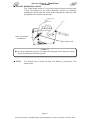
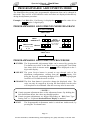
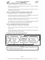
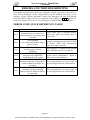
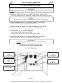
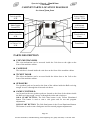
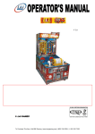
V 2.5 PLEASE NOTE: ► Read this manual BEFORE operating the machine. ► Keep this manual for your reference. ►Go to www.LAIGames.com click on Operator Access to register your games and receive of future updates. © LAI GAMES For More Information, Visit BMI Gaming | www.bmigaming.com | (800) 746-2255 | +1.561.391.7200 Operator's Manual – Slam'N'Jam © LAI GAMES TABLE OF CONTENTS SAFETY PRECAUTIONS ......................................................................................................1 MACHINE INSTALLATION AND INSPECTION ............................................................2 INTRODUCTION ....................................................................................................................3 SPECIFICATIONS ..............................................................................................................4 SLAM „N‟ JAM ASSEMBLY QUICK GUIDE ......................................................................5 DO’S AND DON’TS FOR ASSEMBLING SLAM„N‟JAM ............................................................5 TIPS FOR ASSEMBLING SLAM„N‟JAM.................................................................................5 TOOLS REQUIRED FOR ASSEMBLY ......................................................................................6 IDENTIFYING THE SLAM'N'JAM PARTS ................................................................................7 SLAM'N'JAM STEP BY STEP ASSEMBLY ....................................................................8 STEP ONE: ATTACHING FRONT SIDE FRAMES. .................................................................8 STEP TWO: ATTACHING REAR SIDE FRAMES. ..................................................................9 STEP THREE: ATTACHING THE FRONT PLAYFIELD. .........................................................9 STEP FOUR: ATTACH FRAME BRACES. ...........................................................................10 STEP FIVE: ATTACHING THE REAR PLAY FIELD .............................................................11 STEP SIX: ATTACHING BACKBOARD. ..............................................................................12 STEP SIX: ATTACHING BACKBOARD. ..............................................................................12 STEP SEVEN : ATTACHING TOP PANEL ..........................................................................13 STEP EIGHT: ATTACHING BALL HOOP TO BACKBOARD. ...............................................14 STEP EIGHT: ATTACHING BALL HOOP TO BACKBOARD. ...............................................14 STEP NINE: FITTING BALL SENSOR.................................................................................14 STEP TEN: FITTING SENSOR COVER. ...............................................................................15 STEP ELEVEN: FITTING THE 1ST BARRIER AND 2ND BARRIER. .........................................15 STEP TWELVE: REAR CABLING & NOISE DAMPENER BRACKET. ..................................16 STEP THIRTEEN: ATTACHING BALL GATE ASSEMBLY. ................................................17 STEP FOURTEEN : ATTACHING CABLE ..........................................................................18 HOW TO PUT BACK BOARD SUPPORTING BRACKET .........................................................19 COMPLETE ASSEMBLED MACHINE..........................................................................20 HOW TO PLAY ..................................................................................................................21 OPERATION ..........................................................................................................................22 OPERATIONAL DIAGRAM ...........................................................................................22 ATTRACT MODE ............................................................................................................22 PLAY MODE ....................................................................................................................22 TEST MODE .......................................................................................................................23 TEST MODE DIAGRAM .................................................................................................23 SOUND, LAMPS & DISPLAY TEST ..............................................................................24 SWITCH TEST .................................................................................................................24 RUN TEST ........................................................................................................................26 PROGRAMMABLE ADJUSTMENTS MODE ...............................................................27 i For More Information, Visit BMI Gaming | www.bmigaming.com | (800) 746-2255 | +1.561.391.7200 Operator's Manual – Slam'N'Jam © LAI GAMES PROGRAMMABLE ADJUSTMENTS MODE DIAGRAM............................................27 PROGRAMMABLE ADJUSTMENTS PROCEDURE ...................................................27 PROGRAMMABLE ADJUSTMENTS QUICK REFERENCE TABLE (V2.5) ..............28 PROGRAMMABLE ADJUSTMENTS DETAILED .......................................................29 AUDITS MODE ..................................................................................................................35 AUDITS MODE DIAGRAM ............................................................................................35 AUDIT PROCEDURE ......................................................................................................36 AUDITS QUICK REFERENCE TABLE .........................................................................36 AUDITS DETAILED ........................................................................................................37 LINKING GAMES .............................................................................................................38 INTRODUCTION .............................................................................................................38 HOW TO PLAY A LINK GAME .....................................................................................38 LINKING THE MACHINES ............................................................................................39 LINK CABLING ...............................................................................................................40 GAME POWER UP SEQUENCE .....................................................................................42 TROUBLESHOOTING THE LINK SYSTEM.................................................................43 ERRORS AND TROUBLESHOOTING ..........................................................................45 ERROR CODE QUICK REFERENCE TABLE ...............................................................45 TROUBLESHOOTING GAME ERRORS .......................................................................46 FUSE INFORMATION ......................................................................................................47 FUSE LOCATION DIAGRAM ........................................................................................47 SECTION A: SERVICE INSTRUCTIONS ........................................................................48 LOCATING AND ACCESSING PARTS .........................................................................49 PARTS LOCATION DIAGRAM .....................................................................................49 CABINET PARTS LOCATION DIAGRAM ...................................................................50 PARTS DESCRIPTION ....................................................................................................50 LAMPS ................................................................................................................................52 MAINTENANCE ................................................................................................................53 SECTION B: TECHNICAL DETAILS ...............................................................................54 MAINS VOLTAGE ADJUSTMENT ................................................................................55 TICKET DISPENSER REFERENCE GUIDE ................................................................56 3D EXPLODE PARTS........................................................................................................61 SLAM'N'JAM MAIN WIRING DIAGRAM.......................................................................67 ii For More Information, Visit BMI Gaming | www.bmigaming.com | (800) 746-2255 | +1.561.391.7200 Operator's Manual – Slam'N'Jam © LAI GAMES SAFETY PRECAUTIONS The following safety precautions and advisories are used throughout this manual and are defined as follows. * WARNING! * Disregarding this text could result in serious injury. * CAUTION! * Disregarding this text could result in damage to the machine. * NOTE! * An advisory text to hint or help understanding. BE SURE TO READ THE FOLLOWING * WARNING! * Always turn OFF Mains AC power and unplugged the game, before opening or replacing any parts. Always when unplugging the game from an electrical outlet, grasp the plug, not the line cord. Always connect the Game Cabinet to grounded electrical outlet with a securely connected ground line. Do Not install the Game Cabinet outdoors or in areas of high humidity, direct water contact, dust, high heat or extreme cold. Do Not install the Game Cabinet in areas that would present an obstacle in case of an emergency, i.e. near fire equipment or emergency exits. * CAUTION! * Always use a Digital Multimeter, logic tester or oscilloscope for testing integrated circuit (IC) logic PC boards. The use of a continuity tester is not permitted. Do Not Connect or disconnect any of the integrated circuit (IC) logic PC boards while the power is ON. Do Not use any fuse that does not meet the specified rating. Do Not Subject the game cabinet to extreme temperature variations. Reliability of electrical components deteriorates rapidly over 60 oC. Page 1 For More Information, Visit BMI Gaming | www.bmigaming.com | (800) 746-2255 | +1.561.391.7200 Operator's Manual – Slam'N'Jam © LAI GAMES MACHINE INSTALLATION and INSPECTION When installing and inspecting “Slam'N'Jam”, be very careful of the following points and pay attention to ensure that the players can enjoy the game safely. Slam‟N‟Jam is shipped from the factory in “Flat Pack” form and requires assembling. Be sure to turn the power OFF before working on the machine. * WARNING! * Always Turn OFF mains power before removing safety covers and refit all safety covers when work is completed. Make sure the power cord is not exposed on the surface (floor, ground, etc.) where people walk through. Check that the rubber glide feet levelers are set evenly on the floor so that the game cabinet is unable to roll and is stable. Always make complete connections for the integrated circuit (IC) logic PC Boards and other connectors. Insufficient insertion can damage the electrical components. * CAUTION! * Before switching the machine on be sure to check that it has been set on the correct voltage for your area! Refer to the mains voltage adjustment section of this manual on. Machines are normally shipped on 220V AC unless otherwise specified. Only qualified personnel should inspect or test the integrated circuit (IC) logic PC Boards. If any integrated circuit (IC) logic PC Boards should need servicing. Please contact the nearest LAI GAMES distributor. (Refer to the back page of this manual) Page 2 For More Information, Visit BMI Gaming | www.bmigaming.com | (800) 746-2255 | +1.561.391.7200 Operator's Manual – Slam'N'Jam © LAI GAMES INTRODUCTION CONGRATULATIONS! You have just bought the “Slam'N'Jam”, another great product from LAI GAMES. This is, in our opinion, one of the best basketball games made in the world. It is very simple yet challenging to play and includes features not previously available in any other basketball, like “Match Play” and “Double Ticket Time”. Also added, is the ability to link from 2, up to 8 machines for exciting head-tohead competition plus you are able to link an optional Overhead Bonus Display. We hope you take the time to read this manual and learn about the many other features and user-friendly adjustments that can be made to “fine-tune” the game for maximum earning potential. DESCRIPTION The “Slam'N'Jam” is a single player basketball game with linking capabilities. Players use their skill and accuracy to throw as many balls through the basketball hoop as they can during the game, to win tickets. PACKAGING At delivery, the machine should arrive in good condition. To move the packaged machine for transport or placement, use a forklift and take care not to hit the package or stack heavy objects on top, as this may cause damage to the machine. * NOTE! * Slam‟N‟Jam is shipped from the factory in “Flat Pack” form and requires assembling. CONTENTS The “Slam'N'Jam” cabinet & Frame Flat Packs (Requires Assembly) 4 x Size 5 Basketballs Keys: 2 x coin door keys 2 x ticket door key “Slam'N'Jam” Operator‟s Manual Slam'N'Jam Assembly Manual IEC Power Cord (In cash box) Parts & Accessories (In cash box & cabinet) Page 3 For More Information, Visit BMI Gaming | www.bmigaming.com | (800) 746-2255 | +1.561.391.7200 Operator's Manual – Slam'N'Jam © LAI GAMES SPECIFICATIONS DIMENSIONS Weight: Height: Width: Length: Power: 280 kg 2631mm 900mm 2310mm Maximum Average (617lb) (104”) (35”) (91”) 380 W – (220V @ 1.7A) (120V @ 3.2A) 330 W – (220V @ 1.5A) (120V @ 2.8A) ELECTRIC SUPPLY The game has the option to operate on a 110V, 120V, 220V or 240V AC 50/60Hz single phase mains electric supply. The supply must be a three wire grounded supply. * CAUTION! * Before switching the machine on be sure to check that it has been set on the correct voltage for your area! Please Refer to the mains voltage adjustment section of this manual. Machines are normally shipped on 220V AC unless otherwise specified. LOCATION REQUIREMENTS Ambient temperature: Ambient humidity: Ambient U.V. radiation: Vibrations level: between 5°C and 40°C. Low Very low Low Page 4 For More Information, Visit BMI Gaming | www.bmigaming.com | (800) 746-2255 | +1.561.391.7200 Operator's Manual – Slam'N'Jam © LAI GAMES SLAM „N‟ JAM ASSEMBLY Quick Guide Do‟s and Don‟ts for Assembling Slam„N‟Jam Do read the Slam„N‟Jam assembly manual as it will help you in the correct step by step order of assembly Do take note of what size bolts are used where when assembling Slam„N‟Jam Do make sure that all cables are free to move and not pinched or jammed under the playfield or other parts when assembling Slam„N‟Jam. Do make sure that all earth point cables are connected when assembling both the Front Frames and Front Playfield Speaker Pods on Slam„N‟Jam. Don‟t forget to remove the Slam„N‟Jam keys from inside the game cabinet before bolting the front playfield in place. Don‟t forget after assembling Slam„N‟Jam to check and tighten all the bolts. Don‟t forget to check the voltage setting of Slam„N‟Jam is set to the mains voltage for your country before applying power. TIPS for Assembling Slam„N‟Jam We recommend using two people when assembling Slam„N‟Jam. While one person is able to do most of the assembly, using two people will be much easier. A stepladder will also be very handy during assembly. We Recommend that assembling Slam„N‟Jam is best done on a level and even surface. Adjust the rubber feet on the frames to align them for easier assembly. We recommend when assembling Slam„N‟Jam not tightening all the bolts until all major parts are fitted. This will allow the easy alignment of holes as the frame is not held rigid. * NOTE! * Slam„N‟Jam uses metric size Nuts & Bolts throughout its construction . To help in ease of moving Slam„N‟Jam the machine can be split into two separate halves. Remove the eight Bolts holding the Front and Rear Frame Halves together and unplug the main backboard and lighting cables at the connectors near the Ball Gate. The Ball Gate stays fixed to the front half of the machine. Page 5 For More Information, Visit BMI Gaming | www.bmigaming.com | (800) 746-2255 | +1.561.391.7200 Operator's Manual – Slam'N'Jam © LAI GAMES Tools Required For Assembly 1 x 4 mm Allen Key 1 x 150 mm Adjustable Spanner 1 x 13 mm Ring and Open end Spanner 1 x 10 mm Ring and Open end Spanner 1 x 8 mm Ring and Open end Spanner One person is able to do most of the assembly, but using two people will be much easier. A stepladder will also be very handy during assembly. Unpack the machine and be sure to check that all parts are present. As a quick reference, refer to the photos on Page 7. * NOTE! * Be sure to remove the keys from the game cabinet and install into locks before assembly. * NOTE! * This job is easiest to complete using two people. One to hold the frame, and one to bolt the frame in place. Page 6 For More Information, Visit BMI Gaming | www.bmigaming.com | (800) 746-2255 | +1.561.391.7200 Operator's Manual – Slam'N'Jam © LAI GAMES Identifying the Slam'N'Jam Parts The photograph below displays the parts and their names for you to refer to while assembling the “Slam „n‟ Jam”. This will assist you in locating the parts more easily GAME CABINET FRONT RIGHT FRAME FRONT LEFT FRAME REAR RIGHT FRAME REAR LEFT FRAME FRONT PLAYFIELD REAR PLAYFIELD BALL GATE ASSEMBLY BRACES BRACKET BACK BOARD PANEL TOP PANEL 1ST BARRIER 2ND BARRIER HARDWARE PACK HOOP Page 7 For More Information, Visit BMI Gaming | www.bmigaming.com | (800) 746-2255 | +1.561.391.7200 Operator's Manual – Slam'N'Jam © LAI GAMES SLAM'N'JAM STEP BY STEP ASSEMBLY M6 x 50 mm Allen head bolts Rubber Feet (Frame Glides) STEP ONE: Attaching Front Side Frames. Attach to the back of the two front frames, two of the *Rubber Feet (Frame Glides) supplied Firmly bolt the two front side frames onto the game cabinet using the *four M6 x 50mm Allan head bolts, eight washers and four M6 locknuts supplied. Page 8 For More Information, Visit BMI Gaming | www.bmigaming.com | (800) 746-2255 | +1.561.391.7200 Operator's Manual – Slam'N'Jam © LAI GAMES STEP TWO: Attaching Rear Side Frames. * NOTE! * This job is easiest to complete using two people. One to hold the frame, and one to bolt the frame in place. Attach to the two rear frames four of the *Rubber Feet (Frame Glides) supplied Bolt the two rear side frames to the front frames using the *eight M8 x 30mm bolts, washers, spring washers and nuts supplied. * HINTS! * Adjust the rubber feet on the frames to align them for easier assembly. To help in alignment of panels don‟t tighten bolts until most of the assembly is completed. Don‟t place the bolts in the third hole from the bottom; this is for the barrier mesh. STEP THREE: Attaching the Front Playfield. * NOTE! * DON‟T FORGET to remove the keys from inside the game cabinet. Fit the front playfield to the front side frames, and bolt in place using the *six M6 x 50mm Knockdown bolts, washers, Nylon lock nuts supplied, access to four of the bolts is through the front door. Also plug in the 6 PIN, left and right speaker cables into the game cabinet, and remember to attach the earth connector to each of the speaker Pods. Page 9 For More Information, Visit BMI Gaming | www.bmigaming.com | (800) 746-2255 | +1.561.391.7200 Operator's Manual – Slam'N'Jam © LAI GAMES STEP FOUR: Attach Frame Braces. MIDDLE BRACE REAR BRACE Attach the Middle and Rear Frame Braces on top of the rubber leveling feet using the four, M12 nuts and spring washers supplied. (Refer to picture below for detail) * NOTE! * Be sure to check AND TIGHTEN ALL ASSEMBLY BOLTS! Page 10 For More Information, Visit BMI Gaming | www.bmigaming.com | (800) 746-2255 | +1.561.391.7200 Operator's Manual – Slam'N'Jam © LAI GAMES STEP FIVE: Attaching the Rear Play Field Fit the rear playfield to the rear side frames, and bolt in place using the *six M6 x 50mm Knockdown bolts, washers and Nylon lock nuts supplied. * Hardware found in Playfield Pack from Cashbox Page 11 For More Information, Visit BMI Gaming | www.bmigaming.com | (800) 746-2255 | +1.561.391.7200 Operator's Manual – Slam'N'Jam © LAI GAMES STEP SIX: Attaching Backboard. * NOTE! * It is faster with two people for this part of the assembly. Fit the backboard and bolt in place using the *Ten M6 x 50mm Knockdown bolts, washers, Nylock nuts supplied, * Hardware found in Backboard Pack from Cashbox STEP SEVEN: Attaching Top Panel Page 12 For More Information, Visit BMI Gaming | www.bmigaming.com | (800) 746-2255 | +1.561.391.7200 Operator's Manual – Slam'N'Jam © LAI GAMES STEP SEVEN : Attaching Top Panel Attach the top panel to the two rear side panels using the *eight M6 x 50mm, washers and Nylock nuts supplied. Page 13 For More Information, Visit BMI Gaming | www.bmigaming.com | (800) 746-2255 | +1.561.391.7200 Operator's Manual – Slam'N'Jam © LAI GAMES STEP EIGHT: Attaching Ball Hoop to Backboard. Firmly attach the ball hoop to the backboard using the *four M8 x 45mm bolts and washers supplied. STEP NINE: Fitting Ball Sensor. Fit the electronic sensor through the hole in the backboard and plug in to the 4 PIN Plug. Page 14 For More Information, Visit BMI Gaming | www.bmigaming.com | (800) 746-2255 | +1.561.391.7200 Operator's Manual – Slam'N'Jam © LAI GAMES STEP TEN: Fitting Sensor Cover. Fit the sensor cover onto the four bolts from the ball hoop using the *four sets of M8 washers, spring washers and nuts supplied. STEP ELEVEN: Fitting the 1st barrier and 2nd barrier. Attach the barrier panel assembly at the top bolt holes using the *two, M8 x 30mm bolts, flat washers, spring washers and nuts supplied. Next attach at the bottom bolt holes together with the ball stop bar using the *two, M8 x 30mm bolts, flat washers, spring washers and nuts supplied. Page 15 For More Information, Visit BMI Gaming | www.bmigaming.com | (800) 746-2255 | +1.561.391.7200 Operator's Manual – Slam'N'Jam © LAI GAMES STEP TWELVE: Rear Cabling & Noise Dampener Bracket. Insert the Top Spotlight Panel cable into the conduit on the rear of the backboard and clip the conduit cover firmly in place. Attach the adjustable noise dampener bracket to the backboard with the *two, 8mm x 20mm bolts and flat washers provided and adjust so playfield is tight up against the bottom of the Backboard Panel. * Bracket & Hardware found in Backboard Pack from Cashbox Page 16 For More Information, Visit BMI Gaming | www.bmigaming.com | (800) 746-2255 | +1.561.391.7200 Operator's Manual – Slam'N'Jam © LAI GAMES STEP THIRTEEN: Attaching Ball Gate Assembly. Attach the ball gate to the frame from rear of the machine using four bolts M8 x 30 mm, washer spring washer and nuts supplied * HINTS* You may need to pull the frames together to align the holes on the frame to the ball gate assembly To help in alignment of panels don‟t tighten bolts until most of the assembly is completed Page 17 For More Information, Visit BMI Gaming | www.bmigaming.com | (800) 746-2255 | +1.561.391.7200 Operator's Manual – Slam'N'Jam © LAI GAMES STEP FOURTEEN : Attaching Cable Connect all the connector according to the size of each connectors, pull off the cable rail cover on each side of the back front playfield and on the back of rear playfield also on the back panel. Put all the cable into the cable rail close the cable rail cover make sure all the cable in secure position inside the cable rail. Assembly now Completed Page 18 For More Information, Visit BMI Gaming | www.bmigaming.com | (800) 746-2255 | +1.561.391.7200 Operator's Manual – Slam'N'Jam © LAI GAMES How to put Back Board Supporting Bracket To make an easy secure transportation and also easy installation we put the supporting bracket as per following photos; When you receive the machine you should reposition the supporting bracket as following photo ; Unscrew the bracket reposition accordingly Complete bracket position. Page 19 For More Information, Visit BMI Gaming | www.bmigaming.com | (800) 746-2255 | +1.561.391.7200 Operator's Manual – Slam'N'Jam © LAI GAMES COMPLETE ASSEMBLED MACHINE. * CAUTION! * BE SURE TO CHECK MAINS VOLTAGE AND TEST BEFORE USAGE! Page 20 For More Information, Visit BMI Gaming | www.bmigaming.com | (800) 746-2255 | +1.561.391.7200 Operator's Manual – Slam'N'Jam © LAI GAMES HOW TO PLAY PLAYERS ATTEMPT TO THROW BALLS THROUGH THE HOOP TO SCORE POINTS. THE MORE POINTS SCORED THE MORE TICKET WON. Insert coin/s for credits. Players can choose to start a linked game or solo game by pressing the flashing “LINK” or “SOLO” game button respectively. Where there is only a single game available, only the “SOLO” button will be flashing. Pressing the “LINK” or “SOLO” game buttons while the “Double Tickets” lamp is flashing will start a game in which that machine will pay twice as many tickets for points scored. If the “LINK” button selected the button light will stay on and the game will say “Waiting for more players”. A 10 second count down will allow time for extra players to join in the competition. If the “SOLO” button selected the button light will stay on, the game will start immediately and gate will release balls to the player. Throwing balls through the hoop will score 2 points. When the 3 point lamps are flashing, Balls through the hoop will score 3 points. At the end of the game play the gate will close and retain the balls. Tickets are awarded based on the number of points scored; Extra tickets or credits can be won for, Beating the High Score, Scoring the most points in a linked competition game, or Winning the Match Number at the end of play. Page 21 For More Information, Visit BMI Gaming | www.bmigaming.com | (800) 746-2255 | +1.561.391.7200 Operator's Manual – Slam'N'Jam © LAI GAMES OPERATION The “Slam'N'Jam” game has five operational modes: Attract mode, Play mode, Test mode, Programmable Adjustments Mode and Audits Mode. OPERATIONAL DIAGRAM POWER UP ATTRACT MODE PRESS TEST TEST MODE PLAY MODE * NOTE! * Entering test mode will clear any stored credits PRESS TEST PROGRAMMABLE ADJUSTMENTS MODE PRESS TEST AUDITS MODE PRESS TEST ATTRACT MODE The Attract mode provides a light and sound display, while the game is not being played. This feature is to attract potential customers to play the game. The attract mode sound can be turned on and off PLAY MODE The Slam'N'Jam has two play modes. The Standard Coin Play mode, where a coin, or coins are inserted. Or Free Play where no coins are necessary. COIN PLAY The Coin Play mode is entered from Attract mode, by inserting coins in any of the two coin slots on the front of the machine cabinet, then following the instructions in the “How to Play” section of this manual. FREE PLAY The free play mode is entered from attract mode by holding the Service button for longer than five second F r E will be displayed on the 3-digit LED display. To get back to normal game Play mode Switch Off and On the Machine. Page 22 For More Information, Visit BMI Gaming | www.bmigaming.com | (800) 746-2255 | +1.561.391.7200 Operator's Manual – Slam'N'Jam © LAI GAMES TEST MODE The Slam'N'Jam Test mode has Three Test Configurations allowing you to explore the functioning of the Sound, Light & Display, the Game Switches and to allow an operational test of the Ball Gate. (Refer to the Test Mode Diagram below). The Test mode is also used for Clearing Game Errors. If there is an active error, its code will be displayed. To try to clear the error code, press the red test button once. The error can be bypass by quickly pressing the red test button twice. * NOTE! * Entering Test Mode will CLEAR any CREDITS remaining in the game. If during test mode no ADJUSTMENTS or actions are made to the game for approximately four minutes, it will automatically RETURN to Attract Mode. TEST MODE DIAGRAM ATTRACT MODE PLAY MODE PRESS TEST SOUND, LAMPS & DISPLAY TEST The Display counts, all Lamps are flashing and Sound is played 0 0 0 1 1 1 9 9 9 PRESS TEST SWITCH INPUT TEST No INPUT is active C Service switch is active C 0 1 Coin switch is active C 0 0 0 Gate Open Switch is active To 2 C 0 Ball Sensor is active 6 C 0 8 PRESS TEST RUN TEST r r r R PRESS SERVICE Ball Gate Opening r 1 Ball Gate Open BALL GATE RUN TEST r 3 Press Service button to activate Gate Opening Error LED displays run test function E r 6 Er# indicates Ball Gate problem Ball Gate Closing PRESS SERVICE r 0 Ball Gate Closed Loops back r 2 Gate Closing Error E r 5 PRESS TEST PROGRAMMABLE ADJUSTMENTS MODE Page 23 For More Information, Visit BMI Gaming | www.bmigaming.com | (800) 746-2255 | +1.561.391.7200 Operator's Manual – Slam'N'Jam © LAI GAMES SOUND, LAMPS & DISPLAY TEST ENTER The Sound, Lamp & Display test is entered from Attract mode by pressing the test button once. * NOTE! * If there is an active error displayed, press the red test button once to try and clear the error. If the error code will not clear, it can be bypass by quickly pressing the red test button twice. DURING THE TEST: o Game music and a voice over will be played. o The Solo and Link Start button lamps will flash on and off o The 3-Point and Match lights will run a test pattern sequence. o The 3-digit display will count from 000 to 999 and then repeat. EXIT The Sound, Lamp & Display test is exited by pressing the test button. The next test will be switch test. SWITCH TEST ENTER The Switch Test can be entered by pressing the Test button once while in the Sound, Light & display test or by pressing the Test button twice while in Attract mode, C X X will be displayed on the 3-digit display where „XX‟ is a number representing the switch that is active. TESTING THE GAME SWITCHES All game switches have a code from C1 to C8 as tabled below. By activating any of the switches, their code will be displayed on the 3digit display. If no switches are active then C 0 0 will be displayed. CODE C0 C1 C2 C3 C4 C5 C6 C7 C8 DISPLAY C 0 0 C 0 1 C 0 2 C 0 3 C 0 4 C 0 5 C 0 6 C 0 7 C 0 8 SWITCH FUNCTION No Switch Active Service Switch Active Coin Switch Active Ticket Notch Solo Start Button Active Link Start Button Active Gate Closed Switch Active Gate Open Switch Active Ball Sensor Active Normal condition for the game is switches are active. C 0 3 & C 0 6 SWITCH LOCATION Service Panel Coin Door Ticket Door Left Speaker Pod Right Speaker Pod Ball Gate Mechanism Ball Gate Mechanism Cabinet Back Panel , Ticket Notch and Ball Gate * NOTE! * Several switches can be simultaneously activated in Switch test. The display will then consecutively show their codes, indicating which switches are active. However, it is much easier to test the game switches individually.. Page 24 For More Information, Visit BMI Gaming | www.bmigaming.com | (800) 746-2255 | +1.561.391.7200 Operator's Manual – Slam'N'Jam © LAI GAMES TICKET DISPENSER NOTCH The Ticket Notch Switch (C1) can be activated or deactivated from the Ticket Feed Button on the Ticket Dispenser PCB or by manually pushing the tickets from the ticket holder through the dispenser after pulling the ticket release rod upwards Ticket Tensioning mechanism Ticket release rod * NOTE! * For more information on the servicing and testing the ticket dispenser please look at the Dispenser Reference guide. EXIT The Switch Test is exited into Run Test Mode by pressing the Test Button once. Page 25 For More Information, Visit BMI Gaming | www.bmigaming.com | (800) 746-2255 | +1.561.391.7200 Operator's Manual – Slam'N'Jam © LAI GAMES RUN TEST ENTER The Run Test can be entered by pressing the Test button once while in the Switch Test or by pressing the Test button three times while in Attract mode, r r r will be displayed on the 3-digit display. SELECT Operation of the Ball Gate Motor and Switch can be tested. To start the test, press the Service button. The Service button is then pressed again to alternately open and close the gate. Refer to the following table for the status of the Ball Gate Run Test: CODE DISPLAY SWITCH FUNCTION r 0 R-0 Ball Gate is Closing r 1 R-1 Ball Gate is Opening R-2 Ball Gate is Closed r 2 R-3 Ball Gate is Open r 3 E r 5 Er5 Ball Gate Closing Error E r 6 Er6 Ball Gate Opening Error EXIT The Run Test is exited into Programmable Adjustments Mode by pressing the Test Button once. Page 26 For More Information, Visit BMI Gaming | www.bmigaming.com | (800) 746-2255 | +1.561.391.7200 Operator's Manual – Slam'N'Jam © LAI GAMES PROGRAMMABLE ADJUSTMENTS MODE The Slam'N'Jam has twenty nine programmable adjustments that can be changed in this mode. They are P01 to P29 and their codes and values are displayed alternatively during the adjustment procedure. Example: Code P01 (Solo / Link Setting) is displayed as 2 on the 3-digit display. P 0 1 and its value of 1 as PROGRAMMABLE ADJUSTMENTS MODE DIAGRAM RUN TEST MODE PRESS TEST PROGRAMMABLE ADJUSTMENTS MODE P P P PRESS SERVICE PRESS START to change value 0, 1, 2 P 0 1 PRESS SERVICE P 2 9 To step from P01 to P29 2 0 0 REPEATEDLY 0 2 Loops back to P01 PRESS TEST AUDIT MODE PROGRAMMABLE ADJUSTMENTS PROCEDURE ENTER The Programmable Adjustments Mode can be entered by pressing the Test button once while in the Run Test or by pressing the Test button four times while in Attract mode, P P P will be displayed on the 3digit credit display. SELECT The green Service button is pressed to step through each of the adjustment configurations, starting from the P 0 1 display, P01 being the first step, continuing through to P29, and then looping again from P01 to P29 until the mode is exited. CHANGE The Solo Start button is pressed to change the displayed value. The value can only be stepped up by using the Start button, but the value will loop back to its minimum value the next step after its max value. * NOTE! * Certain program adjustments have a fast adjustment feature. By holding the Solo Start button down, the values step through quicker. Certain program adjustments are skipped depending on P01 Game Type Setting and / or if optional Overhead Bonus Display is attached EXIT The Programmable Adjustments mode is exited into Audits mode, by pressing the Test button once. Page 27 For More Information, Visit BMI Gaming | www.bmigaming.com | (800) 746-2255 | +1.561.391.7200 Operator's Manual – Slam'N'Jam © LAI GAMES PROGRAMMABLE ADJUSTMENTS QUICK REFERENCE TABLE (V2.5) CODE P01 P02 P03 P04 P05 P06 P07 P08 P09 P10 P11 P12 P13 P14 P15 P16 to P27 PROGRAMMABLE ADJUSTMENTS 0 = Standard 1 = Master 2 = Slave 0 = No Bonus 1 = Credits 2 = Tickets 1 – 10 credits (P02) 1 – 100 tickets (P02) 1 – 10 1 – 10 0 – 100 45 – 90secs in 5 sec steps ON [ 1 ] or OFF [ 0 ] ON [ 1 ] or OFF [ 0 ] 0 – 10 0 = During Game 1 = End of Game 2 = After Match Feature* ON [ 1 ] or OFF [ 0 ] 15 – 120mins in 15min steps 15 – 120mins in 15min steps 1 – 5mins in 1 min steps OPTIONAL VALUES DEFAULT SETTINGS FEATURES 0, 1, 2 2 Game Type Setting Solo / Linking 0, 1, 2 2 Link Winner Bonus Type 1, 2, 3...10 Cr 1, 2, 3..100 Tic 1, 2, 3…10 1, 2, 3…10 1, 2, 3…100 5 Link Winner Bonus Amount 01 01 06 Game Pricing No. Coins Game Pricing No. Credits Ticket Payout Points / Ticket 45, 50…90 45 Game Time Adjustment 1 (on), 0 (off) ON Match Feature ON / OFF 1 (on), 0 (off) ON Attract Sound ON / OFF 0, 1, 2…10 0 Mercy Tickets 0, 1, 2 02 Ticket Payout Time *(Dependant on P08 setting) 1 (on), 0 (off) ON 15, 30, 45…120 15, 30, 45…120 1, 2, 3…5 30 30 3 Double Ticket Feature ON / OFF Double Tickets Wait Time Adjustment Double Tickets Random Start Time Adjustment Double Tickets Lamp On Time Only available through the optional Overhead Bonus Display Unit, when fitted. P28 0 = No Free Game for High Score 1 = Free Game on paid games 2 = Free Game on any games 0, 1, 2 0 Free Game for High Score Mode P29 10 – 200 in 5 point steps 10, 15, 20..200 200 High Score Level for Free Game P30 ON or OFF ON or OFF ON Ticket option * NOTE! * The default settings will give an average payout of 7 - 10 tickets per game. P28 & P29 are disabled when Optional Overhead Bonus Display is fitted Page 28 For More Information, Visit BMI Gaming | www.bmigaming.com | (800) 746-2255 | +1.561.391.7200 Operator's Manual – Slam'N'Jam © LAI GAMES PROGRAMMABLE ADJUSTMENTS DETAILED P01 = GAME TYPE SETTING (default 2) (Adjustable 0 – 2) This game adjustment allows the operator to set whether the game is a linked game or not. For detailed information regarding game linking, refer the Linking Games section of the manual. THERE ARE THREE SETTINGS: 0 – “STANDARD - NOT LINKED”. If this option is set, the game is a Single stand-alone game and will not communicate with other games. * NOTE! * If a game is set to standard game adjustment [ 0 ], P02 and P03 are skipped. 1 – “LINKED MACHINE - MASTER”. If this option is set, the game is the “Master Machine” in a linked bank of 2 – 8 machines. (For more details refer to the Linking Games section of the manual) * NOTE! * There can only be ONE “Master Machine” in a group of linked games. If the optional Overhead Bonus Display is fitted, it is ALWAYS SET TO MASTER and all games linked with it are set to slave. (For more Information, see the separate Overhead Bonus Display Manual) 2 – “LINKED MACHINE - SLAVE”. If this option is set, the game is a “Slave Machine” in a bank of 2 – 8 machines. (For more details refer to the Linking Games section of the manual) * NOTE! * If a game is set to Slave, there is no access to any of the other Programmable Games Adjustments (P02 – P15). Only the Master can access game adjustments in a linked bank of machines. Page 29 For More Information, Visit BMI Gaming | www.bmigaming.com | (800) 746-2255 | +1.561.391.7200 Operator's Manual – Slam'N'Jam © LAI GAMES P02 = LINK GAME WINNER BONUS TYPE (default 02) (Adjustable 0 – 2) This game adjustment allows the operator to set what type of bonus the winning player of a linked game receives. (For more details refer to the Linking Games section of the manual) * NOTE! * This program option is only accessible by the “Master Machine” in a Linked bank of machines. THERE ARE THREE SETTINGS: 0 – “NO BONUS”. If no bonus is selected, game program step P03 is skipped. 1 – “CREDITS”. The Linked Game winner will win free credits (free game). The number of credits won is adjustable in program game adjustment P03. 2 – “TICKETS”. The Linked Game winner will win extra tickets. The number of extra tickets won is adjustable in program game adjustment P03. * NOTE! * The bonus tickets are ADDITIONAL to normal tickets won during the game. They are also additional to jackpot tickets, if the optional Overhead Bonus Display is fitted. P03 = LINK GAME WINNER BONUS AMOUNT (default 5) (Adjustable 1 – 10 Credits, or 1 – 100 Tickets) This game adjustment allows the operator to set the number of bonus credits or tickets (depending on program game adjustment P02) that the winning player on a linked game receives. If P02 is set to tickets, this option is adjustable from 1 – 100 tickets. If P02 is set to credits, this option is adjustable from 1 – 10 credits. * NOTE! * This program option is only accessible by the “Master Machine” in a Linked bank of machines. P04 = NUMBER OF COINS PER CREDIT (default 01) (Adjustable 1 – 10) This variable sets the number of coins that need to be inserted in exchange for each game credit. It can be set to either of 1, 2, 3… to 10 coins for one credit. P05 = NUMBER OF PLAYS PER CREDIT (default 01) (Adjustable 1 – 10) This sets the number of games for each credit. It can be set to either of 1, 2, 3… to 10 plays for one credit. Page 30 For More Information, Visit BMI Gaming | www.bmigaming.com | (800) 746-2255 | +1.561.391.7200 Operator's Manual – Slam'N'Jam © LAI GAMES P06 = NUMBER OF POINTS PER TICKETS (default 06) (Adjustable 0 – 100) This is the number of points the player needs to score to win one ticket. * NOTE! * Setting the Number Of Points Per Tickets P06 to 0 will result in no tickets paid for any score. This is useful for promotion play or to disable ticket payout. To totally disable ticket payout, Linked Game winner Bonus Type P02 will need to be set to 0 or 1 and also Mercy Tickets P10 will need to be set 0 P07 = GAME TIME (default 45 Seconds) (Adjustable 45 – 90 seconds, in 5 - second steps) This sets the length of time that each game plays for in seconds. The time does not include the starting intro and end of game feature. It is only “Game Play” time. * NOTE! * The last 10 seconds of game play is “3 Point Score” (3 points for each score instead of 2 points). This is regardless of the game time setting. P08 = MATCH FEATURE (default 01) (Adjustable ON [ 1 ] or OFF [ 0 ] ) This adjustment turns the match feature ON [ 1 ] or OFF [ 0 ]. The match feature, when set to ON [ 1 ], plays at the end of the game and is similar to pinball. When the game ends, the last digit of the player‟s score remains on the three-digit display. The third digit of the three-digit display will then randomly tumble numbers until it stops. If the numbers match, the player wins a free game. During the match feature the “Match” lamp above the three digit display flashes. * NOTE! * Match wins are random, but on average are approximately 1 in 10 games. P09 = ATTRACT MODE SOUND (default 01) (Adjustable ON [ 1 ] or OFF [ 0 ] ) This adjustment turns the attract mode sound ON [ 1 ] or OFF [ 0 ]. This is the sound and music that the game generates to attract customers when it is not being played. The music cycles approximately every 4 minutes. Page 31 For More Information, Visit BMI Gaming | www.bmigaming.com | (800) 746-2255 | +1.561.391.7200 Operator's Manual – Slam'N'Jam P10 = MERCY TICKET © LAI GAMES (default 0) (Adjustable 0 – 10) This adjustment turns the Mercy Ticket feature ON [ 1 – 10 ] or OFF [ 0 ]. If it is set ON, it allows you to adjust the number of Mercy Tickets given. Mercy Tickets are tickets awarded to players that don‟t have enough skill to score sufficient points to win a ticket during their game. This feature is good for rewarding very young children who may not be able to throw the ball well enough to win tickets. To turn the feature OFF, set it to [ 0 ]. Setting it from 1 – 10 sets the number of tickets paid out at the end of the game. * NOTE! * Mercy Tickets are only paid if NO other tickets are won during the game. They are NOT additional tickets. P11 = THE TIME TICKETS ARE PAID OUT (default 02) (Adjustable 0 – 2) This allows the operator to adjust when the tickets that were won during the game are paid out to the player. THERE ARE THREE SETTINGS: 0 – The tickets are paid out during the game as they are won. 1 – The tickets are paid out at the end of the game. 2 – The tickets are paid out after the match feature. (If active, refer to P08) P12 = DOUBLE TICKET FEATURE (default [ 01 ] ) (Adjustable ON [ 1 ] or OFF [ 0 ]) This option turns the Double Ticket feature ON [ 1 ] or OFF [ 0 ]. This feature is designed to encourage people to play the game when it has not been used for some time. If the game has been unattended for a certain length of time, (Operator Adjustment P13) the “Double Ticket” lamp on the front of the machine will randomly flash. If a customer inserts a coin during this period, the tickets that they would normally win on their game will be doubled. * NOTE! * Only GAME tickets are doubled, NOT Link Winners Bonus Tickets OR Bonus Tickets if an Overhead Bonus Display is fitted. If the Double Tickets feature is turned OFF [ 0 ], the program steps P13 – P15 will be skipped Page 32 For More Information, Visit BMI Gaming | www.bmigaming.com | (800) 746-2255 | +1.561.391.7200 Operator's Manual – Slam'N'Jam © LAI GAMES P13 = DOUBLE TICKETS WAIT TIME (default 30) (Adjustable 15 – 120 minutes, in 15 - minute steps) This allows the operator to adjust the time that the game waits before the Double Ticket feature becomes active. This time period starts from the end of the last game and is canceled if a game is started before the timer elapses. P14 = DOUBLE TICKETS RANDOM START TIME (Default 30) (Adjustable 15 – 120 minutes, in 15 - minute steps) This allows the operator to adjust the time period, AFTER the wait time (Refer P13) that the “Double Tickets” lamp will become active. This time period starts from the end of Double Tickets Wait Time and is canceled if a game is started before the Double Ticket Lamp is lit. The “Double Tickets” lamp will become active only ONCE, randomly during this period. This random start prevents people from timing the feature. P15 = DOUBLE TICKETS LAMP ON TIME (default 3) (Adjustable 1– 5 minutes, in 1 - minute steps) This is the time period that the “Double Tickets” lamp will flash for when it becomes active. Starting a game while the Double Tickets Lamp is flashing will pay double the value of tickets for any game points played. DOUBLE TICKET FEATURE DIAGRAM FROM END OF LAST GAME S T A R T P13 (Default 30 min) Double Tickets WAIT TIME PERIOD Canceled if game is started P14 (Default 30 min) Double Tickets RANDOM START TIME PERIOD (Can light at any time) Canceled if game is started P15 (Default 3 min) Double Tickets LAMP ON TIME PERIOD Double Tickets paid if game is started * NOTE! * The Double Tickets feature only becomes ACTIVE if NO-ONE has played the game before the wait time expires. Page 33 For More Information, Visit BMI Gaming | www.bmigaming.com | (800) 746-2255 | +1.561.391.7200 Operator's Manual – Slam'N'Jam © LAI GAMES P16 to P27 OVERHEAD BONUS DISPLAY SETTINGS (Only Available from Overhead Bonus Display) These Programmable Adjustment Settings are not available unless the Optional Overhead Bonus Display is fitted. See your Overhead Bonus Display Manual for details. HIGH SCORE PROGRAMMABLE ADJUSTMENT SETTINGS * NOTE! * The High Score Programmable Adjustment Settings are not available if the Optional Overhead Bonus Display is fitted. P28 = FREE GAME for HIGH SCORE MODE (default 0) (Adjustable 0–2) This setting controls if and how Free Games will be paid when the high Score Level setting P29 on the machine has been matched or exceeded. This is regardless of whether the game played was a solo or linked type game. THERE ARE THREE SETTINGS: 0 – “NO FREE GAME FOR HIGH SCORE”. If this option is set, the free game for high score mode is disabled. 1 – “FREE GAME FOR HIGH SCORE ON PAID GAMES ONLY”. If this option is set, the free game will only be won on a paid game. This means if the player wins a free game, then plays that free game they cannot win another free game for high score. 2 – “FREE GAME FOR HIGH SCORE ON ALL GAMES”. If this option is set, the player can win any number of free games by matching or exceeding the high score level setting P29. P29 = HIGH SCORE LEVEL FOR FREE GAME (default 200) (Adjustable 10–200, in steps of 5) This setting controls the high Score Level that must be matched or exceeded to win a Free Game. P28 controls disabling and the conditions under which free games for high score are won P30 = TICKET OPTION (Default ON) (Adjustable OFF – ON) This adjustment turns the Ticket Option feature default setting is ON this will allow the machine to dispense ticket when sets to OFF the machine will not dispense any ticket regardless of the point achieved. Page 34 For More Information, Visit BMI Gaming | www.bmigaming.com | (800) 746-2255 | +1.561.391.7200 Operator's Manual – Slam'N'Jam © LAI GAMES AUDITS MODE The Audits Mode allows the operator to view statistics in all areas of the Game Play. This enables the operator to make calculated adjustments and “Fine Tune” the machine to maximize earning potential. The Audits mode stores bookkeeping of the games processed since the last game audits reset. While in this mode, the game audits can also be reset to zero. The Slam'N'Jam has seven Audits that can be viewed in this mode. They are A01 to A07 and their codes and values are displayed alternatively during the Audit Mode. Example: Code A01 will be displayed as the 3-digit display. A A A and a value of 421 as 4 2 1 on AUDITS MODE DIAGRAM PROGRAMMABLE ADJUSTMENTS MODE PRESS TEST AUDITS MODE A A A PRESS SERVICE A 0 1 PRESS SERVICE A 0 7 0 8 REPEATEDLY Press and hold START button for 5 seconds to reset All Audits 4 2 1 To step from A01 to A07 Loops back to A01 PRESS TEST ATTRACT MODE Page 35 For More Information, Visit BMI Gaming | www.bmigaming.com | (800) 746-2255 | +1.561.391.7200 Operator's Manual – Slam'N'Jam © LAI GAMES AUDIT PROCEDURE ENTER The Audits mode is entered from Programmable Adjustments mode by pressing the Test button once or from Attract mode by pressing the Test button five times. A A A will be displayed on the 3-digit display. SELECT The green Service button is pressed for advancing each step through the set of audits configurations, starting from the A A A display, A01 being the first step, continuing through to A07, and then looping again from A01 to A07 until the mode is exited. RESET The entire set of user audits can be reset during any of the audit configurations, by holding the Solo Start button for longer than 5 seconds. The displays will be cleared while still holding the button pressed and will return to the same audit step after releasing the button. The value of all audits will be reset to “000”. EXIT The Audits mode is exited into Attract mode, by pressing the Test button once. * NOTE! * ALL Audits will STOP INCREMENTING when the “Total Number of Games Played”, audit A-01, reaches 999. To restart the audits they must be reset to 000 by holding The Solo Start button for longer than 5 seconds while in audits mode. AUDITS QUICK REFERENCE TABLE CODE DISPLAY A 0 1 A01 A 0 2 A02 A 0 3 A03 A 0 4 A04 A 0 5 A05 A 0 6 A06 A 0 7 A07 AUDIT FUNCTION Total Played games Total Link Games Total Match Feature Wins Total Double Ticket Games Highest Game Score Number of tickets paid out after last game Total Bonus Wins Page 36 For More Information, Visit BMI Gaming | www.bmigaming.com | (800) 746-2255 | +1.561.391.7200 Operator's Manual – Slam'N'Jam © LAI GAMES AUDITS DETAILED A01 = TOTAL PLAYED GAMES This Audit displays the total number of Played games since the Audits were last cleared. The maximum-recorded amount is 9 9 9 . A02 = TOTAL LINK GAMES This Audit displays the total number of Linked games played since the Audits were last cleared. A03 = TOTAL MATCH FEATURE WINS This Audit displays the total number of free games won with the match feature. For more details on the Match Feature, refer to Match Features Setting (P08) in the Programmable Game Adjustments. A04 = TOTAL DOUBLE TICKET GAMES This Audit displays the total number of Double Ticket games that have been played. For more details on the Double Ticket Feature, refer to Double Ticket Feature Setting (P12 – P15) in the Programmable Game Adjustments. A05 = HIGHEST GAME SCORE This Audit displays the Highest Score Achieved since the Audits were last cleared. A06 = LAST GAME TICKETS PAID This Audit displays the number of Tickets Paid Out on the last game played. This audit can be used by attendants where ticket payout disputes occur. A07 = TOTAL BONUS WINS This Audit displays the Total number of bonus wins that have been won on this game. * NOTE! * This Audit is only relevant if the game is in a linked bank, with an optional Overhead Bonus Display. For more information refer to the “Linking Games” section of the manual as well as the separate manual supplied with the Overhead Bonus Display. * NOTE! * LAI Games Customer Support may request from the operator the values of these Manufacturers audits, to help with any service issues. Page 37 For More Information, Visit BMI Gaming | www.bmigaming.com | (800) 746-2255 | +1.561.391.7200 Operator's Manual – Slam'N'Jam © LAI GAMES LINKING GAMES INTRODUCTION Another great feature of “Slam'N'Jam”, is the ability to link two or more machines, up to a maximum of eight together, this encourages competitive game play. Also as an additional feature 2 – 8 machines can be linked to an optional Overhead Bonus Display. For more information on the Overhead Bonus Display, please contact you nearest LAI GAMES distributor. * NOTE! * For detailed installation instructions on the optional Overhead Bonus Display, refer to the separate manual supplied with the display. When games are linked, the winner of a linked game can win additional tickets, or free games. (Refer to Programmable adjustment P02 & P03, of this manual). Alternatively, the winning bonus can be switched OFF. Different music and voiceovers are played during linked games. HOW TO PLAY A LINK GAME When a player inserts coins into a linked machine, they can choose to start a linked game or solo game by pressing the “LINK” or “SOLO” game button respectively. Where there is credits in the game, both of these buttons will be flashing. If the link game is selected, the link start button light will stay on and the game will say “Waiting for more players”. All linked machines that are not being played will start a 10 second count down on their score display. Any of these games may join in the competition by inserting sufficient coins for a credit and pushing the link start button before the countdown ends. If a player joins into the competition when the countdown is nearly ended, the countdown will revert back to 5 seconds to allow time for extra players to join in the competition. When the countdown reaches zero, all the games will start together. If a player is too slow to join the competition, or no other players join the competition, the machine automatically reverts a solo game. At the end of the game, the winning machine will have „winning music‟ played, as well as flashing the “3 POINT” lamps. Depending on the programmable game option (P02 & P03), the game winner can either win additional tickets, free games or NO bonus. There can on be one linked game session at any one time in a linked bank of machines. Any games started non active machines while a linked game is in session will be SOLO game play only. Players can wait untill the current linked game is finished to begin a new linked game session. Page 38 For More Information, Visit BMI Gaming | www.bmigaming.com | (800) 746-2255 | +1.561.391.7200 Operator's Manual – Slam'N'Jam © LAI GAMES LINKING THE MACHINES LINKING CONCEPT AND TERMINOLOGY We have tried to make the linking software very user friendly, but you still need to understand “THE BASIC LINKING CONCEPT”. Two to eight machines can be linked together, and they are linked in a „Daisy Chain Loop‟ (Token Ring) with standard RCA cables. The cables are joined starting from the first machine OUT to IN and OUT to IN through to the last machine where the OUT is cabled back to the IN of the first machine. The IN and OUT RCA sockets are labeled and colour coded Red and Black respectively to make cabling easier. (Refer to the Link Cabling diagrams on Page of this manual) VIEW FROM REAR OF GAME CABINET IN OUT In a linked system, all the machines must be set to either „MASTER‟ or „SLAVE‟. (Program adjustment P01). There can only be “ONE MASTER” in a linked bank of machines, all other machines MUST be set to „SLAVE‟. The master machine can be any machine in a bank, but for ease of installation it is usually the first machine of the linked bank starting from the right hand side. * NOTE! * All game settings are set by the „MASTER‟ machine as it controls the linked bank. No game adjustments can be made in the „SLAVE‟ machines. The „MASTER‟ machine automatically sets the machines link ID numbers, and their game options. This means that any game option changes need only to be done once. Page 39 For More Information, Visit BMI Gaming | www.bmigaming.com | (800) 746-2255 | +1.561.391.7200 Operator's Manual – Slam'N'Jam © LAI GAMES LINK CABLING IN OUT IN OUT SLAVE MASTER 2 1 2 MACHINES IN OUT IN OUT IN OUT SLAVE SLAVE MASTER 3 2 1 3 MACHINES IN OUT IN OUT IN OUT IN OUT SLAVE SLAVE SLAVE MASTER 4 3 2 1 4 MACHINES IN OUT IN OUT IN OUT IN OUT IN OUT SLAVE SLAVE SLAVE SLAVE MASTER 5 4 3 2 1 5 MACHINES IN OUT IN OUT IN OUT IN OUT IN OUT IN OUT SLAVE SLAVE SLAVE SLAVE SLAVE MASTER 6 5 4 3 2 1 6 MACHINES Page 40 For More Information, Visit BMI Gaming | www.bmigaming.com | (800) 746-2255 | +1.561.391.7200 Operator's Manual – Slam'N'Jam © LAI GAMES LINK CABLING Continued IN OUT IN OUT IN OUT IN OUT IN OUT IN OUT IN OUT SLAVE SLAVE SLAVE SLAVE SLAVE SLAVE MASTER 7 6 5 4 3 2 1 7 MACHINES IN OUT IN OUT IN OUT IN OUT IN OUT IN OUT IN OUT IN OUT SLAVE SLAVE SLAVE SLAVE SLAVE SLAVE SLAVE MASTER 8 7 6 5 4 3 2 1 8 MACHINES OPTIONAL OVERHEAD BONUS DISPLAY UNIT If an Overhead Display is fitted, it is added to the loop as if it were another machine. IN OUT MASTER IN OUT IN OUT IN OUT IN OUT SLAVE SLAVE SLAVE SLAVE 4 3 2 1 4 MACHINES + OPTIONAL DISPLAY * NOTE! * When an Overhead Bonus Display is fitted, it is ALWAYS the „MASTER‟. All other games MUST be „SLAVES‟. For more information on using an Overhead Bonus Display unit, refer to the separate manual provided with the display. Page 41 For More Information, Visit BMI Gaming | www.bmigaming.com | (800) 746-2255 | +1.561.391.7200 Operator's Manual – Slam'N'Jam © LAI GAMES GAME POWER UP SEQUENCE POWER ALL GAMES ON – – – 5 – SLAVE – 4 – – SLAVE – 3 – – SLAVE – 2 – L L 1 L MASTER SLAVE MASTER CHECKS FOR LINK OF ALL MACHINES L L L 5 L SLAVE L 4 L L SLAVE L 3 L L SLAVE L 2 L L L 1 L MASTER SLAVE MASTER SETS GAME ID NUMBERS (Automatically in order of cabling) L 5 5 L 4 SLAVE 4 L 3 SLAVE 3 L 2 SLAVE 2 L 1 1 MASTER SLAVE GAMES ARE READY TO PLAY 0 0 0 5 0 SLAVE 0 4 SLAVE 0 0 0 3 0 SLAVE 0 0 2 SLAVE 0 0 0 1 0 MASTER * NOTE! * If stays displayed on for one or more „SLAVE‟ machines it means that there is break in the link cabling between the machines. The „MASTER‟ will also display the error code E r 4 . – – – If E r 4 is displayed on more than one machine it means that there is more than one „MASTER‟. The error code E r 4 will only be displayed on a „MASTER‟ machine. Page 42 For More Information, Visit BMI Gaming | www.bmigaming.com | (800) 746-2255 | +1.561.391.7200 Operator's Manual – Slam'N'Jam © LAI GAMES TROUBLESHOOTING THE LINK SYSTEM COMMON PROBLEMS: WHEN GAMES WON‟T LINK (Link Error Code Er4) If – – – stays displayed on for one or more „SLAVE‟ machines and the „MASTER‟ also displays the error code E r 4 . This indicates that there is break in the link cabling between the machines. Check that all cables are tightly connected and go correctly from OUT of one machine to IN of the next machine in a continuous loop. If E r 4 is displayed on more than one machine it means that there is more than one „MASTER‟. The error code E r 4 will only be displayed on a „MASTER‟ machine. Check that there is only one „MASTER‟ machine and all the rest are „SLAVE‟ machines. (Program adjustment P01) By observing the order of machines in the link, what the various displays show during „power up‟. This can help diagnose where a break or bad connection in the link could be. Refer to diagram below: – – 5 – – – – 4 L L 3 L L L 2 L Break in Link SLAVE SLAVE Non-Linking Slave Machines after the Link break point SLAVE SLAVE Linking Slave Machines before the Link break point L L L E r 4 1 MASTER Flashes LLL & Er4 Check the link cables for continuity with a multi-meter if a cable problem is diagnosed repair or replace the cable as necessary. If there are still problems linking a large bank of machines, try linking the „MASTER‟ machine with just one machine at a time, to check there is not an internal problem with any single machine. After linking two machines successfully, then introduce other machines one at a time. * NOTE! * If games will not link, the „MASTER‟ will try for approximately 60 seconds, and if unsuccessful, all the games will power up as solo machines. Page 43 For More Information, Visit BMI Gaming | www.bmigaming.com | (800) 746-2255 | +1.561.391.7200 Operator's Manual – Slam'N'Jam © LAI GAMES SELF CHECKING A SINGLE MACHINE A single machine‟s internal linking hardware and cables can be checked by setting the single machine to „MASTER‟ and looping the cable from OUT to IN as per the diagram below: IN * NOTE! * REMEMBER after performing this test; don‟t forget to set the machine back to its correct P01 setting. („MASTER‟ or „SLAVE‟) OUT SET TO MASTER Turn the single machine off then on and the 3 digit display should show the following sequence: L L L L 1 0 0 0 If an E r 4 error occurs, this would mean that the single link cable is faulty, or the internal machine link wiring or hardware is faulty. (If the machine hardware is faulty, contact your nearest LAI GAMES distributor). Page 44 For More Information, Visit BMI Gaming | www.bmigaming.com | (800) 746-2255 | +1.561.391.7200 Operator's Manual – Slam'N'Jam © LAI GAMES ERRORS AND TROUBLESHOOTING If the game microprocessor detects any problems with the operation of the game, an Error will be displayed on the 3-digit display and the machine will play a voice message. “Please Call the Attendant”. Some error Messages will only be displayed when test mode is entered. Errors are displayed on the displays as E r X , where „X‟ is the error number. There are six error messages for Slam'N'Jam, listed as follows: ERROR CODE QUICK REFERENCE TABLE CODE Err1 Err2 Err3 Err4 Err5 Err6 ERROR DESCRIPTION TICKET DISPENSE ERROR Jammed tickets, no tickets or no ticket notch pulse for longer than 3 seconds. COIN ERROR Coin switch stuck ON for longer than 1 second. EEPROM ERROR Problem with on-board EEPROM LINK MODE ERROR Problem with „MASTER‟ establishing the link system BALL GATE CLOSING ERROR Problem with Gate Closing Micro Switch or Ball Gate Motor not operating. BALL GATE OPENING ERROR Problem with Gate Opening Micro Switch or Ball Gate Motor not operating. SOLUTION Clear ticket jam or replenish tickets. After this, push Test button once to clear error. Clear coin switch jam, possibly customer strimming coin mechs. If fault is cleared, MCU will automatically clear error after 5 seconds. The main MCU is getting errors reading the EEPROM (24C16 IC on MCU). Check all linking cables are secure and in the correct configuration – Refer to link section of this manual. Test using ball gate run test on page 26 or test using Switch test of the manual Test using ball gate run test on page 26 or test using Switch test of the manual Page 45 For More Information, Visit BMI Gaming | www.bmigaming.com | (800) 746-2255 | +1.561.391.7200 Operator's Manual – Slam'N'Jam © LAI GAMES TROUBLESHOOTING GAME ERRORS CLEARING GAME ERRORS Game errors can be cleared, by pushing the test button ONCE. The game will try and check if the error is fixed. If the reason for the error is fixed, the game will continue as normal. If the error is not fixed, the error will remain on the display. Err1 – TICKET ERROR This error usually occurs if the game has run out of tickets or there is a ticket jam. A less common reason is if the game PCB tries to dispense tickets but doesn‟t get a notch pulse for approximately three seconds. Use the Switch Test and test the notch pulse by passing a ticket in and out of the notch sensor, an active notch will be display as C3. If the game was out of tickets, replace the tickets, clear the ticket jam and then push the test button once to clear the error. The game will then payout any owed tickets. Err2 – COIN SWITCH JAMMED This error is usually displayed if the coin switch is active for longer than 1 second. Use the Switch Test and check the coin switches, an active coin switch will be display as C2. Err3 – EEPROM ERROR This Error is only displayed in test mode and means that the CPU cannot read the EEPROM, or is receiving errors during communication with the EEPROM (The 24C16 IC on the main MCU PCB). This could cause problems with the game audits and program settings. The first thing to do is trying to switch ON and OFF the machine in at least 2 cycles, if message still appear than replace the EEPROM IC Atmel 24C16 on the CPU PCB with the new EEPROM, If still Error massage, this could be a problems with the game audits and program. If this error occurs, send your main MCU PCB to the nearest authorized LAI games dealer for repair. Err4 – LINK MODE ERROR This error occurs if the linked bank of games fails to link and is only displayed on a master machine of a linked bank of machines. It is usually caused by faulty, loose or unplugged cables. It may also occur if link machines are incorrectly cabled together. Err5 & Err6 – BALL GATE ERROR These errors will be displayed if the ball gate Opening and Closing switches are not activating when the ball gate opens & closes. Use the Switch Test and check the ball gate switch, an active ball gate switch will be display as C6 and C7. This can also occur if the ball gate motor is not functioning or the ball gate mechanism is jammed. Use the Run Test and check the ball gate motor is activating the ball gate switch. Page 46 For More Information, Visit BMI Gaming | www.bmigaming.com | (800) 746-2255 | +1.561.391.7200 Operator's Manual – Slam'N'Jam © LAI GAMES FUSE INFORMATION * WARNING! * Always turn OFF Mains power and unplugged the game, before replacing any fuses. MAIN AC SUPPLY FUSE (1 x 6 AMP FAST BLOW, M205 TYPE) This fuse is for the main AC supply and is situated in the IEC mains input socket. * NOTE! * The power cord must be removed before the fuse can be accessed. MCU POWER FUSE (1 x 1.5 AMP FAST BLOW, 3AG TYPE) This fuse is for the power supply to the MCU PCB. MCU CONTROL FUSES (1 x 5 AMP FAST BLOW, 3AG TYPE) These fuses are for the DC transistor drivers on the MCU PCB 8-CHANNEL AC CONTROLLER FUSE (1 x 5 AMP FAST BLOW, 3AG TYPE) These fuses are for the AC drivers for the 12VAC Lamps DOWN LIGHT FUSES (2 x 5 AMP FAST BLOW, 3AG TYPE) This fuse is for the two 12VAC 20W Down Light Lamps * CAUTION! * Do Not use any fuse that does not meet the specified rating. FUSE LOCATION DIAGRAM As viewed from front MCU Power Fuse 1.5A QB 3AG Main AC Supply Fuse 6A QB M205 MCU DC Driver Fuse 1.5A QB 3AG Down Light Fuses 5A QB 3AG AC Driver Fuses 5A QB 3AG Page 47 For More Information, Visit BMI Gaming | www.bmigaming.com | (800) 746-2255 | +1.561.391.7200 Operator's Manual – Slam'N'Jam © LAI GAMES SECTION A: SERVICE INSTRUCTIONS BE SURE TO READ THE FOLLOWING Carefully before servicing this machine A Page 48 For More Information, Visit BMI Gaming | www.bmigaming.com | (800) 746-2255 | +1.561.391.7200 Operator's Manual – Slam'N'Jam © LAI GAMES LOCATING AND ACCESSING PARTS PARTS LOCATION DIAGRAM As viewed from front Match Play Lamp Low Voltage Halogen Lamp BA1601-SP Score Display PCB Ball Gate Speaker Pods Electronic Ball Sensor Link Play Start Button 3-Point Time Lamps Sub-woofer in Rear of Cabinet Coin Mechanism Solo Play Start Button Ticket Mechanism Play Instructions Double Tickets Lamp Page 49 For More Information, Visit BMI Gaming | www.bmigaming.com | (800) 746-2255 | +1.561.391.7200 Operator's Manual – Slam'N'Jam © LAI GAMES CABINET PARTS LOCATION DIAGRAM As viewed from front BA1605-SP SNJ Twin Amplifier PCB Switch Mode Power Supply +12VDC 13.5A BAFB52C-SNJ 8Mhz Digital Sound PCB IEC Power Inlet with Internal Power Switch BAFB80-SP SNJ Game Controller PCB Down Light Transformer & Fuses BA1602 FB49 AC Driver V2 PCB Twin Amplifier Transformer PARTS DESCRIPTION COIN MECHANISMS The coin mechanisms can be accessed inside the Coin door to the right on the front of the machine cabinet. CASH BOX The cash box is located inside the coin door on the front of the machine cabinet. TICKET DOOR The ticket mechanism can be accessed inside the ticket door to the Left on the front of the machine cabinet. SPEAKERS Two speakers pods are located to the front of the cabinet inside the Ball receiving trough. Access is through the ticket and coin doors. GAME CONTROLS: Are located on the two speakers pods are located to the front of the cabinet inside the Ball receiving trough. Access is through the ticket and coin doors. SOLO START BUTTON: The Solo Start button is the Yellow illuminated button. This button is used to start a solo game and for test and program adjustments. LINK START BUTTON: The Link Start button is the Green illuminated button. This button is used to start a link game and for test and program adjustments. Page 50 For More Information, Visit BMI Gaming | www.bmigaming.com | (800) 746-2255 | +1.561.391.7200 Operator's Manual – Slam'N'Jam © LAI GAMES SERVICE CONTROLS: Located on the service panel mounted on top of the cash box and accessed through the Coin Door. SERVICE BUTTON: Used to input credits to the game without activating the coin counter, and to perform test procedures in combination with the test button TEST BUTTON: Used to perform the test mode, in combination with the Service button. VOLUME KNOB: Used to adjust the speaker‟s sound level. COIN METER 1 TICKET METER TICKET METER TEST BUTTON SERVICE BUTTON VOLUME KNOB POWER CORD The power cord is a standard IEC power cord (as used on computers) that is plugged in to the power inlet socket at the rear of the machine. The power cord can be removed for transport. POWER INLET The power inlet is located at the rear of the machine on the Left-hand side as viewed from the rear. It is a standard IEC inlet socket. MAINS SWITCH The mains switch is located on the power inlet assembly along with the mains fuse, and IEC inlet socket. FUSES For locations of all fuses refer to Fuses and Fuse location of this manual. * WARNING! * Always turn OFF Mains power and unplugged the game, before replacing any fuses Always use the correct rated fuse. 7-SEG DISPLAY There is a 3-digit display located on the Back-board panel. Access is at the back of the machine. BALL SENSOR There is a IR proximity sensor located on the Back-board panel. Access is at the back of the machine. Page 51 For More Information, Visit BMI Gaming | www.bmigaming.com | (800) 746-2255 | +1.561.391.7200 Operator's Manual – Slam'N'Jam © LAI GAMES PCB‟s For location of all game PCB‟s, refer to the Parts Location diagram page 49 of this manual. POWER SUPPLY The power supply is located at the back of the cabinet and is accessed from the coin door. It is a 12V 13A switching power supply. TRANSFORMERS The transformers are located at the front of the cabinet, behind the cashbox and is accessed from the coin door. There is a 2 x 12VAC 5A supply for the two down lights. As well as a 2 x 25VAC 3A supply for the Sound & Sub-Woofer Amplifier PCB. LAMPS * WARNING! * Always turn OFF Mains power and unplugged the game, before replacing any lamps. Always allow time for cooling as Lamps that have been active for a time may still be too hot to touch. COIN DOOR LAMPS The coin door lamps all are 12V/DC GE194 or equivalent and can be accessed through the coin door. BUTTON LAMPS The button lamps are 12V/AC GE194 or equivalent and can be accessed through the speaker pods. MATCH & 3-POINT LAMPS These groups of lamps are 12V/AC GE89 type lamps, found the Match and the two, three-point zone indicators. Access is by the removing Lamp Box Brackets and accessing the lamps from the back. PLAYFIELD DOWN LAMPS There are 2 x 12V 20W 36Dgr-halogen lamps mounted in the top of the Ball Cage. These are standard dichroic lamps and are accessed from front. * CAUTION! * Always replace the lamps with the same or equivalent size, wattage and voltage. Page 52 For More Information, Visit BMI Gaming | www.bmigaming.com | (800) 746-2255 | +1.561.391.7200 Operator's Manual – Slam'N'Jam © LAI GAMES MAINTENANCE CLEANING AND CHECK UP EXTERIOR Regularly dust and clean the external cabinet areas as required, using a soft water-damp cloth and mild soap. Check for blown bulbs and replace as required. Any scratches or marks in the fiberglass or acrylic can be buffed out using car polish or cut and polish. * CAUTION! * Do not use solvents on the panels as it may affect the artwork. INTERIOR Regularly dust and vacuum the interior of the cabinet, taking care to remove any objects that may have fallen on the PCBs. Check and tighten all fixing hardware and fasteners as required. * WARNING! * Always turn OFF Mains power and unplugged the game, before cleaning the interior of the machine. Always after cleaning the cabinet interior, check all harness connectors and restore all loose or interrupted connections. Regularly check that all the Display and Button Lamps are operating through the Sounds, Lamps and Display Test. Replace any globes that are not operational. Regularly check that all the balls are present and the ball gate is operational. Page 53 For More Information, Visit BMI Gaming | www.bmigaming.com | (800) 746-2255 | +1.561.391.7200 Operator's Manual – Slam'N'Jam © LAI GAMES SECTION B: TECHNICAL DETAILS It is advised that anybody using SECTION B for repairing or modifying any of the components of the game should be a qualified technician, having at least a basic knowledge of digital components, integrated circuits and electricity. B Page 54 For More Information, Visit BMI Gaming | www.bmigaming.com | (800) 746-2255 | +1.561.391.7200 Operator's Manual – Slam'N'Jam © LAI GAMES MAINS VOLTAGE ADJUSTMENT POWER SUPPLY The Switch Mode Power Supply has a switch to set the mains voltage range. It is located at the rear of the game cabinet, and is accessed via the back door. Use a thin blade screwdriver to move the selector switch to the desired mains voltage (See Diagram Below) TRANSFORMER CONNECTORS Locate the machine transformer(s) in the base of the cabinet. If unsure of the location of the transformer(s), refer to Parts location diagram of this manual. Change the position of the „ACTIVE‟ or „HOT WIRE‟ input, (marked brown on the diagram), to the position for the desired mains voltage. (See Diagram Below) 6 WAY CONNECTOR PINOUT PIN 1 2 3 4 5 6 FUNCTION 240VAC 220VAC 120VAC 110VAC 0VAV (NEUTRAL) EARTH Page 55 For More Information, Visit BMI Gaming | www.bmigaming.com | (800) 746-2255 | +1.561.391.7200 Operator's Manual – Slam'N'Jam © LAI GAMES TICKET DISPENSER REFERENCE GUIDE Page 56 For More Information, Visit BMI Gaming | www.bmigaming.com | (800) 746-2255 | +1.561.391.7200 Operator's Manual – Slam'N'Jam © LAI GAMES Page 57 For More Information, Visit BMI Gaming | www.bmigaming.com | (800) 746-2255 | +1.561.391.7200 Operator's Manual – Slam'N'Jam © LAI GAMES Page 58 For More Information, Visit BMI Gaming | www.bmigaming.com | (800) 746-2255 | +1.561.391.7200 Operator's Manual – Slam'N'Jam © LAI GAMES Page 59 For More Information, Visit BMI Gaming | www.bmigaming.com | (800) 746-2255 | +1.561.391.7200 Operator's Manual – Slam'N'Jam © LAI GAMES Page 60 For More Information, Visit BMI Gaming | www.bmigaming.com | (800) 746-2255 | +1.561.391.7200 Operator's Manual – Slam'N'Jam © LAI GAMES 3D EXPLODE PARTS Page 61 For More Information, Visit BMI Gaming | www.bmigaming.com | (800) 746-2255 | +1.561.391.7200 Operator's Manual – Slam'N'Jam © LAI GAMES Page 62 For More Information, Visit BMI Gaming | www.bmigaming.com | (800) 746-2255 | +1.561.391.7200 Operator's Manual – Slam'N'Jam © LAI GAMES Page 63 For More Information, Visit BMI Gaming | www.bmigaming.com | (800) 746-2255 | +1.561.391.7200 Operator's Manual – Slam'N'Jam © LAI GAMES Page 64 For More Information, Visit BMI Gaming | www.bmigaming.com | (800) 746-2255 | +1.561.391.7200 Operator's Manual – Slam'N'Jam © LAI GAMES Page 65 For More Information, Visit BMI Gaming | www.bmigaming.com | (800) 746-2255 | +1.561.391.7200 Operator's Manual – Slam'N'Jam © LAI GAMES Page 66 For More Information, Visit BMI Gaming | www.bmigaming.com | (800) 746-2255 | +1.561.391.7200 Operator's Manual – Slam'N'Jam © LAI GAMES Slam'N'Jam MAIN WIRING DIAGRAM Page 67 For More Information, Visit BMI Gaming | www.bmigaming.com | (800) 746-2255 | +1.561.391.7200 DISCLAIMER OPERATOR WILL TAKE NOTE. BY ACCEPTING DELIVERY OF AND PLACING THIS HARDWARE AND LICENSED SOFTWARE INTO OPERATION, OPERATOR REPRESENTS AND WARRANTS THAT IT WILL ONLY OPERATE THE HARDWARE AND LICENSED SOFTWARE PROVIDED BY LAI GAMES IN COMPLIANCE WITH THE REGULATORY REQUIREMENTS OF THE COUNTRY, STATE, AND/OR MUNICIPALITY IN WHICH THE HARDWARE AND LICENSED SOFTWARE ARE USED AND/OR OPERATED. LAI GAMES HAS PROVIDED THIS HARDWARE AND LICENSED THE SOFTWARE ONLY FOR LEGITIMATE AND LEGAL USE, AND ANY USE OF THE HARDWARE AND LICENSED SOFTWARE IN A MANNER THAT VIOLATES ANY LAWS OF THE COUNTRY, STATE, AND/OR MUNICIPALITY IN WHICH THE HARDWARE AND LICENSED SOFTWARE ARE USED AND/OR OPERATED IS WHOLLY UNAUTHORIZED AND SHALL BE AT OPERATOR‟S SOLE AND COMPLETE RISK. Operator assumes any and all risk and liability for any civil or criminal legal claims or causes of action arising from the unauthorized use and/or operation of the provided hardware and licensed software, such improper and unauthorized use specifically including, but not limited to: (a) Operating or allowing the operation of the hardware and licensed software in a manner that violates the laws and regulations of the country, state, and/or municipality in which the hardware and licensed software are used or operated; (b) Assembling or causing the assembly of the hardware in a manner not authorized by or disclosed in this manual; (c) Any tampering with, changes to, or modifications of the licensed software that occur after the software leaves LAI GAMES‟ factory that is not made by authorized LAI GAMES personnel and that is directly or indirectly caused by Operator; and (d) Any tampering with the computer chip/electronic programmable read only memory (EPROM) by or on behalf of Operator that directly or indirectly causes the tamper-indicating holographic seal on the computer chip/EPROM to be broken or damaged in any way. LAI GAMES shall have no liability related to such improper and unauthorized use and/or operation of the hardware and licensed software, and Operator shall indemnify, defend, and hold LAI GAMES harmless for any claim or cause of action brought against LAI GAMES arising from Operator‟s or Operator‟s representative‟s improper and unauthorized use and/or operation of the hardware and licensed software. ANY IMPROPER AND UNAUTHORIZED USE SHALL COMPLETELY AND TOTALLY VOID ANY AND ALL WARRANTIES, BOTH EXPRESS AND IMPLIED, OF THE HARDWARE AND LICENSED SOFTWARE PROVIDED BY LAI GAMES. For More Information, Visit BMI Gaming | www.bmigaming.com | (800) 746-2255 | +1.561.391.7200 WARRANTY LAI GAMES warrants its manufactured products for a period of 3 months inclusive of parts and labor from the date of sale. LAI GAMES exclusive obligation is to repair any item with any defects as a result of faulty workmanship or materials, providing the defective item or items of equipment are returned to the LAI GAMES distributor from which the machine was purchased. LAI GAMES shall have no obligation to make repairs necessitated by negligence or interference to any component by any unauthorized personal. This will automatically void any existing warranty. IF MAKING A WARRANTY CLAIM: (a) A Copy of the sales invoice must accompany the claim. (b) To and from Transport and freight costs are not covered by the warranty. (c) Warranty is not transferable with the sale of a machine from one owner to another. LAI GAMES [email protected] www.laigames.com For More Information, Visit BMI Gaming | www.bmigaming.com | (800) 746-2255 | +1.561.391.7200