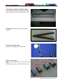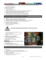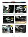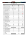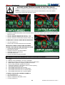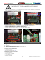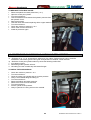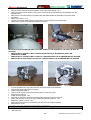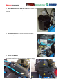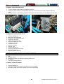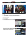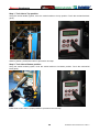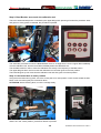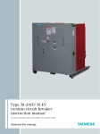
1
QUADRIGA
SERVICE MANUAL
DO NOT COPY NOR DISTRIBUTE
NO PART OF THIS DOCUMENT MAY BE PHOTOCOPIED, REPRODUCED, OR TRANSLATED
WITHOUT PRIOR WRITTEN CONSENT OF SNAP-ON
1
QUADRIGA Service Manual 02-10 Rev.C
UPDATING GUIDE:
REVISION C - February 2010
Updated parts of chapters:
3.1
Electric diagram
10.4
TO ADJUST THE TOOLS 1 AND 2 ALIGNMENT
10.6
TO CHECK THE ALIGNMENT
11
SERVICE CODES SECTION
(Added:C45, C55, C66, C83, C88 – Modified: C51, C89)
12
TROUBLE SHOOTING (Modified all chapter from “Fault12”)
REVISION B - September 2009
Updated parts of chapters :
2.1
TOOLS AND SPECIAL TOOLS REQUIRED
10.4
TOOLS 1 AND 2 ALIGNEMENT: CHECK AND ADJUSTMENT
11
SERVICE CODES SECTION
12
TROUBLE SHOOTING
Page, 8, 9, 10
Page, 93
Page, 95, 96
from Page, 98
from Page,124
Page, 7
Page, 7
Page, 7
Page, 7
________________________________________________________________________________________
REVISION A - June 2009
Issued first final edition on June 2009.
________________________________________________________________________________________
2
QUADRIGA Service Manual 02-10 Rev.C
TABLE OF CONTENTS
CHAPTER 1 INTRODUCTION
1.1
General
Pag.
Pag.
5
5
CHAPTER 2 TOOLS AND SAFETY
2.1
Tools and special tools required
2.2
Important safety instructions
2.3
Electrical safety precautions
Pag.
Pag.
Pag.
Pag.
5
5
7
7
CHAPTER 3 ELECTRIC, PNEUMATIC AND HYDRAULIC DIAGRAMS
3.1
Electric diagram
3.2
Pneumatic diagram
3.3
Hydraulic diagram
Pag.
Pag.
Pag.
Pag.
7
8
11
12
CHAPTER 4 AC/DC POWER DISTRIBUTION
4.1
Lockout and/or tagout system procedure
4.2
Electrical requirements
4.3
AC Theoy of operation
4.4
DC Theory of operation
Pag.
Pag.
Pag.
Pag.
Pag.
13
13
13
13
15
CHAPTER 5 ACCESS TO ELECTRIC AND ELECTRONIC COMPONENTS
5.1
Access to the electric box
5.2
Access to the control panel
5.3
Access Rotational switch
5.4
Access to hydraulic motor
5.5
Access to turntable motor and potentiometer
5.6
Access M1 and M2 VDC motors
5.7
Access to Bead breaker potentiometers
5.8
Access to sidewall bead breakers switches
5.9
Access to lifts potentiometers
5.10
Access to wheel diameter potentiometer
5.11
Access to tool 1 and 2 carriage potentiometer
Pag.
Pag.
Pag.
Pag.
Pag.
Pag.
Pag.
Pag.
Pag.
Pag.
Pag.
Pag.
19
19
19
20
20
20
21
22
22
23
23
24
CHAPTER 6 ELECTRIC SECTION
6.1
Power supply cable: check and replacement
6.2
Main switch Q2: check and replacement
6.3
Hydraulic motor cable: check and replacement
6.4
Hydralic motor: check and replacement
6.5
Fuses Q2 and Q3: check and replacement
6.6
Turntable motor cable: check and replacement
6.7
Turntable motor and belt: check and replacement
6.8
VDC motors M1 and M2: check and replacement
6.9
EMC inverter T1: check and replacement
6.10
Transformer T3: check and replacement
6.11
Fuses F3, F4, F5: check and replacement
6.12
Link converter: check and replacement
6.13
Control panel switches S5 to S13 and cable: check and replacement
6.14
Sidewall bead breaker micro switches: check and replacement
6.15
Coil connectors: check and replacement
6.16
Wheel clamp /unclamp switch: check and replacement
6.17
Turntable switch: check and replacement
Pag.
Pag.
Pag.
Pag.
Pag.
Pag.
Pag.
Pag.
Pag.
Pag.
Pag.
Pag.
Pag.
Pag.
Pag.
Pag.
Pag.
Pag.
25
25
26
27
27
29
30
31
32
33
34
34
35
35
37
38
39
40
CHAPTER 7 ELECTRONIC SECTION
7.1
EMC inverter: check and replacement
7.2
EMC inverter: set up
7.3
CPU board A1: check and replacement
7.4
Software installation: check and replacement
7.5
Dual DC drive motor board A2: check and replacement
7.6
Valves control board A3: check and replacement
7.7
Distance laser B3: check and replacement
7.8
Bead breaker potentiometer S3 and S4: check and replacement
Pag.
Pag.
Pag.
Pag.
Pag.
Pag.
Pag.
Pag.
Pag.
44
44
45
48
49
49
50
51
52
3
QUADRIGA Service Manual 02-10 Rev.C
7.9
7.10
7.11
7.12
7.13
Turnatble carriage potentiometer B1: check and replacement
Tools carriage potentiometer B2: check and replacement
Lift size potentiometer B6: check and replacement
Lift rotation potentiometer B5: check and replacement
Lift raising potentiometer B4: check and replacement
Pag.
Pag.
Pag.
Pag.
Pag.
53
54
55
56
57
CHAPTER 8 HYDRAULIC SECTION
8.0
Hydraulic function
8.1
Access to hydraulic parts
8.2
Hydraulic oil level: check and levelling
8.3
High hydraulic chuck pressure circuit: check and adjustment
8.4
Hydraulic pressure of centre post cylinder: check and adjustment
8.5
Centre post cylinder seals: check and replacement
8.6
Bead breakers cylinders: check and replacement
8.7
Bead breakers cylinder seals: check and replacement
8.8
Hydraulic pump: check and replacement
8.9
Coil valve: check and replacement
Pag.
Pag.
Pag.
Pag.
Pag.
Pag.
Pag.
Pag.
Pag.
Pag.
Pag.
58
58
59
59
60
60
62
66
67
69
70
CHAPTER 9 PNEUMATCI SECTION
9.0
Pneumatic function
9.1
Access to pneumatic components
9.2
Air filter – lubricator assy: check and replacement
9.3
Swinging tools cylinders: check and replacement
9.4
Rotational tool cylinder: check and replacement
9.5
Lift cylinder: check and replacement
9.6
Solenoids valve: check and replacement
9.7
MH cylinder: check and replacement
9.8
MH cylinder control valve: check and replacement
9.9
Inflation spool valve: check and replacement
9.10
bead blaster valve: check and replacement
Pag.
Pag.
Pag.
Pag.
Pag.
Pag.
Pag.
Pag.
Pag.
Pag.
Pag.
Pag.
72
72
73
76
77
79
80
81
82
84
84
86
CHAPTER 10 MECHNICAL SECTION
10.0
Mechanical section
10.1
Gear box: check and replacement
10.2
Lead screw nuts: check and replacement
10.3
Tool 1 and 2: check and replacement
10.4
Tool 1 and 2 alignment: check and adjustment
10.5
Bead breaker carriage: check and replacement
10.6
Bead breaker discs alignment: check and adjustment
10.7
Bead breaker arms spring: check and adjustment
Pag.
Pag.
Pag.
Pag.
Pag.
Pag.
Pag.
Pag.
Pag.
87
87
87
88
90
91
93
94
96
CHAPTER 11 SERVICE C CODES
Pag.
97
CHAPTER 12 TROUBLE SHOOTING
Pag.
123
CHAPTER 13 SERVICE BULLETINS
Pag.
127
4
QUADRIGA Service Manual 02-10 Rev.C
CHAPTER 1
INTRODUCTION
1.1 GENERAL
This Service Manual describes maintenance, check and repair operations of the Super automatic tire
changers based on Quadriga platform under Hofmann, John Bean and Boxer brands and is for use of
qualified and trained personnel only.
Keep this manual constantly updated, by adding Service Bulletins related to the tire changers.
IMPORTANT!
The identification datas of each machine are printed on a adhesive label attached to the cabinet of the
machines. The serial number is a sequence of figures standing for the manufacturing month and year the
first four numbers, followed by the machine part number made of 7 numbers and finally the progressive
serial number of the machine manufactured with this specific part number.
CHAPTER 2
TOOLS AND SAFETY
2.1 TOOLS AND SPECIAL TOOLS
To repair and/or check these tire changer, the following standard tools are required:
Keys
: 6mm to 30mm
Tube type keys
: 7mm to 17mm
Allen keys
: 2.5 mm to 12 mm
Socket wrenches
: 17mm to 24mm
Allen socket keys
: 8mm to 12mm
Screw drivers
: Flat bed and Phillips from 1 to 5
Multimeter
: AC, DC, A, Ohm, pF
Lotctite, silicon and mechanical extractor
Special tools that are required for specific tasks are:
Manometer with adapter:
# 4006849
Use this manometer to check the hydraulic pressure
5
QUADRIGA Service Manual 02-10 Rev.C
Calibration bar # 4031022 / EAS2111G63A :
Use this calibration fixture to perform all calibration
and to adjust the tools and the bead breaker rollers.
Calliper key: Use this key to open the hydraulic
cylinders.
Clock with magnetic base:
Use this tool to adjust the bead breaker disc.
Ring nut socket keys:
There are 4 different keys: 10mm, 17mm, 20mm and
25mm.
Use these keys to tight or loose the knees ring nuts.
6
QUADRIGA Service Manual 02-10 Rev.C
2.2 MPORTANT SAFETY INSTRUCTIONS
The units are CE or UL approved, but whenever using this equipment basic safety precautions should
always be followed, including the following:
1. Read all instructions.
2. Do not operate equipment with a damaged power cord or if the equipment has been damaged until it has
been examined by a qualified authorized service technician.
3. If an extension cord is used, a cord with a current rating equal to or more than that of the machine should
be used. Cords rated for less current than the equipment may overheat. Care should be taken to arrange
the cord so that it will not be tripped over or pulled.
4. Always unplug equipment from electrical outlet when not in use. Never use the cord to pull the plug from
the outlet. Grasp plug and pull to disconnect.
5. To reduce the risk of fire, do not operate equipment in the vicinity of open containers of flammable liquids
(gasoline).
6. Keep hair, loose fitting clothing, fingers and all parts of the body away from moving parts.
7. Adequate ventilation should be provided when working on operating internal combustion engines.
8. To reduce the risk of electric shock, do not use on wet surfaces or expose to rain.
9. Do not hammer on or hit any part of the control box and portable control.
10. Do not allow unauthorized personnel to operate the equipment.
11. Use only as described in this manual. Use only manufacturer’s recommended attachments.
12. Always securely lock the wheel before starting the operation.
13. ALWAYS WEAR SAFETY GLASSES. Everyday eyeglasses only have impact resistant lenses, they are
NOT safety glasses.
14. Quadriga tire changer is for indoor use only.
2.3 ELECTRICAL SAFETY PRECAUTIONS
Make sure the tire changer is unplugged before disconnecting any wires in preparation for replacing any
electric mechanic components, cables or other items within the unit
CHAPTER 3
ELECTRIC, HYDRAULIC AND PNEUMATIC DIAGRAMS
This session is related to the electric, hydraulic and pneumatic diagram configurations for CE and UL proved
machines.
7
QUADRIGA Service Manual 02-10 Rev.C
3.1 ELECTRIC DIAGRAM
8
QUADRIGA Service Manual 02-10 Rev.C
9
QUADRIGA Service Manual 02-10 Rev.C
10
QUADRIGA Service Manual 02-10 Rev.C
3.2 PNEUMATIC DIAGRAM
11
QUADRIGA Service Manual 02-10 Rev.C
3.3 HYDRAULIC DIAGRAM
12
QUADRIGA Service Manual 02-10 Rev.C
CHAPTER 4
AC/DC POWER DISTRIBUTION
4.1 LOCKOUT AND/OR TAGOUT SYSTEM PROCEDURE
1. Notify all affected employees that a lockout or tagout system is going to be utilized and why. The
authorized employee should know the electrical power the machine uses and it’s hazards.
2. If the machine or equipment is running, shut it down by the normal stopping procedure (depress the stop
button, open toggle switch, etc.)
3. Use appropriate devices to isolate the equipment from the power source(s). Stored energy (such as that in
springs, elevated machine members, rotating flywheels, hydraulic systems, and air gas, steam or water
pressure, etc.) must be dissipated or restrained by methods such as repositioning, blocking, bleeding down,
etc.
4. Lockout and/or tagout the energy isolating devices with individual lock(s) or tag(s).
5. After ensuring that no personnel are exposed, and as a check on having disconnected the energy
sources, operate the push button or other normal operating controls to make certain the equipment will not
operate. CAUTION: RETURN OPERATING CONTROL(S) TO “NEUTRAL” OR “OFF” POSITION AFTER
THE TEST [DE-ENERGIZED STATE].
6. The equipment is now locked out or tagged out.
4.2 ELECTRICAL REQUIREMENTS
NOTE: ANY ELECTRICAL WIRING MUST BE PERFORMED BY LICENSED PERSONNEL.
ALL SERVICE MUST BE PERFORMED BY AN AUTHORIZED SERVICE TECHNICIAN.
Check on the plate of the machine that the electrical specifications of the power source are the same as that
of the machine.
NOTE: ANY ELECTRICAL OUTLET INSTALLATION MUST BE VERIFIED BY A LICENSED
ELECTRICIAN BEFORE CONNECTING THE TIRE CHANGER.
NOTE: ENSURE THAT THE OUTLET HAS AN AUTOMATIC GROUND FAULT CIRCUIT BREAKER
WITH A DIFFERENTIAL CIRCUIT SET AT 30 MA.
4.3 AC THEORY OF OPERATIONS
Always use the “One Hand Rule” when working with AC voltages by keeping one hand in your pocket or
behind your back. Before removing wires from the tire changer, always verify that the unit is “OFF”. Turn off
the Main Power Switch on the back and unplug the AC power cord from the AC outlet.
AC DISTRIBUTION
All Quadriga tire changers are equipped by two VAC motors:
One 230 VAC single phase pump motor and one 230 VAC three phase turntable motor.
The voltage at which the machine is wired is printed on the serial number plate and on a tag at the end of the
power cord.
The power cord has 3 wires:
N
= Neutral
L1
= Phases
PE (yellow/green)
= Ground
The machines can work at 50 or 60 Hertz according the EMC inverter tab position.
The 230 (+/-10%) AC voltage comes in through a “ON/OFF” Front Panel Power Switch Q1 and immediately
is sent via the 20A fuses holder Q2 to an anti disturb filter to the EMC Inverter.
The units supplied at 100/115 VAC are equipped by a transformer before the inverter and do not have the
anti disturb filter.
The 230 VAC is then sent to a terminal to be distributed to the following components:
13
QUADRIGA Service Manual 02-10 Rev.C
TRANSFORMER T3
It transforms the 230VAC in 40VACto supply the
horizontal centre post and the tools carriages and the
electronic boards A1, A2 and A3. The 40VAC output
goes, through the 20A fuses holder, to the rectifier V1.
EMC INVERTER T1
It supplies 230/3 to the turntable motor M3 and change
the motor rotational speed from 50 to 100Hz.
TURNTABLE MOTOR M3
It is 3 phase single speed motor and it is supplied by
the inverter that also change the rotational speed.
14
QUADRIGA Service Manual 02-10 Rev.C
HYDRAULIC PUMP MOTOR M4
It is 230 VAC single phase motor. N and PE wires
directly go to the motor while L1 goes through
electronic of the X39 connector on the Coil Valves
Controls Board A3 to control the automatic shutting
off / turning on.
4.4 VDC THEORY OF OPERATIONS
LINK CONVERTER V1
Link converter transforms the 40VAC input into 48VDC to
be supply the following components:
Dual DC Drive Motors board A2 for the
horizontal centre post and the tools carriages VDC
motors.
Valves Control Board A3
PROCESSOR BOARD A1
The processor board A1 (CPU) is placed into the
control panel and manages all input form
joystick switches, rotational pedal, Distance laser
sensor, potentiometers, keypad and LCD display. The
24 VDC operating voltage comes to X21 connector
from X37 one of the Coil Valves Controls Board A3.
The CPU board A1 communicate with all other board
via serial communication RS 485 (connector X20). The software can be updated with the flash card like on
the balancer.
All switches of the control platform are connected to
the CPU board trough connector X24, X25 and X26.
The software update can be done with an SD card like
on the balancers
DUAL DC DRIVE MOTOR BOARD A2
The Dual DC Drive Motors board supplies the 48 VCC to the horizontal carriage sliding motor M1 (connector
X32) and to the carriage tools motor M2 (connector X35) and, controlled by the CPU, it allows to control the
motor acceleration and deceleration.
15
QUADRIGA Service Manual 02-10 Rev.C
It is directly supplied with 48 VDC by the rectifier V1 with the wider wires (connector X34) and there is also
an input for 24 VDC (connector X33).
It communicates with the CPU board A1 via serial communication RS 485 (connector X27).
VALVES CONTROL BOARD A3
The Valves Control Board A3 controls the hydraulic
and the pneumatic coil valves, and the pump motor M4
automatic shutting off / turning on, connector X39. It is
directly supplied with 48 VDC (connector X37) from the
rectifier V1 with the smaller wires and it also
transforms 48 VDC in 24 VDC (connector X37) for the
logical control part of Dual DC Drive Motors board A2
and for the CPU board A1.
On this board there are the 3 control signals for the
inverter T1 driving:
X42 slow speed clock wise rotational direction.
X40+X42 for high speed clock wise rotational direction.
X43 slow speed counter clock wise rotational direction.
This board communicates with the CPU board A1 via
serial communication RS 485 (connector X36).
The first 6 output of the connector X45 to 65 goes to the hydraulic coil valve, while all other ones are directed
to the pneumatic.
VDC MOTORS M1 AND M2
These motors control the movement of the horizontal centre post and the tools carriages. They are supplied
at 48VDC from the Dual DC Drive Motors board.
16
QUADRIGA Service Manual 02-10 Rev.C
BEAD BREAKERS LINEAR POTENTIOMETERS B7 AND B8
The bead breakers potentiometers B7 and B8 are 5K
linear type. They are supplied 5,20 VDC from the CPU
board A1. This input voltage can be measured at the
Processor Board X6 to X19 pin. The output voltage is
dependent upon the deflection of the gauge from the
home position.
CENTRE POST CARRIAGE POTENTIOMETER B1
The bead breakers potentiometers B1 is 5K linear type.
It is supplied 5,20 VDC from the Dual DC motor driver
board and its input voltage can be measured at the X29
connector. The output voltage is dependent upon the
deflection of the gauge from the home position.
TOOL 1 - 2 CARRIAGE POTENTIOMETER B2
This potentiometer is 10K 10 turns rotational type. It is
supplied 5,20 VDC from the Dual DC motor driver board
and its input voltage can be measured at the X28
connector. The output voltage is dependent upon the
rotation of the gauge from the home position.
LIFTS AND WHEEL DIAMETER POTENTIOMETERS B4, B5 AND B6
The lifts and wheel diameter potentiometers are 5K rotational type. They are supplied 5,20 VDC from the
CPU board A1 and their input voltage can be measured at the CPU board A1 X6 to X19 pin. The output
voltage is dependent upon the deflection of the gauge from the home position.
17
QUADRIGA Service Manual 02-10 Rev.C
DISTANCE LASER SENSOR B3
The distance laser sensor measures the horizontal
position of the rim compared to the tools and check the
rim shape. It is supplied by the CPU board A1 connector
X89.
LCD DISPLAY A4
The Display Board receives 5,20 VDC from the Main
Processor Board A1. This 5,20 volts can be checked on
the CPU board A1 X3 connector.
KEYPAD S2
The keypad allows operator input to the Main Processor
Board. The output signal directly goes to the CPU board
A1 connector X2.
18
QUADRIGA Service Manual 02-10 Rev.C
CHAPTER 5
ACCESS TO ELECTRIC AND ELECTRONIC COMPONENTS
To access to electric parts of the machine:
5.1 ACCESS TO ELECTRIC BOX: Turn the machine off and unplug it from the wall. Open the box by
using the key. Sometimes the opening may result difficult because of door seal sticking: when this
happens the door can be easily opened by pulling it with both hands from top and bottom.
On the door panel there are all radio control devices and the “side to side” tool control. Inside of the box
there are all other electric components.
5.2 ACCESS TO THE CONTROL PANEL: Remove the screws and lift up the cover to get the access
to all switches and to the QCPU board.
19
QUADRIGA Service Manual 02-10 Rev.C
5.3 ACCESS TO THE ROTATIONAL SWITCH: Remove the two front screws and open the pedal assy
cover.
IMPORTANT: WHEN REMOUNTING SWITCHES AND CLOSING THE ELCTRIC BOX DOOR BE
CAREFUL NOT TO CRUSH WIRES.
5.4 ACCESS TO THE HYDRAULIC MOTOR: Remove the plastic cover to access to the hydraulic motor.
5.5 ACCESS TO THE TURNTABLE MOTOR AND POTENTIOMETER: Remove the lifts cylinders
plastic protections.
20
QUADRIGA Service Manual 02-10 Rev.C
Remove the mobile plastic top cover. Go in C62 and raise the vertical lift.
Loosen the top cover screws and remove the cover from the front.
Then remove from the back the second half of the cover. The turntable motor and the potentiometer are
now available.
5.6 ACCESS TO THE M1 AND M2 VDC MOTORS: The access to these motors is very easy because
they covered by a plastic protection easily accessible.
21
QUADRIGA Service Manual 02-10 Rev.C
5.7 ACCESS TO THE BEAD BREAKERS
POTENTIOMETERS: The bead
breakers potentiometers are placed behind of the
related hydraulic cylinders and therefore the access
requires the dismounting of these cylinders.
5.8 ACCESS TO THE SIDEWALL BEAD
BREAKERS SWITCHES:
These switches are easily accessible because they
are directly bolted to the bead breaker carriages.
22
QUADRIGA Service Manual 02-10 Rev.C
5.9 LIFTS POTENTIOMETERS: Remove the lifts cylinders plastic protections.
5.10 ACCESS TO THE WHEEL DIAMETER POTENTIOMETER: This potentiometer is installed on the
front rotational lift. Remove the plastic cover to access
23
QUADRIGA Service Manual 02-10 Rev.C
5.11 ACCESS TO THE TOOL 1 - 2 CARRIAGE
POTENTIOMETER :
The access to this potentiometer is easy because it is
available in the back side of the tools carriage.
24
QUADRIGA Service Manual 02-10 Rev.C
CHAPTER 6
ELECTRIC SECTION
WARNING!
BEFORE APPROACHING THE ELECTRIC PARTS OF THE MACHINE,
DISCONNECT THE MACHINE FROM ELECTRIC SUPPLY
Very often electric failures are only caused by loosened wires or connectors not well fitted.
Therefore it is VERY IMPORTANT BEFORE STARTING WITH ANY CONTROL AND/OR REPLACEMENT
VERIFY IF ALL WIRES AND CONNECTORS ARE WELL FITTED.
6.1 POWER SUPPLY CABLE AND PLUG: CHECK AND REPLACEMENT
: 1h
: Small and medium screwdriver, medium cross screwdriver, faston pliers, scissors, pliers, multimeter.
L : Defective power supply cable and plug may cause the following malfunction:
1. Turning the switch on the machine does not run at all.
TO CHECK THE CABLE:
Disconnect power supply.
Open the electric box 5.1.
Disconnect the wires form the switch.
Check wires continuity from power supply plug to main switch wires terminals.
IMPORTANT! TO CHECK GROUND (YELLOW/GREEN) WIRE, DISCONNECT THE WIRE END FROM
THE TERMINAL BLOCK.
TO REPLACE THE CABLE:
Disconnect the power supply.
Remove the main switch and disconnect the wires.
Disconnect the ground wire from terminal block.
Release cable strain relief on the electric box.
Remove plug from cord and take the defective cable away.
Insert the new cable through the strain relief.
IMPORTANT!
USE ONLY APPROVED CABLES AND PLUGS AND GROUND WIRE MUST BE LONGER THAN THE
OTHER ONES.
Fix new fastons on inside cable ends and connect them to the switch terminals.
Fix the main switch.
25
QUADRIGA Service Manual 02-10 Rev.C
Connect the ground wire to ground terminal block.
Install plug.
Tighten strain relief FIRMLY.
6.2 MAIN SWITCH Q1: CHECK AND REPLACEMENT
: 30’
: Medium cross crewdrivers and pliers.
L : Defective main switch may cause the following malfunction:
1. Turning the switch on the machine does not run at all.
TO CHECK THE SWITCH:
Disconnect power supply.
Open the control panel 5.1.
Disconnect all wires from the main switch and
remove it with a screwdriver.
Turn switch to “Off”. Check that there is no
Continuity (Ω =infinity) between any terminals 1,2,3
And 4.
Turn switch to “On”. Check that there is continuity
between terminals (Ω = 0 ~ 0,3) and discontinuity
between terminals 1-3 and 1-4, as well as 2-3 and 2-4
If there is continuity the switch is in short circuit and
It must be replaced.
TO REPLACE THE SWITCH:
Remove the cover and loosen the screw to remove
Switch knob.
Remove the disc acting with a screwdriver on the
side tabs
Loosen the screws and remove the frame switch.
Install the new main switch
Check that the tabs for contacts on the new switch
are correctly oriented.
Connect wires ends FIRMLY to the new switch
terminals as shown in the appropriate electric
diagram ( 3.0).
Mount the switch frame.
Install the disc.
Mount again the switch knob and cover the screw.
26
QUADRIGA Service Manual 02-10 Rev.C
6.3 HYDRAULIC MOTOR CABLE: CHECK AND REPLACEMENT
L
1.
2.
3.
: 1h
: Medium screwdriver, medium cross screwdriver, 7mm tube type key, 5mm allen key, multimeter, pliers.
: Defective cable may cause the following malfunction:
Low motor and hydraulic power.
Noisy motor.
Motor damaging (burning).
TO CHECK THE CABLE:
Disconnect power supply.
Open the electric box ( 5.1).
Remove the top cover protection.
WARNING!
THE CONDENSER COULD BE STILL CHARGED OF POWER SUPPLY.
SHORT CIRCUIT ALL THE WIRES BEFORE DISCONNECTING TO PREVENT
ANY ELECTRIC SHOCK
Remove the motor terminals cover and remove all wires from terminals.
Disconnect the wires from all terminals and L1 wire from the connector X39 of the Valves control board
A3
Select the multimeter in Ohm and check if there is continuity between ends of each wire.
TO REPLACE THE CABLE:
Release cable strain relief on the electric box and on the motor.
Take the wrong cable away.
Insert the new cable through the strain relief.
IMPORTANT! : USE ONLY APPROVED CABLE AND GROUND WIRE MUST BE LONGER THAN THE
OTHER ONES.
NOTE: Before connecting the wires ends, tighten all terminals nuts on the motor.
Fix new fastons on inside cable ends and connect them to the motor and breaker terminals.
WARNING!
THE CONDENSER COULD BE STILL CHARGED OF POWER SUPPLY.
SHORT CIRCUIT ALL THE WIRES BEFORE DISCONNECTING TO PREVENT
ANY ELECTRIC SHOCK
Check the rotation way of the motor: If it is wrong reverse only L1 with one of condenser wires otherwise
the chuck motor will turn wrongly.
Mount the motor terminals cover.
IMPORTANT: WHEN REMOUNTING THE MOTOR TERMINALS COVER BE CAREFUL NOT TO
CRUSH WIRES.
Mount the top cover protection.
6.4 HYDRAULIC MOTOR: CHECK AND REPLACEMENT
L
1.
2.
3.
: 2h
: 7mm tube type wrench, 5mm allen key, madium standard screwdriver, medium cross screwdriver,
multimeter, rubber hammer, calliper.
: Defective hydraulic motor may cause the following malfunction:
Turning the switch on the hydraulic motor does not run at all.
Motor stops when high hydraulic pressure is required.
Motor noisy.
27
QUADRIGA Service Manual 02-10 Rev.C
4. Turning the switch on the motor turns but the machine does not make any hydraulic movements.
5. The shops safety switch shuts off whenever the motor runs.
IMPORTANT!
IN CASE OF FAILURE #4 CHECK IF THE ROTATION OF THE MOTOR IS CORRECT AS FIRST.
TO CONTROL THE MOTOR WHEN IT DOES NOT RUN:
Disconnect power supply.
Remove the top cover protection of the hydraulic assy.
Remove the motor terminals cover.
WARNING!
THE CAPACITOR COULD BE STILL CHARGED OF POWER SUPPLY.
SHORT CIRCUIT ALL THE WIRES BEFORE DISCONNECTING TO PREVENT
ANY ELECTRIC SHOCK
Disconnect the capacitor wires from the terminals
Select the multimeter in Ohm and, positioning one
probe on the motor cabinet, check the continuity of
all other terminals of the motor: if one or more values
are close to “0” the motor is in short circuit.
TO CONTROL THE MOTOR WHEN IT IS NOISY:
Disconnect power supply.
Remove the top cover protection of the hydraulic assy.
Remove the motor fan protection and check if the fan is well tightened on the shaft.
Mount the motor fan protection.
Remove the motor terminal cover and verify if all wires are well fitted on terminals.
WARNING!
THE CAPACITOR COULD BE STILL CHARGED OF POWER SUPPLY.
SHORT CIRCUIT ALL THE WIRES BEFORE DISCONNECTING TO PREVENT
ANY ELECTRIC SHOCK
If the wires are well fitted on terminals mount the motor terminals cover and remove the 4 motor
screws very carefully: the motor may fall down suddenly.
Place the motor on the floor.
Switch the motor on and listen it: if it is noisy replace it by following next step.
TO REPLACE THE MOTOR:
Remove all wires from the motor.
Remove the 4 motor screws very carefully: the motor may fall down suddenly.
Remove the aluminium spacer.
Take the distance of the joint compared to the motor by using a calliper.
Remove it from the motor shaft by using two levers.
28
QUADRIGA Service Manual 02-10 Rev.C
Take the new motor.
Mount the joint following the distance previously verified and lock it.
IMPORTANT!
A WRONG ADJUSTMENT OF THE JOINTS WILL CAUSE HYDRAULIC PUMP DAMAGING OR
DAMAGING OF JOINTS THEMSELVES WITH A CONSEGUENT NO HYDRAULIC MOVEMENTS.
Mount the aluminium spacer: There is a little hole in a face and this face must be mounted downwards in
order to show immediately if there is an inner oil leaking.
Mount the motor on the hydraulic assy.
Connect the wires FIRMLY to motor terminals following the voltage at which the machine is supplied.
NOTE: Before connecting the wires ends, tighten all terminals nuts.
WARNING!
THE CONDENSER COULD BE STILL CHARGED OF POWER SUPPLY.
SHORT CIRCUIT ALL THE WIRES BEFORE DISCONNECTING TO PREVENT
ANY ELECTRIC SHOCK
Check the rotation way of the motor: If it is wrong reverse only L1 with one of condenser wires otherwise
the chuck motor will turn wrongly.
Mount the motor terminals cover.
IMPORTANT: WHEN REMOUNTING THE MOTOR TERMINALS COVER BE CAREFUL NOT TO
CRUSH WIRES.
Mount the top cover protection.
6.5 Q2 AND Q3 FUSES : CHECK AND REPLACEMENT
: 30’
: Multimeter
L : Defective fuse/s may cause the following malfunction:
1. Machine does not turn on
2. Machie does not wwork.
TO CONTROL AND REPLACE THE FUSES:
Disconnect the machine from power supply.
Open the electric box ( 5.1).
Open the protection and remove the fuse.
Verify if there is continuity between the ends of each fuse.
29
QUADRIGA Service Manual 02-10 Rev.C
If necessary, replace them with fuses of the same value: 20A.
6.6 TURNTABLE MOTOR CABLE: CHECK AND REPLACEMENT
L
1.
2.
3.
4.
: 1h
: Medium screwdrivers, medium cross screwdrivers, 7mm tube type wrench, pliers, multimeter
: Defective chuck motor cable may cause the following malfunction:
Low chuck power.
Noisy motor.
Fuses F1,F2,F3 blow up.
Motor damaging (burning).
TO CHECK THE CABLE:
Remove all covers ( 5.1).
Disconnect power supply.
Open the electric box ( 5.1).
Loosen the front screw to remove the front inverter cover and disconnect the blue, brown and black
motor wires in bottom of the inverter.
Remove the motor terminals cover and all wires from terminals.
Select the multimeter in Ohm and check if there is continuity between ends of each wire.
TO REPLACE THE CABLE:
Release cable strain relief on the electric box and on the motor.
30
QUADRIGA Service Manual 02-10 Rev.C
Take the wrong cable away.
Insert the new cable through the strain relief.
IMPORTANT!
USE ONLY APPROVED CABLE AND GROUND WIRE MUST BE LITTLE LONGER THAN THE OTHER
ONES.
NOTE: Before connecting the wires ends, tighten all terminals nuts on the motor.
Fix new fastons on inside cable ends and connect them to the motor and three polar meter terminals.
Check the rotation way of the motor: If it is wrong reverse only two motor wires.
Mount the motor terminals cover.
IMPORTANT: WHEN REMOUNTING THE MOTOR TERMINALS COVER BE CAREFUL NOT TO
CRUSH WIRES.
6.7 TURNTABLE MOTOR AND BELT: CHECK AND REPLACEMENT
L
1.
2.
3.
: 1h 30’
: End keys 13,17mm, medium cross screwdriver, 7mm tube type wrenches, multimeter, loctite, extractor.
: Defective chuck motor may cause the following malfunction:
Low turntable power.
Motor is noisy.
Motor is burnt.
TO CONTROL THE TURNTABLE MOTOR WHEN IT SHOWS LOW POWER:
Disconnect machine from power supply.
Remove the motor terminals cover ( 5.1).
Switch the machine on.
MACHINE UNDER TENSION DANGER OF ELECTRIC SHOCK
Take the multimeter and select it in VAC.
Position the multimeter probes on U1 and W1 of the motor terminals and press the rotation pedal
If the display shows the voltage at which the machine is supplied the motor must be replaced.
Perform the same controls with terminals U1-V1 and W1-V1.
TO CONTROL THE TURNTABLE MOTOR AND THE BELT IF NOISY:
Disconnect machine from power supply.
Remove the motor terminal cover and verify if all wires are well fitted on the terminals.
If the wires are well fitted on terminals, mount the motor terminals
Loosen the 12mm nuts to get motor lose and remove the belt.
31
QUADRIGA Service Manual 02-10 Rev.C
Remove the fan protection and verify if its well tightened on motor shaft.
Mount the fan protection, turn the machine on, make the turntable motor turning and verify if it s noisy.
TO REPLACE THE TURNTABLE MOTOR:
Remove the steel protection and loosen the two bolts that hold the motor. Pls. pay attention because the
motor could fall down suddenly.
Remove the pulley set screws.
Remove the pulley by using an extractor tool.
Remove the motor from the support.
Take the new motor.
Install the pulley by using rubber hammer.
NOTE: The mounting of the new pulley must be done very
carefully in order to avoid motor bearings damaging.
Install the motor on its support.
Install the motor assy on the machine and lock it
Firmly..
Mount the new belt.
Adjust the belt tension
Connect the wires FIRMLY to motor terminals
following the voltage at which the machine is supplied.
NOTE: Before connecting the wires ends, tighten all terminals nuts.
Turn the machine on and check the parameter 09 of the inverter T1 that must be 0.75.
Check the rotation way of the motor: If it is wrong reverse only two chuck motor wires.
Mount the motor terminals cover.
IMPORTANT: WHEN REMOUNTING THE MOTOR TERMINALS COVER BE CAREFUL NOT TO
CRUSH WIRES.
Mount all protections.
6.8 VDC MOTORS M1 AND M2: CHECK AND REPLACEMENT
: 1h each one
: Multimeter, allen key 4 and 5mm, small and medium cross screwdrivers.
L : Defective VDC motors may cause the following malfunction:
1. Turntable does not slide left and and right.
2. Tools carriage does not go up and down.
TO CONTROL THE MOTORS:
Disconnect machine from power supply.
32
QUADRIGA Service Manual 02-10 Rev.C
Remove the motors plastic protection ( 5.1).
Unplug the motors connectors.
Take the multimeter and select it in VDC.
Turn the machine on.
MACHINE UNDER TENSION DANGER OF ELECTRIC SHOCK
Position the multimeter probes on the connector terminals coming from the electric box.
Press the switch: if the multimeter shows 48VDC but the motors do not run, the motors are defective and
must be replaced.
TO REPLACE THE MOTORS:
Turn the machine off.
Disconnect machine from power supply.
Loosen the four screws motor.
Remove the belt and the motor.
Remove the pulley from defective motor and install it
On the new one.
Mount the new motor and the belt.
Pull the motor together with belt.
When the is well tensioned lock the four screws FIRMLY.
Plug the connectors.
Check if the motor works fine.
Mount all protections.
6.9 EMC INVERTER T1: CHECK AND REPLACEMENT
L
3.
4.
5.
6.
7.
: 30’
: Multimeter, small and medium cross screwdrivers, pliers.
: Defective inverter may cause the following malfunction:
Turntable motor does not turn at all.
Turntable motor turns in slow speed only
Turntable motor turns in high speed only.
Turntable motor turns in reverse direction only.
The shut off switch of the tire shop shuts off.
TO CONTROL THE INVERTER:
Turn the machine on.
33
QUADRIGA Service Manual 02-10 Rev.C
Press the rotational pedal: if the motor does not run or if the tire shop shut off switch shuts off, the
inverter must be replaced.
TO REPLACE THE INVERTER:
Turn the machine off.
Open the electric box ( 5.1).
Loosen the screw and remove the front cover to access to the terminals ( 5.7).
Disconnect the wires from the inverter terminals marking the position.
Loosen the 4 screws in the back to remove the inverter.
Install the new inverter and wire it again as it was at the beginning
Turn the machine on and check the inverter set up of the red values.
6.10 TRANFORMER T3: CHECK AND REPLACEMENT
: 30’
: Multimeter, small and medium cross screwdrivers, pliers.
L : Defective transformer may cause the following malfunction:
8. Smoke gets out from the electric box with consequent burning of the transformer.
9. Turning the machine on, the machine does not make any movement.
TO CONTROL THE TRANSFORMER:
Take the multimeter and select it in VAC.
Switch the machine on.
MACHINE UNDER TENSION DANGER OF ELECTRIC SHOCK
Verify if the input among the terminals 0 – 230 is
correct. If not go to 5.2.
Verify if the output among terminals 0 and 40 is
correct.
TO REPLACE THE TRANFORMER:
Disconnect the machine from power supply.
Open the electric box ( 5.1).
Remove all wires from terminals.
IMPORTANT!
MARK WIRES PROPERLY FOR AN EASY AND SAFE
INSTALLATION.
Loosen its four screws.
Pull the transformer up and take it out.
Install the new transformer and tighten firmly all wires.
6.11 FUSES F3, F4,F5: CHECK AND REPLACEMENT
: 5’
: Multimeter.
L : Defective fuses may cause the following malfunction:
Turning the machine on, the machine does not make any movement.
TO CONTROL THE FUSES:
Disconnect the machine from power supply.
Open the electric box ( 5.1).
34
QUADRIGA Service Manual 02-10 Rev.C
Pull out the fuse holder by hand from the transformer.
Verify if there is continuity between the ends of each fuse.
If necessary, replace them with fuses of the same value: 6.3A 250Volts.
6.12 LINK CONVERTER: CHECK AND REPLACEMENT
: 30’
: Multimeter, Medium cross screwdriver
L : Defective rectifier may cause the following malfunction
1. Turning the machine on, the hydraulic motor run but the machine does not make any movement.
TO CONTROL THE CONVERTER:
Switch the machine on.
Take the multimeter and select it in VAC.
MACHINE UNDER TENSION. DANGER OF ELECTRIC SHOCK
Position the multimeter probes on the single black wire terminals of the converter and verify if the power
displayed by the multimeter is 40 VAC.
Position the multimeter probes on the double wires
terminals of the converter and verify if the power
displayed by the multimeter is 48 VDC : if not replace
the converter.
TO REPLACE THE CONVERTER:
Disconnect the machine from power supply.
Open the electric box ( 5.1).
Remove all wires from the converter.
IMPORTANT!
MARK WIRES PROPERLY FOR AN EASY AND SAFE
INSTALLATION.
Lose the defective converter and replace it with a
new one.
Fix all wires again.
6.13 CONTROL PANEL SWITCHES S5, S6, S7, S8, S9, S10, S11, S12, S13 AND
CABLES: CHECK AND REPLACEMENT
: 1h each one
35
QUADRIGA Service Manual 02-10 Rev.C
: Small and medium screwdriver, medium cross screwdriver, allen key 4 and 5mm
L : Defective control panel switch may cause the following malfunction:
1. Turning the machine on it does not make one or more movements.
IMPORTANT!
FAILURE MAY ALSO BE CAUSED BY HYDRAULIC OR
PNEUMATIC REASON. TO VERIFY IF THE FAILURE IS ELECTRIC
OR HYDRAULIC / PNEUMATIC PRESS THE COIL VALVE
CORRESPONDENTS TO THE DEFECTIVE HYDRAULIC /
PNEUMATIC MOVEMENT. IF THE MACHINE WORKS NORMALLY
BY PRESSING THE COIL VALVE, THE PROBLEM IS DUE TO AN
ELECTRIC MALFUNCTION.
TO CONTROL THE WIRES:
Turn the machine on and go in C61 ( 12) to check which switch
Is not working.
Disconnect the machine from power supply.
Open the control panel ( 5.1).
Remove the suspected defective wire from the related switch.
Remove the related connector from the CPU board.
Take a multimeter and select it in Ohm.
Check if there is continuity between the two ends of the suspected
bad cable.
TO REPLACE THE CABLE:
Disconnect all wires from the switches.
Disconnect both connectors from the CPU board.
Take the wires assy and connect all wires to the switches.
Connect the connectors to the CPU board.
Turn the machine on and check if it works normally
Mount the control panel again.
TO CONTROL THE SWITCHES:
Disconnect the machine from power supply.
Open the control panel ( 5.1).
IMPORTANT!
BEFORE STARTING WITH ANY REPLACEMENT VERIFY IF THE WIRES ARE WELL FITTED TO THE
TERMINALS AND IF THE SWITCH IS MECHANICALLY WELL MOUNTED.
36
QUADRIGA Service Manual 02-10 Rev.C
Remove the wires from the suspected defective
switch.
Take a multimeter and select it in Ohm
Position the multimeter probes on the switch terminals
and press the switch. If there is not continuity the switch
must be replaced.
If there is not continuity the switch must be replaced.
TO REPLACE THE SWITCHES:
Take the screwdriver and lift the switch tab to
remove the defective switch.
Install the new switch and connect the wires.
Turn the machine on and check if it works fine.
Mount the control panel again.
IMPORTANT: WHEN REMOUNTING THE CONTROL PANEL BE CAREFUL TO DO NOT CRUSH
WIRES.
6.14 SIDEWALL BEAD BREAKER MICRO SWITCHES S3 – S4 AND CABLE: CHECK
AND REPLACEMENT
: 1h
: Small and medium screwdriver, 4mm allen key.
L : Defective sidewall bead breaker switches may cause the following malfunction:
1. Display shows “Upper/lower bead breaker error” during bead breaking
2. Machine does not perform the bead breaking operation.
IMPORTANT! BEFORE STARTING WITH ANY REPLACEMENT VERIFY IF THE WIRES SWITCH IS
WELL FITTED, IF THE SWITCH IS MECHANICALLY IN GOOD CONDITION AND CORRECTLY
ADJUSTED.
TO CHECK THE SWITCH:
Turn the machine off and unplug it from the wall.
Press the micro switch to verify if it make the “click”: If not replace it.
Check if the micro switch is correctly adjusted: if not adjust it.
Check if the bead breaker arm is correctly adjusted if not adjusted ( 10).
Open the electric box ( 5.1).
Open the Control panel ( 5.1).
Unplug the connector X90 or X91.
Take a multimeter and select it in Ohm.
Position the multimeter probes on the wires ends of the supposed defective switch.
Press the switch and verify if there is continuity: If not the switch must be replaced.
37
QUADRIGA Service Manual 02-10 Rev.C
TO CHECK THE SWITCH CABLE:
Unplug the connector X23 from the CPU board
Take a multimeter and select it in Ohm.
Position the multimeter probes on the wires ends of
the supposed defective cable on the connectors X23
and X90 or X91 and verify if there is continuity:
If not replace the cable.
TO REPLACE THE SWITCH CABLE:
Remove the defective cable.
Route the new cable and plug it to the switch and
CPU board connector.
Turn the machine and check if it works fine
Mount the control panel again.
IMPORTANT: WHEN REMOUNTING THE CONTROL PANEL BE CAREFUL TO DO NOT CRUSH
WIRES.
TO REPLACE THE SWITCH
Remove the defective switch from the support.
Mount the new switch on the support without lock the screws.
Push the bead breaker arm up ‘til end of stroke and make sure that the micro switch tab is close to
switch end stroke.
Lock the switch screws FIRMLY.
Route again the cable.
Plug the connector to the cable.
Perform the Calibration step C80 ( 12).
Check if the machine works fine again.
Mount the control panel.
IMPORTANT: WHEN REMOUNTING THE CONTROL PANEL BE CAREFUL TO DO NOT CRUSH
WIRES.
6.15 COIL CONNECTOR CABLE: CHECK AND REPLACEMENT
: 1h
: Small standard and cross screwdrivers, pliers, multimeter.
L : Defective cable or connector may cause the following malfunction:
1. One or more hydraulic/pneumatic movements do not work.
38
QUADRIGA Service Manual 02-10 Rev.C
2. Fuse blows up.
TO CONTROL THE CABLE:
Disconnect the machine from power supply.
Open the electric box
Remove the plastic cover ( 5.1).
Remove all coil connector from coil valves.
Take a multimeter and select it in Ohm.
Position the multimeter probes on the ends of the coil
connector and verify if there is continuity between the
terminals: If there is not continuity the wires are defective.
TO REPLACE THE CABLE:
Disconnect all wires from the terminals block.
Disconnect all connectors from coil valves.
Release the cable strains relief.
Lift up the connectors by using a screwdriver to have
access to the wires.
IMPORTANT!
VERIFY IF THE WIRES ARE FITTED ON THEIR TERMINALS. IF THEY AREN’T TIGHTEN THEM FIRMLY
TO THE TERMINALS, MOUNT THE CONNECTOR AGAIN AND VERIFY IF THE MACHINE WORKS FINE.
IF THE PROBLEM IS NOT SOLVED YET PROCED FOLLOWING THE BELOW INSTRUCTION.
Remove all wires from connectors.
Take away the defective cable.
Insert the new cable.
Tighten all wires FIRMLY on the terminals block and on the coil connectors.
Tighten the cable strains relief.
Fix the connectors to the coil valve following the correct order.
Turn the machine on and check if it works fine.
Mount the plastic cover again.
6.16 WHEEL CLAMP / UNCLAMP SWITCH S14: CHECK AND REPLACEMENT
: 1h
: Small standard and cross screwdrivers, 5 mm allen key.
L : Defective wheel clamp/unclamp switch may cause the following malfunction:
1. The machine does not clamp or unclamp the wheels.
TO CHECK THE SWITCH
Turn the machine on and go in C61 ( 12) to check which switch is not working.
Turn the machine off.
Remove the pedal assy cover ( 5.1).
Make sure that the switch is mechanically in good condition and makes a “click”
39
QUADRIGA Service Manual 02-10 Rev.C
Press and push the pedal to make sure that the switch is well adjusted: if not make a new adjustment
Take a multimeter and select it in Ohm.
Unplug the connector X43.
Position the multimeter probes on the switch wires ends and press/push the pedal to verify if there is
continuity: if not the switch must be replaced.
TO REPLACE AND AJUST THE SWITCH:
Loosen the switch screws and remove the defective switch.
Mount the new switch without lock.
Push up/ press the pedal ‘til end of stroke and make sure that the micro switch tab is close to switch end
stroke. If the switch tab reach the end of stroke before the pedal, loosen the switch support screws and
make the adjustment
Lock the switch screws FIRMLY.
Route again the cable.
Plug the connector to the cable.
Check if the machine works fine again.
Mount the pedal assy cover again.
6.17 TURNTABLE SWITCH S1: CHECK, ADJUSTMENT AND REPLACEMENT
L
1.
2.
3.
4.
: 1h
: Small standard and cross screwdrivers, 5 mm allen key, 8mm key.
: Defective turntable switch may cause the following malfunction:
The turntable does not turn at all.
The turntable does not turn in first speed.
The turntable does not turn in second speed
The turntable does not in reverse speed.
TO CHECK THE SWITCH
Turn the machine off.
Remove the pedal assy cover ( 5.1).
Make sure that the switch is mechanically in good condition.
Press or push the pedal to make sure that the switch is properly adjusted: if not make a new adjustment
Disconnect the wires from the switch terminals.
IMPORTANT! MARK WIRES PROPERLY FOR AN EASY AND SAFE INSTALLATION
Take a multimeter and select it in Ohm.
In case the motor does not turn in first speed, position the multimeter probes on terminals 1 and 4 and
press the pedal to verify if there continuity. If not replace the switch.
40
QUADRIGA Service Manual 02-10 Rev.C
In case the motor does not turn in second speed, position the multimeter probes on terminals 1 - 4 and
1-8 and press the pedal to verify if there continuity. If not replace the switch.
In case the motor does not turn in reversed speed, position the multimeter probes on terminals 1-8 and
push up the pedal to verify if there continuity. If not replace the switch
TO ADJUST THE SWITCH:
41
QUADRIGA Service Manual 02-10 Rev.C
Make sure that the bar is more or less in the middle of the switch lever button-hole when the switch is in
rest position.
If it is not in the middle loosen the nut #1 and remove the bolts #2.
Turn half of a turn the spacer #3 and check if it is in the correct position.
Press the pedal all way down and make sure that switch has already switched to the second step before
the pedal has reached the end of stroke. The gap between the pedal and pedal assy cabinet must be
about 2mm.
Push the pedal all way up and make sure that switch has already switched before the pedal has reached
its mechanical end of stroke.
TO REPLACE THE SWITCH:
42
QUADRIGA Service Manual 02-10 Rev.C
Loosen the screw that hold the switch lever.
Push the switch lever out.
Loosen the screws and remove the switch
Install the new switch and secure the screws.
Install and secure the switch lever.
Turn the machine on and check if the machine works fine.
Mount the pedal assy cover.
43
QUADRIGA Service Manual 02-10 Rev.C
CHAPTER 7
ELECTRONIC SECTION
WARNING!
BEFORE APPROACHING THE ELECTRONIC PARTS OF THE MACHINE,
DISCONNECT THE MACHINE FROM POWER SUPPLY
7.1 EMC INVERTER T1: CHECK AND REPLACEMENT
L
1.
2.
3.
4.
5.
: 1h30’
: Multimeter, small and medium cross screwdrivers, pliers.
: Defective inverter may cause the following malfunction:
Turntable motor does not turn at all.
Turntable motor turns in slow speed only
Turntable motor turns in high speed only.
Turntable motor turns in reverse direction only.
The shut off switch of the tire shop shuts off.
TO CONTROL THE INVERTER:
Turn the machine on.
Press the rotational pedal: if the motor does not run or if the tire shop shut off switch shuts off, the
inverter must be replaced.
IMPORTANT!
BEFORE REPLACING THE EMC INVERTER MAKE SURE THAT THE TURNTABLE MOTOR AND WIRE
ARE FINE.
TO REPLACE THE INVERTER:
Turn the machine off.
Open the electric box ( 5.1).
Loosen the screw and remove the front cover to access to the terminals ( 6.6).
Disconnect the wires from the inverter terminals marking the position.
IMPORTANT! MARK WIRES PROPERLY FOR AN EASY AND SAFE INSTALLATION
Loosen the four screws in the back to and take
the out the inverter.
Mount the new inverter.
Connect all wires to the terminals following the
correct order.
Mount the front cover.
Turn the machine on and check the inverter
set up is of the red values ( 7.2).
MACHINE UNDER TENSION DANGER
OF ELECTRIC SHOCK
Check if the machine works fine.
Close the electric box.
44
QUADRIGA Service Manual 02-10 Rev.C
7.2 EMC INVERTER T1: SET UP
How to program the parameters on the SKBD200150 inverter
1- Turn on the inverter
2- Push the M button, the left display will be flashing
showing the number 1.
3- Push the Up arrow until the left display will show
10 and the right display L1.
4- Push the M button, L1 will be flashing.
5- Push the Up arrow two times until the right display
will show L3.
6- Push M to set the new value of parameter 10, left
display will be flashing.
7- Put the Smart Stick in the slot.
8- Push Up arrow button until 28 is shown on the left
display.
9- Push M button, the right display will show “no”.
10- Push Up arrow button one time, the right display
now will show “read”.
11- Push the M button, at this time the parameters
stored in the Smart Stick will be transferred to the inverter.
12-Torn off and then on the inverter to reset it.
13-Push the M button to enable the left display to show
the parameter numbers.
14-Push the Up arrow until 38, push M, the right display
will show “0”.
15-Push the Up arrow button two time until the right display
will show “2”.
16-Push M button until return on the normal operating
condition, “rd” on the left display.
17-Be sure that the motor is free to run, no load condition.
18-Start the motor with a pedal command. Wait until the motor stop.
This operation is needed to the inverter to read and tune the motor characteristics.
At this point the inverter programming is finished an the machine is ready to go.
45
QUADRIGA Service Manual 02-10 Rev.C
PARAMETERS TABLE
46
QUADRIGA Service Manual 02-10 Rev.C
47
QUADRIGA Service Manual 02-10 Rev.C
7.3 CPU BOARD A1: CHECK AND REPLACEMENT
L
1.
2.
3.
4.
5.
: 2h
: Medium cross screwdriver, Allen keys 4 and 5mm, 7mm key, calibration fixture, SD card with software.
: Defective processor board may cause the following malfunction:
Turning the machine on, the display does not show anything.
Turning the machine all movements do not work.
Turning the machine on or while operating “QPower link down” is displayed.
Turning the machine on or while operating “QInterface link” is displayed.
Pressing the touch board nothing change.
IMPORTANT!
BEFORE STARTING WITH ANY REPLACEMET CHECK CAREFULLY IF ALL WIRES AND
CONNECTORS ARE WELL FITTED.
TO CONTROL THE PROCESSOR BOARD A1:
Turn the machine on.
Go in C63 ( 12). to check if the CPU board is communicating with the Valves control and Dual Dc driver
board
Open the control panel ( 5.1).
Turn the machine on.
Take the multimeter and select it in VDC.
Position the probes on the orange connector X21 and
check if there are 24VDC.
Check if all connectors are well fitted to the board.
Check display board
Check the touch board
TO REPLACE THE PROCESSOR BOARD A1:
Disconnect all connectors .
Remove the 4 screws with the screwdriver.
Remove all connectors.
IMPORTANT! MARK CONNECTORS PROPERLY FOR AN
EASY AND SAFE INSTALLATION
Install the new board.
Install all connectors.
Install the software ( 7.4).
Perform all calibration steps.
Check if the machine works properly.
Fix the control panel.
48
QUADRIGA Service Manual 02-10 Rev.C
7.4 SOFTWARE INSTALLATION
: 30’
: Medium cross screwdriver, Allen keys 4 and 5mm, 7mm key, calibration fixture, SD card with software.
Turn the machine off.
Open the control panel ( 5.1).
Take the SD card and insert it through the slot.
Turn the machine on.
The machine will emits a sequence of 6 tone signal beepers: The Downloading or Flashing of the New
software will now begin. It takes about 20 sec.
Once the down loading is completed the machine will start beeping constantly and will not stop till you
switch off. The beeping means the down loading is completed.
Turn the machine off.
Remove the SD card.
Close the control panel.
IMPORTANT!
IF THE SOFTWARE IS INSTALLED AFTER THE CPU BOARD REPLACEMENT, THE MACHINE
REQUIRES THE COMPLETE CALIBRATION.
IF THE SOFTWARE IS INSTALLED TO UPDATE THE MACHINE ONLY THE CALIBRATION IS NOT
STRICTLY REQUIRED, BUT RECCOMENDED.
7.5 DUAL DC DRIVE MOTOR BOARD A2: CHECK AND REPLACEMENT
L
1.
2.
3.
: 1h 30'
: Medium cross screwdriver, 7mm key, multimeter.
: Defective Dual DC drive motor board A2 may cause the following malfunction:
One or both motors M1 and M2 do not work.
The turntable does not recognize the correct horizontal wheel position.
The tools do recognize the correct operating position.
IMPORTANT!
BEFORE STARTING WITH ANY REPLACEMET CHECK CAREFULLY IF ALL WIRES AND
CONNECTORS ARE WELL FITTED.
TO CHECK THE DUAL DRIVE MOTOR BOARD A2:
Turn the machine off.
Open the electric box ( 5.1).
Remove the Valves Control board A3 ( 7.5).
Take the multimeter and select in VDC.
Turn the machine on.
49
QUADRIGA Service Manual 02-10 Rev.C
MACHINE UNDER TENSION DANGER OF ELECTRIC SHOCK!
Position the multimeter probes on the connector X34 and verify if it correctly supplied at
48VDC
Position the multimeter probes on the connector X35 and X33 to verify if the 48VDC
output for the motors M1 and M2 is correct
Position the multimeter probes on the connector X32 to verify if the 24VDC input for the logical part of the
board is correct
Check in C62 the analogical value of Ch7 ( 12)..
Check in C62 the analogical value of Ch8 ( 12).
Check in C63 the communication with the CPU ( 12).
TO REPLACE THE DUAL DRIVE MOTOR BOARD A2:
Turn the machine off.
Remove all connectors and wires from the board.
IMPORTANT! MARK CONNECTORS AND WIRES
ROPERLY FOR AN EASY AND SAFE INSTALLATION
Loosen the screw and remove the board.
Mount the new board
Install all connectors and wires FIRMLY.
Install the Valves Control board.
Close the electric box.
Check if the machine works fine again.
7.6 VALVES CONTROL BOARD A3: CHECK AND REPLACEMENT
L
1.
2.
3.
4.
5.
6.
7.
8.
: 1h 30'
: Medium cross screwdriver, 7mm key, multimeter.
: Defective processor board may cause the following malfunction:
Bead breaker cylinder or clamping cylinder do not work.
One or more pneumatic cylinder do not work.
Turning the machine on the display does not show anything.
The pump motor does not work.
The turntable motor does not run at all.
The turntable motor does not run in first speed.
The turntable motor does not run second speed
The turntable motor does run in reverse speed.
TO CHECK THE VALVES CONTROL BOARD A3:
Turn the machine off.
Open the electric box ( 5.1).
Take the multimeter and select in VDC.
Turn the machine on.
50
QUADRIGA Service Manual 02-10 Rev.C
MACHINE UNDER TENSION DANGER OF ELECTRIC SHOCK!
Position the multimeter probes on the connector X37 and verify if it correctly supplied at 48VDC and if the
24VDC output for the CPU board A1 is correct
Position the multimeter probes on two wires of a solenoid valve of the connector X45.65.
Press the related switch to verify if the 24VDC output is correct.
Position the multimeter probes on two wires of the connector X39.
Press the clamping/unclamping pedal to verify if there are 230VAC output.
7.7 DISTANCE LASER B3 : CHECK AND REPLACEMENT
: 30'
: 13mm key.
L : Defective distance laser may cause the following malfunction:
1. Machine continuously scans the wheel.
TO CHECK THE DISTANCE LASER:
Turn the machine on.
Go in C62 and select Ch0 ( 12).
TO REPLACE THE DISTANCE LASER:
Turn the machine off.
Unplug the laser connector.
Loosen the 8mm nut.
Install the new laser.
51
QUADRIGA Service Manual 02-10 Rev.C
Level the laser with a bubble level
Turn the machine on and perform the calibration C81
( 12).
Check if the machine works fine.
7.8 BEAD BREAKER POTENTIOMETER S3 AND S4: CHECK AND REPLACEMENT
: 1h30'
: 10 and 7mm key, medium cross screwdriver, multimeter.
L : Defective potentiometer may cause the following malfunction:
1. Machine cannot make the bead breaking operation.
TO CHECK THE POTENTIOMETER:
Turn the machine on.
Go in service code C62 and select Ch5 or Ch6 ( 12).
TO REPLACE THE POTENTIOMETER:
Turn the machine off.
Remove the front plastic protection ( 5.1).
Turn the machine on.
Lower or raise the completely the bead breaker disc.
Loosen the two 6mm top nuts.
Lower or raise the completely the bead breaker disc
again to have the potentiometer free.
Loosen the four 4mm rear nuts and remove the
potentiometer from the cabinet.
Remove the connectors.
Take the new potentiometer and plug the connector again.
Mount the potentiometer on the cabinet without lock it.
Turn the machine on.
Move the bead breaker cylinder at the end of stroke.
52
QUADRIGA Service Manual 02-10 Rev.C
Turn the machine off.
Connect the potentiometer to the bead breaker holder. Make sure that potentiometer is not at the end of
the stroke.
Turn the machine on.
Select the Service Code C C62 and select Ch5 or Ch6 ( 12).
Move the bead breaker cylinder. Make sure that the potentiometer does not go through the 0 during the
sliding and it does not reach the end of strokes.
Turn the machine off.
Lock firmly the potentiometer.
Mount the plastic protection
Turn the machine on.
Select the Service Code C80( 12) to calibrate the machine.
7.9 TURNTABLE CARRIAGE POTENTIOMETER B1: CHECK AND REPLACEMENT
: 2h
: Allen key 4, 5 and 6mm, 13, 10 and 7mm key, medium cross screwdriver, multimeter.
L : Defective potentiometer may cause the following malfunction:
2. Machine does not position horizontally the wheel correctly.
TO CHECK THE POTENTIOMETER:
Turn the machine on.
Go in service code C62 and select Ch7 ( 12).
TO REPLACE THE POTENTIOMETER:
Turn the machine off.
Remove the lift cylinders plastic protection ( 5.1).
Remove the motor M1 protection ( 5.1).
Remove the turntable covers ( 5.1).
Turn the machine on.
Slide the a little bit the carriage.
Loosen the two 6mm top nuts.
Loosen the four 4mm rear nuts and remove the
potentiometer from the table.
Remove the connectors.
Take the new potentiometer and plug the connector
again.
Mount the potentiometer on the cabinet without lock
it.
Turn the machine on.
Move the carriage at the end of stroke.
Turn the machine off.
Connect the potentiometer to the carriage holder. Make sure that potentiometer is not at the end of the
stroke.
Turn the machine on.
Select the Service Code C C62 and select Ch7 ( 12).
Move the carriage forward and backward. Make sure that the potentiometer does not go through the 0
during the sliding and it does not reach the end of strokes.
Turn the machine off.
Lock firmly the potentiometer.
Mount all protections
Turn the machine on.
Select the Service Code C81( 12) to calibrate the machine.
7.10 TOOLS CARRIAGE POTENTIOMETER B2: CHECK AND REPLACEMENT
: 2h
53
QUADRIGA Service Manual 02-10 Rev.C
: 4 and 5mm Allen Key, 10 and 14mm key, medium standard screwdriver, multimeter.
L : Defective potentiometer may cause the following malfunction:
1. Machine does not position correctly the tools vertically.
TO CHECK THE 10 TURNS POTENTIOMETER:
Turn the machine on.
Go in service code C62 and select Ch8 ( 12).
TO REPLACE THE 10 TURNS POTENTIOMETER:
Slide the tools carriage at the more convenient height.
Unplug the potentiometer.
Loosen the two 6mm top nuts.
Loosen the four 4mm rear nuts and remove the
potentiometer from the table.
Remove the connectors.
Loosen the screws and remove the potentiometer from its holder.
Remove the toothed wheel from the potentiometer.
Take the new potentiometer and plug the connector again.
Remove the potentiometer from the bracket.
Mount the new potentiometer on the bracket.
Mount the toothed wheel on the potentiometer.
Plug the connector.
Turn the machine on.
Move the tool carriage at the end of top stroke.
Turn the machine off.
Turn the potentiometer manually at the end of its stroke and then make sure to turn the wheel back of a
quarter of a turn.
IMPORTANT!
MAKE SURE ABOUT THE PROPER POTENTIOMETER ROTATION DIRECTION BECAUSE A WRONG
END STROKE DIRECTION WILL CAUSE THE BREAKAGE OF THE POTETIOMETER WHEN WILL
SLIDE.
Mount the potentiometer assy to the carriage holder.
Mark the toothed wheel.
Turn the machine on.
Slide the tools carriage all way down checking that the number of revolution made by wheel are 10 and
making sure that the potentiometer will not be at the of the stroke
54
QUADRIGA Service Manual 02-10 Rev.C
Select the Service Code C80( 12) to calibrate the machine.
Route the wire again
7.11 LIFT SIZE POTENTIOMETER B6: CHECK AND REPLACEMENT
: 2h
: 3, 4 and 5mm Allen Key, 10 and 14mm key, multimeter.
L : Defective potentiometer may cause the following malfunction:
1. The machine does load the wheels in middle of the centre post.
2. The wheel lift does not load the wheels at all.
TO CHECK THE LIFT SIZE POTENTIOMETER B6:
Turn the machine on.
Go in service code C62 and select Ch4 ( 12).
TO REPLACE THE LIFT SIZE POTENTIOMETER B6:
Go in service code C62 and raise the rotational lift ( 12).
Remove the potentiometer protection ( 5.1).
Unplug the potentiometer.
Loosen the set screw and remove the defective potentiometer
Install the new potentiometer.
Take the multimeter and select it in Ohm.
Make sure to have the wheel diameter gauge in home position.
Turn the potentiometer to read 0.20 and lock the set screw FIRMLY.
Move the wheel diameter gauge to make sure that potentiometer reach the maximum voltage without go
though the 0.
Route the cable.
Turn the machine on.
Select the Service Code C82( 1)2 to calibrate the machine.
Mount the potentiometer protection ( 5.1).
55
QUADRIGA Service Manual 02-10 Rev.C
7.12 LIFT ROTATION POTENTIOMETER B5: CHECK AND REPLACEMENT
: 2h
: 3, 4 and 5mm Allen Key, 10 and 14mm key, multimeter.
L : Defective potentiometer may cause the following malfunction:
1. The machine does load the wheels in middle of the centre post.
2. The wheel lift does not load the wheels at all.
TO CHECK THE LIFT ROTATION POTENTIOMETER B5:
Turn the machine on.
Go in service code C62 and select Ch4 ( 12).
TO REPLACE THE LIFT ROTATION POTENTIOMETER B5:
Go in service code C62 and raise the rotational lift ( 12).
Remove the lifts cylinder protection ( 5.1).
Unplug the potentiometer.
Loosen the set screw and remove the defective potentiometer.
Install the new potentiometer.
Take the multimeter and select it in Ohm.
Make sure to have the rotation lift in home position.
Turn the potentiometer to read 0.20 and lock the set screw FIRMLY.
Plug the potentiometer.
Turn the machine on.
Move the lift to make sure that potentiometer reach the maximum voltage without go through the 0.
Turn the machine off.
Route the cable.
Turn the machine on.
Select the Service Code C82( 12) to calibrate the machine.
Mount the lifts cylinders protection ( 5.1).
56
QUADRIGA Service Manual 02-10 Rev.C
7.13 LIFT RAISING POTENTIOMETER B4: CHECK AND REPLACEMENT
: 2h
: 3, 4 and 5mm Allen Key, 10 and 14mm key, multimeter.
L : Defective potentiometer may cause the following malfunction:
3. The machine does load the wheels in middle of the centre post.
4. The wheel lift does not load the wheels at all.
TO CHECK THE LIFT RAISING POTENTIOMETER B4:
Turn the machine on.
Go in service code C62 and select Ch4 ( 12).
TO REPLACE THE LIFT RAISING POTENTIOMETER B4:
Go in service code C62 and raise the rotational lift ( 12).
Remove the lifts cylinder protection ( 5.1).
Unplug the potentiometer.
Loosen the set screw and remove the defective potentiometer.
Install the new potentiometer.
Take the multimeter and select it in Ohm.
Make sure to have the rotation lift in home position.
Turn the potentiometer to read 0.20 and lock the set screw FIRMLY.
Plug the potentiometer.
Turn the machine on.
Move the lift to make sure that potentiometer reach the maximum voltage without go through the 0.
Turn the machine off.
Route the cable.
Turn the machine on.
Select the Service Code C82( 12) to calibrate the machine.
Mount the lifts cylinders protection ( 5.1).
57
QUADRIGA Service Manual 02-10 Rev.C
CHAPTER 8
HYDRAULIC SECTION
8.0 HYDRAULIC FUNCTION
The maximum hydraulic working pressure at which each machine is carefully regulated is 160 Bar (2500
P.S.I) and it is reported on the sticker label.
8.0.1 HIGH PRESSURE CIRCUIT:
The high hydraulic pressure is controlled by the maximum pressure valve and its range is from 50 to 250 Bar
(720 to 3600Psi). This valve avoids overstress to hydraulic and mechanical components.
The working of this valve is very easy: when the hydraulic pressure inside of a cylinder reaches 160 (2500
P.S.I.), the valve opens and downloads the oil directly into the reservoir.
The cylinders operating at high pressure are the following:
Clamping / Unclamping cylinder.
Bead breaker cylinders.
NOTE: ALL HYDRAULIC CYLINDERS ARE DOUBLE ACTING TYPE.
8.0.2 FUNCTIONS DESCRIPTION:
The description of the hydraulic functions can be grouped into 4 phases as following:
Machine in rest position.
Raise and descent of lower bead breaker arm.
Raise and descent of upper bead breaker arm.
Open and close of the clamping centre post.
8.0.3 MACHINE IN REST POSITION
The oil of the reservoir is pumped through every solenoid valve, which are in rest position, and then it returns
to the reservoir.
8.0.4 LOWER BEAD BREAKER ARM RAISE / DESCENT
RAISE: The oil flow arrives to the opened valve Y1N and it reaches the side “B” of the cylinder Z3
making the raising of the arm.
Oil contained in opposite side ”A”, returns to the reservoir through all others valves.
DESCENT: The oil flow arrives to the opened valve Y1B and it reaches the side “A” of the cylinder Z3
making the raising of the arm.
Oil contained in opposite side ”B”, returns to the reservoir through all others valves.
8.0.5 UPPER BEAD BREAKER ARM RAISE / DESCENT
RAISE: The oil flow arrives to the opened valve Y2B and it reaches the side “A” of the cylinder Z2
making the raising of the arm.
Oil contained in opposite side ”B”, returns to the reservoir through all others valves.
DESCENT: The oil flow arrives to the opened valve Y2N and it reaches the side “B” of the cylinder Z3
making the raising of the arm.
Oil contained in opposite side ”A”, returns to the reservoir through all others valves.
8.0.6 CLAMPING CENTRE POST CLAMPING / UNCLAMPING
UNCLAMPING: The oil flow is forced to the check valve through the valve Y3N to unlock it. When it is
unlocked the oil goes in side “B” and that one contained in the side “A” of the chuck cylinder Z1 returns
to the reservoir through all other valves.
CLAMPING: Oil flow reaches the side “B” of the cylinder Z1 through the valve Y3B and when the
cylinder has reached the maximum pressure, the locking valve avoids dropping of hydraulic pressure. Oil
contained in side “B” returns to reservoir through all other valves
58
QUADRIGA Service Manual 02-10 Rev.C
8.1 ACCESS TO HYDRAULIC PARTS
The access to the hydraulic parts is more complicated compared to the electric ones, because in some
cases the dismounting of many parts is required to reach those defective ones.
The most important control is that one related to the hydraulic pressures at which each cylinder of the
machine is called to work.
This controls allow to find out very quickly the reason of any hydraulic malfunction.
Another of the purpose of this manual is to reduce as much as possible the oil leaking during the
maintenance operation: this will allow to operate on the machine in clean and safe condition.
Before approaching the hydraulic parts , the following material needs to be prepared:
Oil container for hydraulic oil.
Oil absorber.
Paper towels.
IN CASE OF OIL LEAKING DRY
CAREFULY THE FLOOR TO
AVOID SLIPAGE AND POSSIBLE
INJURY.
BEFORE
APPROACHING
THE
HYDRAULIC
PARTS
OF
THE
MACHINE,
DISCONNECT
THE
MACHINE FROM ELECTRIC SUPPLY.
HYDRAULIC ASSY: Remove the top cover and the whole assy is available ( 5.1).
BEAD BREAKER CYLINDERS: The cylinders are partially covered by the black plastic protection.
However the access is easy because it just requires the removing of this protection ( 5.1).
CENTER POST CYLINDER: This cylinder is the most complicated to be accessed because it is bolted
to the mobile table.
Therefore to access it is required to dismount the lifts cylinders, the M1 VDC motor protection and the
steel mobile table covers ( 5.1).
8.2 HYDRAULIC OIL LEVEL: CHECK AND LEVELLING
: 30’
: Suggested hydraulic oil.
L : Incorrect oil level may cause the following malfunction:
1. Slow or no hydraulic movements.
2. Possible hydraulic pump damaging.
TO CHECK THE HYDRAULIC OIL LEVEL:
Turn the machine on.
Close all cylinders.
Turn the machine off.
Verify if the oil level corresponds to the top end
of the steel hydraulic protection window
TO MAKE THE OIL LEVEL:
Remove the reservoir tip.
Take the suggested hydraulic oil, reported on a
sticker tag of the reservoir and on the user manual, and
fill the reservoir until to the top end of shown by the arrow.
IMPORTANT!
1. USE SUGGESTED HYDRAULIC OIL ONLY AS
REPORTED ON THE USER MANUAL AND ON TAG.
2. DO NOT OVERFILL THE RESERVOIR BECAUSE
THE OIL IN EXCESS WILL COME OFF THROUGH THE STOPPER WHILE MACHINE IS OPERATING .
The hydraulic oil does not need the replacement: It only must be refilled.
59
QUADRIGA Service Manual 02-10 Rev.C
8.3 HIGH HYDRAULIC CHUCK PRESSURE CIRCUIT: CHECK AND ADJUSTMENT
L
1.
2.
3.
4.
: 30’
: End wrenches 17,19 and 24mm, medium flat and cross screwdriver, manometer.
: This is the first operation to be do whenever there is any hydraulic force problem. Incorrect pressure
may cause the following malfunction:
Low clamping power.
Slow movements of the tool holder.
Slow lifting and lowering of the tool holder arm
Low bead breaking force.
TO CHECK THE PRESSURE:
Remove the hydraulic assy plastic protection ( 5.1).
Apply the manometer to any of the hose.
Turn the machine on.
Move the cylinder where it has been applied the manometer
and put it under pressure.
Make sure that the maximum hydraulic pressure shown by the
manometer is 160 Bar (2500 PSI).
TO ADJUST THE PRESSURE
If the maximum pressure is lower or higher than the above one, remove the nut shown by the arrow.
Then turn the screw clockwise to increase or counter clockwise to decrease it.
Remove the manometer and install the bolt with two news copper washers.
Mount the plastic top cover.
Check if the machine works fine.
8.4 HYDRAULIC PRESSURE OF CENTRE POST CYLINDER: CHECK AND
ADJUSTMENT
60
QUADRIGA Service Manual 02-10 Rev.C
: 2h
: End wrenches of 10, 19 and 24mm. Allen wrenches of 4 and 5mm. Small flat screwdriver, manometer,
hydraulic oil container.
L : Incorrect centre post hydraulic pressure may cause the following malfunction:
1. Low clamping power.
TO CHECK THE CENTRE POST CYLINDER PRESSURE:
Turn the machine on
Select Service code C62 and raise the lift
Open the centre post cylinder.
Turn the machine off.
Take a screwdriver and release the hydraulic pressure from the hydraulic circuit
Install the manometer on the centre post manifold steel hose.
Turn the machine on.
Close the centre post cylinder.
Check the maximum pressure and if necessary adjust it 8.3.
Keep the centre post cylinder under maximum pressure for 10’: the pressure should not decrease below
than 130 Bar (2000PSI).
If the pressure drops quickly or considerably over than the above one, the following parts need to be
checked and, if necessary, replaced:
1. Check valve.
2. Centre post cylinder piston seals ( 8.5).
3. Centre post manifold O rings ( 8.5).
IMPORTANT! BEFORE STARTING WITH ANY REPLACEMENT VERIFY IF THE MACHINE IS LEAKING
OIL FROM THE MADE ON THE CENTRE POST. IN CASE OF OIL LEAKING FROM THAT, IT MEANS
THAT THE PROBLEM IS COMING FROM #2 OR #3.
61
QUADRIGA Service Manual 02-10 Rev.C
TO REPLACE THE CHECK VALVE:
Remove all plastic and steel protections ( 5.1).
Open the centre post cylinder.
Turn the machine off.
Take a screwdriver and release the hydraulic pressure from
the hydraulic circuit.
Remove all screws.
Take the valve and install it replacing all the copper washers.
Turn the machine on.
Check the maximum pressure it 8.3.
Check if the machine works fine.
Install all protection again.
8.5 CENTRE POST CYLINDER SEALS: CHECK AND REPLACEMENT
L
1.
2.
3.
: End keys of 10, 17, 19, 22 and 24mm. Allen keys of 5, 6,8mm. Socket wrench 24mm. Small flat
screwdriver, manometer, green loctite, gear and hydraulic oil container, rubber hammer.
: Defective centre post cylinder seals may cause the following malfunction:
Low clamping power.
Decreasing of the hydraulic oil level.
Oil leaking from the turntable top and bottom flanges.
TO CHECK THE PISTON SEALS:
Check the maximum pressure 8.3.
Turn the machine on.
Close the centre post cylinder and put it under pressure
Verify if the turntable flange is leaking oil.
Turn the machine off.
Remove all plastic and steel protection.
Remove the screw from the manifold.
Turn the machine on.
Put the cylinder under pressure.
Verify if hydraulic is coming out from the manifold.
62
QUADRIGA Service Manual 02-10 Rev.C
TO REPLACE THE PISTON SEALS:
Close the centre post completely.
Turn the machine off.
Remove the steel hose from the centre post.
Loosen the locking pins and remove the flange.
Remove the hexagonal bar.
Loosen and remove 5 of the 7 flange screws and unlock the last two
Loosen the screws the bottom flange. The centred post is centred with two centred pins
Extract the centre post assy from table hammering it around the top flange
Make sure that the washer is correctly placed.
Remove the top flange.
63
QUADRIGA Service Manual 02-10 Rev.C
Loosen the rear flange screws and remove the two flanges.
Replace the external seals and the inner O ring.
Remove the top spacer.
Pull the piston out from the top side of the cylinder.
IMPORTANT!
MAKE SURE TO PICK UP THE OIL THAT WILL COME OUT FROM THE MANIFOLD.
Remove the piston from the rod and replace all seals, guide and O ring.
Mount the piston to the rod securing it with loctite.
64
QUADRIGA Service Manual 02-10 Rev.C
Insert the piston in the centre post cylinder from the bottom of the cylinder.
IMPORTANT! DO NOT INSERT THE PISTON INTO THE CENTRE POST CYLINDER FROM THE
BECAUSE THIS OPERATION WILL DAMAGE AGAIN THE PISTON SEALS.
Install the two flanges in bottom securing the screws with loctite
Install the spacer form the top side.
Mount the top flange securing the screws with loctite. Make sure to lock the screws in crossing order.
Install the washer in the bottom of the centre post assy.
Make sure to place the dark side inside and the shining one outside and grease it.
Make sure that the centring pin is not coming out
from the washer.
Mount the centre post cylinder assy on the mobile table and secure the screws with loctite.
65
QUADRIGA Service Manual 02-10 Rev.C
Mount the steel hose.
Mount the hexagonal rod.
Mount the flange and secure it.
Check if the machine works fine.
Mount all protections.
8.6 BEAD BREAKER CYLINDERS: CHECK AND REPLACEMENT
L
1.
2.
3.
: 1,5h
: End keys 19 and 24mm, medium cross screwdriver.
: Defective piston seals may cause the following malfunction:
Low bead breaker power.
Slow bead breaker sliding.
Oil leaking.
NOTE: THE REPLACEMENT OF THE WHOLE CYLINDER IS ONLY SUGGESTED IN CASE OF
MECHANICAL DEFECTS AND OIL LEAKING THROUGHT THE WELDINGS OR THROUGHT THE
PISTON ROD.
TO CHECK THE BEAD BREAKER CYLINDER:
Switch the machine on.
Lift and lower the cylinder ‘till end of stroke several times and verify if it show the malfunction above
reported.
TO REPLACE THE BEAD BREAKER CYLINDER:
Remove the plastic protection ( 5.1).
Switch the machine on.
Close completely the cylinder.
Turn the machine off.
Remove the potentiometer ( 7.9).
Turn the machine on.
Open the bead breaker cylinder completely.
Turn the machine off.
Secure the bead breaker carriage to the cabinet to avoid that it will fall down after the cylinder removing.
Loosen and remove the top nut.
Turn the machine.
Close the cylinder completely.
Turn the machine off.
Release the hydraulic pressure from the coil valve.
Remove the hoses.
Loosen the nut in the bottom under the cabinet and remove the defective cylinder.
Take the new cylinder.
66
QUADRIGA Service Manual 02-10 Rev.C
Bolt the new cylinder to the bottom.
Connect the hoses replacing the copper washers.
Turn the machine on and hang up the bead breaker carriage.
Release the bead breaker carriage.
Lock the nut again.
Check if there is there any further oil leaking.
Check if the machine works fine.
Install the bead breaker plastic protection.
8.7 BEAD BREAKER CYLINDERS SEALS: CHECK AND REPLACEMENT
L
4.
5.
6.
: 2h
: End keys 19 and 24mm, medium cross screwdriver.
: Defective piston seals may cause the following malfunction:
Low bead breaker power.
Slow saddle sliding.
Oil leaking.
TO CHECK THE RING NUT “O” RING AND THE PISTON ROD LIP SEAL:
Turn the machine on.
Close the bead breaker cylinder.
When it is at the end of stroke, keep it under pressure and verify if there is oil leaking from the piston rod
or from ring nut.
Open the cylinder ‘till end of stroke and verify that the piston rod would not show marks or other kind of
damaging.
TO CHECK THE BEAD BREAKER CYLINDER PISTON SEALS:
Defective seals may cause low bead breaker power in one or both way.
Turn the machine on.
Open the bead breaker cylinder ‘till end of the stroke.
Turn the machine off.
Take the oil container and remove the hose from the side where it is supposed that there is no hydraulic
pressure.
Turn the machine on.
Press the switch to put the cylinder under pressure.
If the side without the fitting will leak considerably oil, the piston seal is defective.
Some drops of oil leaking are considered absolutely normal.
Perform the same operation on the other side.
67
QUADRIGA Service Manual 02-10 Rev.C
TO REPLACE THE “O” RINGS AND THE SEALS:
IMPORTANT!
WHEN THE CYLINDER NEEDS TO BE OPENED THE REPLACEMENT OF WHOLE SET OF SEALS IS
RECCOMENDED.
Remove the cylinder from the machine ( 8.6)
Lock the cylinder on a vice.
Remove the ring nut.
When the ring screw is completely off, download the oil into the oil container.
Lock the piston head on the vice.
Remove the nut.
Remove the seal and the plastic guides.
Remove the piston.
Remove the O ring #1 inside of the piston.
Take away the ring screw.
Remove the O ring and the lip seal from the ring screw.
Verify the condition of all components.
Clean very accurately all parts, wash the rod thread by using solvent and dry it carefully.
Install the new O ring and the new lip seal on the ring screw.
NOTE: WHEN INSTALLING THE “O” RING ON THE RING SCREW BE CAREFUL TO NOT TWIST IT.
Grease the seal and insert the ring screw on the piston rod.
Mount the piston on the rod.
IMPORTANT!
THE “O” RING MUST BE PLACED IN OPPOSITE POSITION COMPARED TO THE THREAD.
68
QUADRIGA Service Manual 02-10 Rev.C
Install the new seal and the new plastic guides.
Lock the nut FIRMLY by using loctite.
Clean the piston from loctite.
Insert the piston into the cylinder.
IMPORTANT: WHEN INSERTING THE PISTON INTO THE CYLINDER, BE CAREFUL NOT TO
CRUSH SEALS.
Tighten the ring screw to the cylinder.
IMPORTANT: WHEN TIGHTENING THE RING SCREW TO THE CYLINDER, BE CAREFUL NOT TO
CRUSH THE “O” RING.
Lock the ring nut FIRMLY.
Mount the cylinder on the machine
Check the hydraulic oil level 8.2.
Verify if the cylinder works fine.
Check if the machine works fine.
Mount all plastic protection.
8.6.
8.8 HYDRAULIC PUMP: CHECK AND REPLACEMENT
L
1.
2.
3.
4.
: 2h
: End wrenches 8,13,17,19 and 24mm, allen wrenches 5, 6 and, screwdriver flat and cross medium,
manometer with adapter, hydraulic oil container.
: Defective hydraulic pump may cause the following malfunction:
Slow moving.
Low bead breaker and chucking power.
Hydraulic assy noisy.
Oil leaking from the motor spacer.
TO CHECK THE HYDRAULIC PUMP WHEN IT SHOWS HYDRAULIC PROBLEM:
Check the whole hydraulic pressure ( 8.3).
If the pressure does not grow up the hydraulic pump needs to be replaced.
TO CHECK THE PUMP WHEN IT IS NOISY:
Remove the hydraulic motor ( 6.4)
Switch the motor on and listen it: If it is not noisy, replace the pump.
IMPORTANT! SOMETIMES THE NOISY IS CAUSED BY A BAD JOINTS ADJUSTMENT.
WHEN THEY ARE NOT WELL ADJUSTED THE MOTOR FAN STOPS VERY QUICKLY.
TO REPLACE THE HYDRAULIC PUMP:
Switch the machine on.
Open all cylinders completely to have less oil in the hydraulic tank and switch the machine off.
Take a cleaned recipient.
69
QUADRIGA Service Manual 02-10 Rev.C
Disconnect the machine and the hydraulic motor from power supply 6.4.
Remove the two screws shown in the picture to get the valves and hoses block separated from the
hydraulic assy.
Remove the 2 screws under the hydraulic assy bracket and take all assembly out from the steel
protection.
Remove the motor 6.4.
Loosen the external steel belt and remove the 4 screws to take out the plastic tank.
Remove the screws #1 and #2 and take the pump out.
IMPORTANT! BEFORE REPLACING THE PUMP VERIFY IF THE O RINGS #1 , #2 AND THE SEAL #3
ARE FINE.
BREAKAGE OF O RING #1 MAY CAUSE SLOW HYDRAULIC MOVEMENTS AND LOW
HYDRAULIC POWER.
BREAKAGE OF O RING #2 MAY CAUSE OIL LEAKING FROM THE ALUMINIUM MOTOR SPACER.
BREAKAGE OF SEAL #3 MAY CAUSE OIL LEAKING FROM THE ALUMINIUM MOTOR SPACER
In case all seals and O ring will result fine, the pump needs to be replaced.
Take a new pump and fit it on its support.
Tighten the pump FIRMLY.
Take a couple of pliers and turn the pump shaft: it must turn freely.
Mount the oil reservoir.
Install the motor again 6.4
Take the oil previously saved in the cleaned tank and put it into the reservoir.
Switch the machine on and check the maximum hydraulic pressure 8.3.
Make the hydraulic oil level 8.2.
Remove the manometer and install the bolt with two news copper washers.
Mount the top cover.
8.9 COIL VALVE: CHECK AND REPLACEMENT
: 30’ each one
70
QUADRIGA Service Manual 02-10 Rev.C
L
1.
2.
3.
: Small cross screwdriver, Allen wrench 4mm, hydraulic oil container.
: Defective coil valve may cause the following malfunction:
Oil leaking.
One or more hydraulic movements start themselves.
One or more hydraulic movements do not work.
TO CHECK THE COIL VALVE:
Remove the top cover 5.1.
Remove the coils connector.
Switch the machine on: If the hydraulic movement start itself, the coil valve is mechanically locked needs
to be replaced.
If the coil valve leaks oil in between with the alloy block, it needs to be dismounted to replace the four O
rings.
If the coil valve is leaking oil from the its body, it must be replaced.
In case of problem 3 press the coil valve correspondent to the locked movement by screwdriver 6.13: if
the machine works normally verify 6.16.
TO REPLACE THE COIL VALVE:
IMPORTANT!
BEFORE REPLACING THE UPPER BEAD BREAKER COIL VALVE CLOSE THE CYLINDER
COMPLETELY
BEFORE REPLACING THE LOWER BEAD BREAKER COIL VALVE OPEN THE CYLINDER
COMPLETELY
Turn the machine off.
Press the coil valve by screwdriver to download the remaining pressure
Loose the three screws Remove the defective valve.
6.13.
Install the new valve and fix it FIRMLY.
Plug the connectors.
Switch the machine on and check if the machine works fine.
Fix the top cover.
71
QUADRIGA Service Manual 02-10 Rev.C
CHAPTER 9
PNEUMATIC SECTION
9.0 PNEUMATIC FUNCTION
The pneumatic section is related to all those functions and devices controlled by air pressure.
The working pressure required by machine to work properly must be from 8 to 12 bar and it is reported on
the sticker label.
9.0.1 AIR PRESSURE CIRCUIT:
The inlet air pressure is in the air filter - lubricator assy. This assembly is bolted to back of the bead breaker
cabinet and it is equipped by a not adjustable air pressure regulator that reduces the over pressure to 10 Bar
to avoid overstress to pneumatic components.
On the Quadriga tire changers all cylinders are supplied at the same pressure. In some cases there air flow
reducers to reduce the speed of the device only.
NOTE: ALL PNEUMATIC CYLINDERS ARE DOUBLE ACTING TYPE.
9.0.2 FUNCTIONS DESCRIPTION:
The description of the pneumatic functions can be grouped into 5 phases as following:
Air filter - lubricator assy.
Inflation/bead seating function
Tools cylinders function.
Lifts cylinder function.
MH device function.
9.0.3 AIR FILTER LUBRICATOR ASSY
The air pressure is controlled by the air pressure reducer and forwarded to water separator. Two outlet
forward the dry air to the inflator valve 7.2 and to the bead seating tank 8.4.
One more outlet connect the water separator to the lubricator where an adjustable screw controls the oil
drops to be added to the dry air to be supplied to all pneumatic cylinders.
9.0.4 INFLATION / BEAD BLASTER FUNCTION
INFLATION: The dry air pressure reach the inflation spool valve 7.2. Pressing the valve pedal for half of
its stroke the dry air will go to the tire through to the air control valve 7.4 that controls the tire inflating
pressure during the inflating process. Releasing the pedal, the air contained in the tire will act the
manometer 7.6 showing the tire pressure. Pressing the 7.7 the tire pressure will be reduced.
BEAD BLASTER: The dry air pressure reach the air tank 8.4, equipped with a pressure relief valve set
up at 12 bar. The bead blaster valve 8.6 is basically a diaphram valve and it is directly bolted to the tank.
When inflator / blaster pedal 7.2 is in rest position, air pressure is maintained equal on both sides of the
diaphram.
Fully depressing the inflation pedal 7.2 and the micro valve button 8.9 simultaneously, air is allowed to
exhaust through the controlled valve 8.8 lowering the pressure inside of the diaphragm.
Reduction of air pressure moves the diaphram down allowing air from tank to flow to bead blaster jet.
9.0.5 TOOLS CYLINDERS
OPENING / CLOSING TOOL 1 AND 2: The air flow arrives to the opened valve 1.2 and 2.2 reach the
side “A” of the cylinder 1.5 and 2.5 closing the tool1 and 2.
Air contained in opposite side ”B” will escape through the coil valve.
The air flow arrives to the opened valve 1.2 and 2.2 reaches the side “B” of the cylinder 1.5 and 2.5
opening the tool1 and 2. Air contained in opposite side ”A” will escape through the coil valve.
TOOL 1 ROTATION: The air flow arrives to the opened valve 3.2 and it reaches the side “A” of the
cylinder 3.5 rotating the hook. Air contained in opposite side “B” will escape trough the valve.
The air flow arrives to the opened valve 3.2 and it reaches the side “B” of the cylinder 3.5 rotating the
hook. Air contained in opposite side “A” will escape trough the valve.
9.0.6
LIFTS CYLINDERS FUNCTION
72
QUADRIGA Service Manual 02-10 Rev.C
ROTATING LIFT: The air flow is forced to the side “A” of the cylinder 5.5 through the valve 5.2 to raise
the rotating lift. A lock valve 5.6 avoids the lift raising caused by the solenoid air leaking and a speed
controller valve 5.7 controls the raising speed. Air contained in side “B” will escape through the valves.
The air flow is forced to the side “B” of the cylinder 5.5 through the valve 5.2 to lower the rotating lift. A
further lock valve 5.6 avoids the lift lowering caused by the solenoid air leaking and a speed controller
valve 5.7 controls the lowering speed. Air contained in side “A” will escape through the valves.
RAISING: The air flow is forced to the side “A” of the cylinder 4.5 through the valve 4.2 to raise the lift.
Air contained in side “B” will escape through the valves. The air flow is forced to the side “B” of the
cylinder 6.5 through the valve 6.2 to lower the lift.
9.0.7 MH DEVICE CYLINDER
PRESSING: The air flow is forced to the side “A” of the cylinder 6.5 through the valve 6.2 to open the
cylinder and press the tire bead. Air contained in side “B” will escape through the valves.
REALISINGThe air flow is forced to the side “B” of the cylinder 6.5 through the valve 6.2 to close the
cylinder and release the tire bead. Air contained in side “A” will escape through the valves.
9.1 ACCESS TO PNEUMATIC COMPONENTS
Except the the access to the lift cylinders, the pneumatic parts access is quite easy compared to the electric
and the hydraulic ones.
To access to pneumatic components of the machine:
AIR FILTER – LUBRICATOR:
This assy is bolted in the back of the bead breaker cabinet.
INFLATON SPOOL VALVE:
To access to the inflation spool valve open the foot pedal
assy 5.1.
73
QUADRIGA Service Manual 02-10 Rev.C
BEAD BLASTER VALVE AND AIR TANK: Bead blaster valve
is bolted to the air tank and the assy is bolted to the cabinet of the
machine.
SOLENOID VALVES: To access to the solenoid valves
remove the rear plastic protection 8.1
TOOLS CYLINDERS:
Remove rotation cylinder hoses.
Remove the plastic protection from the tools carriage to access.
74
QUADRIGA Service Manual 02-10 Rev.C
LIFT CYLINDERS: Remove all plastic protection
following
5.1.
MH CYLINDER: The MH cylinder is directly available
on the arm without remove any protection.
MH CONTROL VALVE: To access to the valve remove the round handle and the plastic nut.
75
QUADRIGA Service Manual 02-10 Rev.C
9.2 AIR FILTER – LUBRICATOR ASSY: CHECK AND REPLACEMENT
L
1.
2.
3.
4.
: 1h
: Allen key 3mm, medium standard screwdriver.
: Defective air filter lubricator assy may cause the following malfunction:
Air leaking.
Oil leaking.
Incorrect air lubrication.
Slow pneumatic motion
TO CHECK THE AIR FILTER LUBRICATOR ASSY:
Air leaking and oil leaking can be solved only if they are caused by the glasses with the replacement of
the glasses. In all other cases the replacement of the whole assembly is required.
TO REPLACE THE AIR FILTER LUBRICATOR ASSY:
Disconnect the air pressure from the machine.
Unplug the hoses.
Loosen the bracket screws and remove the assy.
Install the new air filter assy.
Plug in the air hoses.
Make the oil level.
Connect the air pressure.
Make the oil lubrication adjustment.
Check if the machine works fine again.
TO REPLACE THE GLASSES:
Disconnect the air pressure from the machine.
Turn counter clockwise the glass to remove it
from the assy.
Take the new glass and tighten it.
IMPORTANT!
BEFORE TIGHTENING THE LUBRICATOR GLASS,
FILL IT WITH THE RECCOMENDED OIL ONLY AS
REPORTED ON THE USER MANUAL AND ON TAG.
TO CHECK THE AIR LUBRICATION:
Select the Service code C62 Ch2 to move the vertical lift
alone.
Move up and down the lift ‘til end of stoke and make sure,
looking from the top transparent cap, that lubricator
supplies one drop of oil every complete cycle of the lift.
76
QUADRIGA Service Manual 02-10 Rev.C
TO ADJUST THE AIR LUBRICATION:
Take a screwdriver and turn the regulator on top of the
transparent cap.
Turning clockwise the oil drops will decrease.
Turning counter clockwise the oil drops will increase.
9.3 SWINGING TOOLS CYLINDERS: CHECK AND REPLACEMENT
: 1h
: Allen key 5mm, 10 and 13mm key, medium flat screwdriver.
L : Defective swinging tools cylinders may cause the following malfunction:
1. Air leaking.
2. Tools move during mounting /dismounting operation.
TO CHECK THE CYLINDERS
Remove the cylinders protection 9.1
Turn the machine on.
Open the cylinder and verify if it is leaking air from the rear flange or from the fitting.
Close the cylinder and verify if it is leaking air from front flange or from the fitting.
77
QUADRIGA Service Manual 02-10 Rev.C
Open the cylinder and remove the air hoses from the
front flange and verify if it is leaking air from the
from the fitting or from the hose.
If it leaking from the fitting the cylinder is defective.
If it leaking from the hose the problem is caused by
the solenoid valve.
Make the same control of the rear fittings with
cylinders closed
TO REPLACE THE CYLINDER:
Disconnect the air pressure from the machine.
Turn the machine off
Unplug the hoses.
Loosen the nut from the tool carriage.
Unscrew the piston rod from the carriage.
Loosen the rear screw.
Take the defective cylinder out and bolt the new one.
Plug the air hoses.
Connect the air pressure again.
Turn the machine on.
Check the swinging tool speed: it must be 1”
If necessary adjust the tool swinging speed by turning the air flow screw inside of the air fitting.
78
QUADRIGA Service Manual 02-10 Rev.C
Check if the machine works fine.
9.4 ROTATIONAL TOOL CYLINDER: CHECK AND REPLACEMENT
L
1.
2.
3.
: 1,5h
: Allen key 5mm, 10mm key.
: Defective air filter lubricator assy may cause the following malfunction:
Air leaking.
Tool move during mounting /dismounting operation.
Tool does not turn at all.
TO CHECK THE CYLINDER:
Remove the cylinders protection 9.1
Plug the air hoses
Turn the machine on.
Turn the tool and verify if it is leaking air from any flange or from the fitting.
TO REPLACE THE CYLINDER SEALS:
IMPORTANT!
WHEN THE CYLINDER NEEDS TO BE OPENED THE REPLACEMENT OF WHOLE SET OF SEALS IS
RECCOMENDED.
Disconnect the air pressure from the machine.
Turn the machine off
Unplug the hoses.
Loosen the nuts and remove the top flange.
Replace the O ring on the flange.
Remove the lateral covers to access
Remove the pin.
Remove the assembly from the arm.
Remove the cylinder liner.
79
QUADRIGA Service Manual 02-10 Rev.C
Replace the piston seal.
Replace the O rings
Mount the piston on cylinder liner.
Mount the assembly on the tool holder.
Mount the rotational pin.
Mount the covers.
Mount the cylinder flange.
Plug the air hoses.
Turn the machine on.
Check if the machine works fine.
Turn the machine off.
Install the plastic protection 9.1
9.5 LIFT CYLINDERS: CHECK AND REPLACEMENT
: 1,5h
: Allen key 4 and 5mm, 10mm end key, seeger plyers.
L : Defective lift cylinder may cause the following malfunction:
1. Air leaking.
2. Lift does not raise or lower
TO CHECK THE LIFTS CYLINDERS:
Turn the machine on
Lower the lift and check if the cylinder is leaking from the rear flange.
Raise the lift and check if the cylinder leaks air from the front flange
80
QUADRIGA Service Manual 02-10 Rev.C
Lower the lift and remove the hose from the front fitting.
If the air comes out from the fitting the piston seal is defective.
If the air comes out from the hose, the leaking is caused by the solenoid valve.
Make the same operation with the rear side.
TO REPLACE THE LIFTS CYLINDERS:
Turn the machine on.
Lower the lift
Turn the machine off and remove the air hoses from the fittings.
Remove the seeger ring and the bolt to remove the cylinder.
Take the new cylinder.
Lock the cylinder with the seeger ring and the bolt.
Plug the hoses to the fittings.
Turn the machine on and check if it works fine again.
9.6 SOLENOID VALVES: CHECK AND REPLACEMENT
: 1h
: 7mm tube type key, 5mm allen key, medium cross screwdriver.
L : Defective coil valve may cause the following malfunction:
1. Air leaking.
2. Function missing.
3. Turning the machine on one movement starts automatically without press any switch
81
QUADRIGA Service Manual 02-10 Rev.C
TO CHECK THE SOLENOID VALVE:
Turn the machine off and remove the plastic protection.
Unplug the air hose where it is supposed that there is not air pressure from the suspected solenoid
valve.
Turn the machine on and Check if the air is coming from the solenoid valve: if yes replace the coil valve.
TO REPLACE THE SOLENOID VALVE:
Turn the machine off.
Disconnect the air pressure.
Unplug the coil of defective valve.
Unplug the air hoses.
Loosen the four front nuts.
Remove the defective valve.
Install the new valve.
Lock the four nuts.
Plug the air hoses.
Plug the coils.
Turn the machine on.
Check if the machine works fine.
Turn the machine off.
Mount the plastic protection.
9.7 MH CYLINDER: CHECK AND REPLACEMENT
: 30’
: End key 13mm.
L : Defective cylinder may cause the following malfunction:
4. Air leaking.
5. Low bead pushing pressure
TO CHECK THE MH CYLINDER:
Turn the machine on
Lower the cylinder and check if it is leaking from the top flange.
Raise the cylinder and check if it leaks air from the lower flange
82
QUADRIGA Service Manual 02-10 Rev.C
Lower the cylinder and remove the hose from the lower fitting.
Keep pressing the control valve
If the air comes out from the fitting the piston seal is defective.
If the air comes out from the hose, the leaking is caused by the control valve.
Make the same operation with the rear side.
TO REPLACE THE CYLINDERS:
Disconnect ait pressure from the machine
Unplug the air hoses from the cylinder.
Remove the bead depressor.
Loosen the four screws and remove the cylinder.
Take the cylinder lock it to the MH arm.
Plug the hoses
Install the bead depressor.
Connect the air pressure and check if it works fine again.
83
QUADRIGA Service Manual 02-10 Rev.C
9.8 MH CYLINDER CONTROL VALVE: CHECK AND REPLACEMENT
L
1.
2.
3.
: 30’
: End key 5 and 22mm, Allen key 3mm.
: Defective control valve may cause the following malfunction:
Air leaking
Low bead pushing pressure
Slow MH motion
TO CHECK THE MH CONTROL VALVE:
Follow
9.6.
TO REPLACE THE MH CONTROL VALVE:
Disconnect the air pressure form the machine
Remove the control valve cover 9.2.
Unplug the air hoses from the cylinder.
Loosen the screws to take out the defective valve.
Install the new valve and plug the air hoses.
Connect the air pressure again.
Adjust the lowering and raising cylinder speed by turning the two adjustable downloading valve.
Mount the control valve cover 9.2.
Check if the machine works fine again.
9.9 INFLATON SPOOL VALVE: CHECK AND REPLACEMENT
: 1h
: Allen key 5mm, 10 and 13mm key.
L : Defective inflation spool valve may cause the following malfunction:
1. Air leaking.
2. No inflating action.
3. Air leaking from the blaster jet.
TO CHECK THE SPOOL VALVE:
Open the foot pedal 5.1.
Check if the mechanical components (springs, screws and linkage) are fine.
84
QUADRIGA Service Manual 02-10 Rev.C
Verify if the valve is leaking air from the rear springs when the pedal is in rest position.
Verify if the valve is leaking air from front locking nuts when the pedal is in rest position.
TO REPLACE THE SPOOL VALVE:
Disconnect the air pressure from the machine.
Turn the machine off.
Unplug the hoses.
Remove the collar.
Loosen the three bracket screws.
Take the defective valve assy out and bolt the new one.
Plug the hoses
Press the pedal until it become hard to be pushed.
Turn the nuts to set the clearance at about 4mm between the nut and the bracket.
Lock the counter nut.
Release the pedal.
Now turn the linkage and the nut to set the clearance at about 8mm between the two nuts.
Lock the nut to the linkage.
Lock the valve to the pedal with the collar.
Plug in the air pressure.
Pressing half of spool valve pedal the air has to come out from the inflator only.
Pressing the spool valve pedal all way down the air has to come out from the inflation hose and from the
bead seating jet at the same time.
85
QUADRIGA Service Manual 02-10 Rev.C
Install the foot pedal assy cover.
9.10 BEAD BLASTER VALVE AND AIR TANK: CHECK AND REPLACEMENT
: 1h
: End key 12mm, big plyers.
L : Defective bead blaster valve may cause the following malfunction:
1. Air leaking from air jet.
2. Air leaking from diapram.
TO CHECK THE BEAD BLASTER VALVE:
Verify if it leaking air from the diaphragm
Verify it the bead seating jet is leaking air without press the pedal
TO REPLACE THE BEAD BLASTER VALVE:
Disconnect the air pressure.
Remove the hoses.
Remove the valve from the tank nipless.
Mount the new valve to the nipless.
Install the hoses.
Plug the air pressure.
Check if the bead blaster works fine again.
86
QUADRIGA Service Manual 02-10 Rev.C
CHAPTER 10
MECHANICAL SECTION
10.0 MECHANICAL SECTION
The mechanical section is connected to the mobile table, the tools and to the bead breakers adjustments.
Usually this parts do not require the replacement and in any case their replacement is required after years of
intensive working.
10.1 GEAR BOX: CHECK AND REPLACEMENT
: 4h
: End keys 10, 17, 19 and 24mm, allen keys 3, 6 and 8mm, Seeger pliers, manometer.
L : Incorrect gearbox may cause the following malfunctions:
1. Noisy rotation.
2. Low rotation torque.
TO CHECK GEARBOX:
Remove the plastic lifts protections 5.1.
Remove the motor M1 protection 5.1.
Remove the steel mobile table covers 5.1.
Turn the machine off.
Remove the motor and the belt 6.7.
Turn the machine on.
Run the motor: if it is run normally it means that the gearbox is noisy and must be replaced.
TO REPLACE THE GEARBOX:
Turn the machine off.
Remove the turntable cylinder assy to access the gearbox
Disconnect the manifold revolving hose.
8.5.
Lift the front of the machine to create the space underneath to lower the gearbox.
Loosen the four gearbox screws.
IMPORTANT!
BETWEEN GEARBOX AND MOBILE TABLE THERE ARE 6 SPACERS. SIGN EVERY SPACER
BECAUSE EVERYONE OF THESE SPACERS MUST BE REMOUNTED IN THE SAME.
Remove the manifold revolving.
Remove the pulley.
Install the pulley to the new gearbox.
Mount the manifold revolving to the gearbox.
87
QUADRIGA Service Manual 02-10 Rev.C
Turn the set screw until it touch the shaft and then turn half of a turn back.
Lock the 10mm nut.
Grease the shaft carefully.
Mount the gearbox on the mobile table.
Make to tight the bolts FIRMLY
Mount the motor.
Position a clock on the gearbox shaft and turn the gearbox to make sure that the shaft has not runout.
Mount and tension the belt.
Turn the machine on and check if the turntable turns normally without any noise.
Turn the machine off.
Install the two tangs.
Install the centre post cylinder 8.5.
Connect the hydraulic hoses.
Mount all protection.
Check if the machine works fine.
10.2 LEAD SCREW NUTS: CHECK AND REPLACEMENT
: 2,5h Each one
: Allen key 4, 5, 6mm, rubber hammer, seeger pliers
L : Defective lead screw nuts may cause the following malfunctions:
1. Incorrect carriage or tools positioning.
TO CHECK THE LEAD SCREW NUT:
Turn the machine off.
Move by hand the worm screw and verify if the mobile table or the tools carriages are moving. If not the
nut is worn out and must be replaced.
Make sure that screws are well tightened.
TO REPLACE THE MODILE TABLE LEAD SCREW NUT:
Remove the plastic lifts protections 5.1.
Remove the motor M1 protection 5.1.
Remove the steel mobile table covers 5.1.
Turn the machine off.
Remove the M1 belts 6.8.
Remove the pulley.
Remove the four screws that hold the worm screw assy.
88
QUADRIGA Service Manual 02-10 Rev.C
Remove the worm screw from the lead nut.
Loosen the lead nut assy screws.
Remove the lead nut from the support.
Mount the new lead nut on the support.
Mount all the assembly on the mobile table securing the screws with loctite.
Install the worm screw.
Install the pulley.
IMPORTANT!
TURN THE PULLEY BY HAND TO MAKE SURE THAT THE WORM MUST TURN FREELY.
Install the belt.
Turn the machine on and check if it works fine.
Select Service code C 81.
Check if the machine works fine.
Install all protections.
TO REPLACE THE TOOLS CARRIAGE LEAD SCREW NUT:
Secure the carriage to the cabinet to avoid any possibility of falling when the lead nut will be removed.
Loosen the lead nut screws.
Unscrew the lead nut and turn it to the bottom of the worm screw.
Loosen the worm screws bottom support.
IMPORTANT!
DO NOT REMOVE THE SET SCREWS INTO THE SUPPORT BECAUSE THE WORM SCREW
ALIGNMENT WILL CHANGE.
89
QUADRIGA Service Manual 02-10 Rev.C
Mount the new lead nut.
Lock the bottom support and tight the screws FIRMLY.
Lock the lead nut to carriage and secure the screws with loctite.
Release the tools carriage.
IMPORTANT!
TURN THE PULLEY BY HAND TO MAKE SURE THAT THE WORM SCREW MUST TURN FREELY.
Check if the tools carriage works fine.
Select Service code C80 and perform the calibration.
Check if the machine works fine.
10.3 TOOLS 1 ROTOR : CHECK AND REPLACEMENT
: 2h
: End 10,13,17, 19mm, allen key 3,4,5,6mm, rubber hammer, pliers
L : Defective tools may cause the following malfunctions:
1. No tool rotation movement.
2. Incorrect tool position
3. Excess of play in the rotational tool
TO CHECK THE TOOL1 ROTOR:
If the pneumatic system is fine, check if all mechanical adjustment and if the tools are mechanically fine.
TO REPLACE THE TOOL 1 HOLDER:
Open the rotational cylinder
Remove the collar
Take the tool rotor out
9.5
90
QUADRIGA Service Manual 02-10 Rev.C
Take the new tool rotor.
Mount the new tool rotor.
Mount the cylinder 9.5.
Check if the tool turns normally again.
10.4 TOOLS 1 AND 2 ALIGNMENT: CHECK AND ADJUSTMENT
L
1.
2.
3.
4.
: 2h
: End 10,13,17, 19mm, allen key 3,4,5,6mm, rubber hammer, pliers
: Defective tools alignment may cause the following malfunctions:
Difficult mounting and dismounting operation.
Rim damaging
Tire damaging
Difficult tire hanging
TO CHECK THE TOOLS 1 AND 2 ALIGNMENT:
Turn the machine on.
Clamp the calibration tool
Close both tools.
Turn the tool 1 in dismounting configuration.
Position the calibration tool as closest to the tools hooks.
Make sure that both tools are at the same distance compared to the calibration tool.
TO ADJUST THE TOOLS 1 AND 2 ALIGNMENT:
91
QUADRIGA Service Manual 02-10 Rev.C
Loose the tool1 adjustment screw.
Adjust the screw in order to leave 21mm from the screw head to the machined arm surface.
Close the tool 2 and adjust the screw until to have a distance of 85 mm among the right sides of the tools
Check if the both tools are correctly aligned.
Lock firmly all counter nuts
Make sure that the four arms of the linkage are vertically aligned each other to make a “dead point”.
IMPORTANT!
IF THE ADJUSTMENT WILL BE MADE CROSSING THIS “DEAD POINT” THE CYLINDER WILL NOT BE
ABLE TO OPEN THE TOOL ARM.
IF THE ADJUSTMENT WILL BE MADE BEFORE OF THIS “DEAD POINT” THERE IS THE POSSIBILITY
THAT THE TOOL ARM WILL OPEN DURING THE MOUNTING DISMOUNTING OPERATION.
Disconnect the piston rod from the arms linkage.
Try to open the tool arm by hand: if the alignment is correct the opening will be difficult.
Close the arm again by hand.
Connect the piston rod to the linkage.
Check if the tool arm works fine
Select Service code C80 to calibrate the machine.
Check if the machine works fine.
TO ADJUST THE TOOLS 1 AND 2 PLAY:
Check if the linkage arms ring nut screws are well adjusted
Loosen the set screws counter nuts.
Turn the set screw ‘till touching the arm and then turn 1/8 of a turn backward.
Check by hand if the adjustment is correct and if necessary increase of decrease the adjustment.
92
QUADRIGA Service Manual 02-10 Rev.C
10.5 BEAD BREAKER CARRIAGE: CHECK AND ADJUSTMNEMENT
L
1.
2.
3.
: 1,5h
: End key 19mm, allen key 8mm, medium cross screwdriver, rubber hammer.
: Incorrect bead breaker carriage adjustment may cause the following malfunctions:
Play in carriage.
Difficult bead breaking operation.
Incorrect bead breakers alignment compared to the rim edge.
TO CHECK THE CARRIAGE PLAY:
Take a tire lever and check if the carriage is moves.
Make sure that the square bar is well locked to the top and to the bottom of the cabinet.
TO ADJUST THE CARRIAGE PLAY:
Remove the plastic protection 5.1.
Loosen the slides set screws counter nuts.
Check if the linkage arms ring nut screws are well adjusted
Loosen the set screws counter nuts.
Tighten the set screw ‘till end of stroke and turn 1/8th of a turn backward.
Lock the counter nuts.
Check if the machine works fine.
93
QUADRIGA Service Manual 02-10 Rev.C
Select service code C80 to calibrate the bead breakers.
10.6 BEAD BREAKER DISCS ALIGNMENT: CHECK AND ADJUSTMNEMENT
: 1,5h
: End key 24 and 30mm, allen key 5mm, medium cross screwdriver, rubber hammer.
L : Incorrect bead breaker disc alignment may cause the following malfunctions:
1. Bead breaker disc works on the rim.
2. bead breaker disc works on the tire sidewall.
TO CHECK THE ALIGNMENT:
Turn the machine on.
Clamp the calibration tool.
Use the turntable to place the Tool2 to the horizontal
centerline of the calibration tool visible in the pictures.
Use the vertical toolbar joystick to place the Tool2 to
the Vertical centerline of the calibration tool and use
the horizontal motion joystick to move the calibration
tool and touch gently the Tool2 plastic protection.
94
QUADRIGA Service Manual 02-10 Rev.C
Turn the calibration tool in proximity of the bead breaker disk.
IMPORTANT! DO NOT MOVE FORWARD OR BACKWARD THE CENTREPOST OTHERWISE THE
TOOL2 REFERENCE WILL BE LOST.
Low the upper bead breaker disc in till’ reach the front
of the calibration tool plate
Take a tire lever and lift the bead breaker arm ‘till end
of stroke.
DO NOT USE THE HANDS TO MOVE
THE BEAD BREAKER ARM
Check if the disk touch the calibration tool. If not make
the adjustment ‘till it touch it.
Move the upper bead breaker disk upward and when it
is jus out of the calibration tool, take a tire lever and
make sure that the disk is not going over the front plate
of the calibration tool. If it does make a new alignment.
Perform the above operation with the lower bead
breaker disk.
TO ADJUST THE ALIGNMENT:
Remove the plastic protection 5.1.
Remove anti rotational plate.
Loosen the nuts.
Turn the eccentric ‘till reach the correct alignment.
Mount the anti rotational plate
Tight the nuts.
Select service code C 80 / C83 to perform the calibration.
Install the plastic protection again.
95
QUADRIGA Service Manual 02-10 Rev.C
Check if the machine works fine again.
10.7 BEAD BREAKER ARMS SPRING: CHECK AND ADJUSTMNEMENT
: 1,5h
: End key 13mm, allen key 6mm.
L : Incorrect bead breaker disc tilting may cause the following malfunctions:
1. Display shows “Upper or lower bead breaker error”
2. Broken springs.
TO CHECK THE EXTERNAL SPRING:
Turn the machine on.
Move up or down the bead breaker arms.
Check if the spring is physically in good condition.
Check if the spring a little bit preloaded.
TO REPLACE THE EXTERNAL SPRING:
Turn the machine off.
Loosen the lower counter nut.
Loosen the screw to release the spring completely
Change the spring
Tight the spring ‘till will be a little bit preloaded.
Lock the counter nut.
Place a clock base on the bead breaker carriage.
Position the clock on the bead breaker disc edge.
Loosen the screw to release the spring completely
Push the disc up.
The disc must move upward for about 4mm. If it moves less
Release the spring a little bit. If moves more than that tight a
it a little bit more.
Select service code C 80 to perform the calibration.
Check if the machine works fine again.
96
QUADRIGA Service Manual 02-10 Rev.C
CHAPTER 11
SERVICE C CODES SECTION
To access to the Service C Codes proceed as follows:
Machine set up in “Manual Mode”
Press and hold “F” button (5) for at least 3 seconds
to enter or escape the Service C codes.
Press “+” or “-“ (2 and 3) button to scroll the Service
C codes or the calibration steps.
Press “Enter” button (4) to enter the Service C code
and to store calibration steps.
C45 : Laser sensor selection
The C code C45 is available on machine equipped with software 1.1.10 or higher.
This code allow to switch the laser configuration from Baumer to AWP.
Press “+” or “-“ to switch laser configuration.
Press “Enter” button to confirm.
C51 : Operation counters
Use ‘+’ and ‘–‘ keys, to see the following counters:
•
Lifted wheels.
•
Full completed.
•
Bead breaker started.
•
Dismount started.
•
Mount started.
•
Auto procedures aborted
•
Errors
C54 : Rim Scan
Development use only.
C55 : Axes motion durability test
The C code C55 is available on machine equipped with software 1.1.10 or higher.
97
QUADRIGA Service Manual 02-10 Rev.C
This C code allows to perform the automatic axes motion from the lowest to the maximum value of the stroke
based on the calibration.
The axis are the horizontal, the vertical tools bar, upper and lower bead breakers.
If the machine is not calibrated, this service code in not useable: an error code will be display and machine
will exit automatically.
The axes can be selected singularly.
The procedure for every axe asks to be used or not. Press “+” or “-“ to select “yes” or “no” and “Enter” to
confirm.
Ended the selection of the 4 axes, the display asks to
press “Enter” to start the procedure.
During the axes motion the display will toggle showing the counters.
Each counter will increase after having completed the forward and backward step of every axe.
Press “Hand” button to stop the procedure and “Enter” to restart ( the counters will continue the counting).
98
QUADRIGA Service Manual 02-10 Rev.C
During the pause, due to the pressure of “Hand” button, it is possible to zero the counters pressing the
button “F”.
C60 : Lift test
SIZE = Wheel diameter potentiometer
ROT = Rotational lift
LIFT = Vertical lift
Moving the bead breaker joysticks the lifts raise and lower. The analog potentiometers values change from 0
to 4096.
The wheel size potentiometer can be checked by moving the wheel size detector.
The horizontal carriage remains enabled.
C61 : Digital switches input test.
To check the switches on the console, bead breaker sensors and foot controls.
Pressing every switch the display will show the name of the component related to that switch.
C62 : Test analog values.
Check all functions related to potentiometers and laser.
By pressing “+” or “-“ button we will have access to 8 channels that correspond to all analog function
Ch0
: To check the laser pointer.
Press “Automatic mount” to turn on/off the laser pointer.
The display shows two values: the value in the left is the analog control vale while the left one is the distance
of object from the laser pointer expressed in mm.
If it is out of range a value from 7 to 101 is displayed.
Ch1
: Empty
Ch2
: Check the vertical lift potentiometer. Press “Mode” to enable/disable the vertical.
Press the “Upper bead breaker” switch to check the vertical lift potentiometer.
Ch3
: Check the rotational lift potentiometer. Press “Mode” to enable/disable the rotational lift. Press the
“Lower bead breaker” switch to check the rotational lift potentiometer.
Ch4
: Check wheel diameter potentiometer. Move the wheel diameter holder to check the potentiometer.
Ch5
: Check lower bead breaker potentiometer. Press the related switch to check the potentiometer.
Ch6
: Check upper bead breaker potentiometer. Press the related switch to check the potentiometer.
Ch7
: Check the horizontal carriage potentiometer. Press the related switch to check the potentiometer.
Ch8
: Check the vertical tool carriage potentiometer. Press the related switch to check the potentiometer.
All analog values have range from 0 to 4096 and are read by the Main processor board A1 except Ch7 and
Ch8 read by DUAL DC DRIVE MOTOR BOARD A2 and have range from 0 to 1024 because we have 10 bit
analog to digital conversion. All other ones are 12 bit conversion.
C63 : Communication Control Protocol RS 485
This C code allows to checks the communication between Main processor board A1 and the Dual DC drive
motor board A2, named POW on the display, and the Solenoid valve board A3, named INFC on the display.
When the communication is fine the display will show UP, while it will show DN in case the communication
will be bad or not available.
99
QUADRIGA Service Manual 02-10 Rev.C
When the communication is fine the display shows the
following messages:
POW = UP
INFC = UP
When the communication is bad from the Solenoid
valve board A3 the display shows the following messages:
POW = UP
INFC = DN
When the communication is bad from the Dual DC drive
motor board A2 the display shows the following messages:
POW = DN
INFC = UP
When the communication is bad from both Dual DC drive
motor board A2 and solenoid valve board A3 the display
shows the following messages:
POW = DN
INFC = DN
100
QUADRIGA Service Manual 02-10 Rev.C
C65 : Axes Motion Time
This C code allows to tests the motion of the axes and
measure the time required by each motion device to go
to one side to the other one allowed mechanically.
Make sure that every mobile components inspected
takes about the same forward / backward or upward /
downward motion time.
Press “Enter” button (4) to enter the Service Code.
Press “+” or “-“ (2 and 3) button to scroll the test selection.
101
QUADRIGA Service Manual 02-10 Rev.C
Press “Enter” button (4) to enter the test selected.
Press “Enter” button (4) to start the test.
Before starting with the test, the machine will
automatically check the homing position of all axis.
At the end of the control, the test will start
automatically.
At the end of the test the display will show the motion
time, expressed in seconds, required by the axe to
move forward / backward or upward /downward.
The motion time shown by the display must be about
the same for both direction.
102
QUADRIGA Service Manual 02-10 Rev.C
The bead breaker discs will take different upward / downward motion time due to different cylinder size.
However the upward / downward motion time of both cylinder must mach each others.
C66 : Axes alignment upper and lower bead breaker disks
The C code C66 is available on machine equipped with software 1.1.10 or higher.
This C code verifies the axes alignment.
Step 1: Clamp Calibration Tool.
Press “Enter” to confirm.
Step 2: Front plate Calibration tool on Upper bead breaker disk.
Move the calibration tool in proximity of the upper bead breaker disk.
103
QUADRIGA Service Manual 02-10 Rev.C
Use a tire lever and lift up the bead breaker arm up to end
of stroke.
DO NOT USE THE HANDS TO MOVE
THE BEAD BREAKER ARM
Move the centre post to get the calibration tool front plate
in contact with the disk.
Then release the bead breaker disk again.
Press “Enter” to confirm.
Move the upper bead breaker disk upward out of the
calibration tool range.
Step 3: Front plate Calibration tool on Lower bead breaker disk.
Perform the same procedure of step 2 with lower bead breaker disk, pressing down the bead breaker arm.
Press “Enter” to confirm.
Now the display will show the horizontal difference in MM among the two disks.
If the difference is higher than the threshold, 1MM not modifiable and not shown, the first line of the display
will show ERROR. If the difference will be lower the display will show OK.
In the second line it will be indicated the numeric value in mm of the difference.
Press “Enter” to continue.
Step 4: Front plate Calibration tool on Tool 2.
104
QUADRIGA Service Manual 02-10 Rev.C
Move the centre post to place the Tool2 to the horizontal centerline of the calibration tool visible in the
pictures.
Press “Enter” to confirm.
The display will show the difference of horizontal position among the tool 2 and the upper and lower bead
breaker disks.
The display will toggle the upper and lower bead breaker differences with the tool 2 every 12. The threshold
is 0 to + 1mm.
If the value is exceeding make the adjustment following the Mechanical Section at Chapter 10 of the Service
manual.
C80: Vertical and horizontal axes user
calibration
IMPORTANT! BEFORE STARTING WITH THE CALIBRATION
MAKE SURE THAT ALL TOOLS PLASTIC PROTECTIONS
ARE FINE. IF THEY ARE BAD OR NOT PRESENT REPLACE
OR INSTALL THE NEW ONES.
WARNING! DO NOT ATTEMPT ANY CALIBRATION
PROCEDURE WITHOUT THE TOOLS PASTIC PROTECTION
OR WITH THE PLASTIC PROTECTION WORN OUT. A
WRONG CALIBRATION WILL BE MADE
WITH ASERIOUS RISK TO DAMAGE THE RIMS DURING
THE DISMOUNTING / MOUNTING OPERATION
Select C80 procedure and press Enter button to start.
105
QUADRIGA Service Manual 02-10 Rev.C
Step 1: Tool Axis to Top position.
Using the vertical toolbar joystick, move the vertical toolbar to its top position. Touch the mechanical block
gently.
When in position, press Enter button to proceed to next step.
Step 2: Tool Axis to Bottom position
Using the vertical toolbar joystick, move the vertical toolbar to its bottom position. Touch the mechanical
block gently.
Press Enter button when in proper position to proceed to the next step.
106
QUADRIGA Service Manual 02-10 Rev.C
Step 3: Clamp Calibration Tool
Clamp the Calibration tool in any position to the centre post.
Make sure the that the centering cone has clamped properly the calibration tool.
Press Enter button when done.
Step 4: Tool 1 onto the upper side of the Calibration tool
Using the vertical toolbar joystick, horizontal motion joystick and turntable pedal, place the Tool1 onto the
upper surface of the calibration tool like in the picture below, touching it gently.
Press Enter button when in proper position.
Automatically the toolbar will move up enough to allow the Tool2 rotation, without interference with the
calibration tool, and in the meantime, Tool1 will return to home position.
107
QUADRIGA Service Manual 02-10 Rev.C
Step 5: Tool 2 onto the upper side of the Calibration tool
Using the vertical toolbar joystick, place the Tool2 onto the upper surface of the calibration tool like in the
picture below, touching it gently. Retreat to home position the Tool1. If the position of the previous step has
been set correctly (like in the step4 picture), no turntable rotation nor horizontal motion is needed.
When in position, press Enter button to proceed to next step.
Automatically the toolbar will move up a little (in the meantime Tool2 will return to home position) and then
will move down enough to allow the Tool2 rotation, without interference with the calibration tool, to perform
the next step.
Step 6: Tool 2 onto the lower side of the Calibration tool
Rotate inward Tool2 and move it vertically in order to touch gently the lower surface of the calibration tool,
like in the picture below. Turntable rotation and horizontal motion is strongly discouraged
108
QUADRIGA Service Manual 02-10 Rev.C
When in position, press Enter button to proceed to next step.
Automatically Tool2 will return to home position and the toolbar will move to the top home position.
Step 7: Both Bead Breaker arms to their top position.
Using upper and lower Bead Breaker joysticks, move both BB arms to their top position reaching their
mechanical blocks.
When in proper position, press Enter button to proceed to next step.
Step 8: Both BeadBreaker arms to their bottom position
Using upper and lower Bead Breaker joysticks, move BB arms to their bottom position reaching mechanical
blocks.
When in proper position, press Enter button to proceed to next step.
109
QUADRIGA Service Manual 02-10 Rev.C
Step 9: Bead Breaker arms touch the calibration tool
This is an automated step and is controlled by the upper BB joystick: pressing it forward the procedure starts
and goes on. If the joystick is released, the procedure is paused.
The automatic procedure moves the Bead Breaker arms to a height that is for the upper BB immediately
over the calibration tool, and the lower BB immediately below the calibration tool.
The turntable rotates in order to have the calibration tool exactly in the trajectory of the BBs motion.
The upper BB goes down until it touches the calibration tool and then goes to its home position.
The lower BB goes up until it touches the calibration tool and then goes to its home position.
Step 10: Horizontal Axis to outer position
Using the horizontal motion joystick, move the center post to its outer position. Outer means toward the lifter.
Move it until it touches gently the mechanical block.
ATTENTION: before reaching block, move the carriage slowly.
When it is in the correct position, press Enter button to proceed.
110
QUADRIGA Service Manual 02-10 Rev.C
Step 11: Horizontal Axis to inner position
Using the horizontal motion joystick, move the turntable carriage to its inner position. Inner means toward the
Tool axis. Move it until it touches gently the mechanical block.
ATTENTION: Before reaching block, move the carriage slowly.
When it is in the correct position, press Enter button to proceed.
Step 12: Tool2 on Calibration Tool
Use the turntable to place the Tool2 to the horizontal
centerline of the calibration tool visible in the pictures below:
111
QUADRIGA Service Manual 02-10 Rev.C
Use the vertical toolbar joystick to place the Tool2 to the
Vertical centerline of the calibration tool visible in the picture
below:
Use the horizontal motion joystick to move the calibration
tool and touch gently the Tool2 plastic protection.
When it is in the correct position, press Enter button to proceed.
Automatically Tool2 will return to home position and the turntable
will rotate 180°.
112
QUADRIGA Service Manual 02-10 Rev.C
Step 13: Calibration Tool on lifter
Using the lifter joystick, rotate the frontal fork of the lifter to its upper limit.
If needed rotate the calibration tool to meet the fork square.
Move horizontally the center post to have the calibration tool touching gently the bar of the lifter.
When in position, press Enter.
The fork square will lower automatically
The procedure will save the data into internal memory and will exit from C80.
If not press “F” to exit C80, select C60 and lower the fork square manually.
Press “+” button to proceed to next step.
C81: Laser calibration
Select C81 procedure and press Enter button to start.
Step 1: Tool 1 onto the upper side of the Calibration tool
113
QUADRIGA Service Manual 02-10 Rev.C
Clamp the calibration tool in any position on the centre post.
Using the vertical toolbar joystick, horizontal motion joystick and turntable pedal, place the Tool1 onto the
upper surface of the calibration tool like in the picture below, touching it gently.
Press Enter button when in proper position.
Step 2: Tool2 on Calibration Tool
Use the turntable to place the Tool2 to the horizontal
centerline of the calibration tool visible in the pictures below:
Use the vertical toolbar joystick to place the Tool2 to the
Vertical centerline of the calibration tool visible in the picture
below:
114
QUADRIGA Service Manual 02-10 Rev.C
Use the horizontal motion joystick to move the calibration
tool and touch gently the Tool2 plastic protection.
When it is in the correct position, press Enter button to proceed. Automatically the Tool 2 returns to home,
and the scanning phase will be automatically performed as described below.
Automatically the carriage moves up and the laser scans the calibration tool upper surface.
At the end of the surface scanning the procedure will save the data into internal memory and will exit from
C81.
Remove the calibration tool from the centre post.
Press “+” button to proceed to next step.
115
QUADRIGA Service Manual 02-10 Rev.C
C82: Lifter calibration
Select C82 procedure and press Enter button to start.
In all the steps of this procedure, the user can move the two movable
devices (rotation device and lift device) using the upper and lower BB
joysticks. Furthermore the user can move horizontally the turntable
carriage.
The upper BB joystick moves the lift device; the lower BB joystick
moves the rotation device.
Step 1: Front fork device to home position
Verify to have both rotation and lift devices both to home position, using the two BB joysticks.
If the Calibration tool is clamped, please remove it using the proper clamp pedal.
Press Enter button when ready in position.
116
QUADRIGA Service Manual 02-10 Rev.C
Step 2: Front fork device to top position
Using lower BB joystick, move the rotate device to the mechanical block.
Press Enter button when ready in position.
Step 3: Lift device to home position
Leave the rotation device where it is and using upper BB joystick, verify to have the lift device to its home
position.
Press Enter button when in position
Step 4: Lift device to top position
Using upper BB joystick, move the lift device to the top position. Please verify that no collisions occur during
motion of the lift arm with the rotation arm.
117
QUADRIGA Service Manual 02-10 Rev.C
Press Enter button when in position and both lift and rotation devices go automatically to home position.
Step 5: Wheel size sensor to home position
Verify that the frontal wheel size sensor is in its home position.
Press Enter button to store the calibration data in permanent memory and exit from C82.
118
QUADRIGA Service Manual 02-10 Rev.C
C83: Vertical and horizontal axes factory calibration
This C code is available on machine equipped with software 1.1.10 or higher.
This calibration procedure is based on C80, with the difference that it has been added the axes alignment
control with consequent automatic exit in case of error due to excessive bead breaker disk misalignment (sa
per C66).
Perform the C80 till’ step 11 included.
Step 12: Upper bead breaker disk on front of
Calibration tool plate.
Move the calibration tool in proximity of the upper bead breaker disk.
Use a tire lever and lift up the bead breaker arm up to end
of stroke.
DO NOT USE THE HANDS TO
POSITION THE BEAD BREAKER
ARM
119
QUADRIGA Service Manual 02-10 Rev.C
Move the centre post to get the calibration tool front plate
in contact with the disk.
Then release the bead breaker disk again.
Press “Enter” to confirm.
Move the upper bead breaker disk upward out of the
calibration tool range.
Step 13: Lower bead breaker disk on front of Calibration tool plate.
Perform the same procedure of step 12 with lower bead breaker disk pressing down the bead breaker arm.
Press “Enter” to confirm.
If the misalignment among the disks is over than the maximum threshold, the display will show error. Press
“hand” button to exit and perform the C66
Step 14: Tool 2 on front of Calibration tool plate.
Move the centrepost to place the Tool2 to the horizontal
centerline of the calibration tool as depicted as shown in
the picture.
120
QUADRIGA Service Manual 02-10 Rev.C
Use the vertical toolbar joystick to place the Tool2 to the
Vertical centerline of the calibration tool and use the
horizontal motion joystick to move the calibration tool and
touch gently the Tool2 plastic protection.
Press “Enter” to confirm.
If the misalignment among the Tool 2 and the disks is over than the maximum threshold, the display will
show error and the C code will be aborted. In this case perform the C66
Step 15: As per Step 13 of the C80 to complete the Calibration.
C88: set to default POs except calibration data
This C code is required after a software update.
Select this code and press “Enter” to confirm.
Per “+” or “-“ to switch from “NO” to “YES” to set data to default.
Press “Enter” to confirm.
121
QUADRIGA Service Manual 02-10 Rev.C
C89: Format internal data
This C code has been eliminated from the software 1.1.10.
Erases and format to default the internal parameters.
Attention: executing this procedure the machine looses the calibration.
122
QUADRIGA Service Manual 02-10 Rev.C
CHAPTER 12
TROUBLE SHOOTING
FAULT 1: Hint 1 Can’t load:
The load procedure is not allowed because the wheel size gauge doesn’t read anything. The wheel size is
too small to be read from the size sensor, or there is nothing onto the frontal fork, or the sensor is
miscalibrated (call service).
FAULT 2: Hint 02 can't unload
The unload procedure is not allowed because the wheel size gauge read something on it. Remove any
wheel from the frontal fork before unloading the current wheel, or the sensor is miscalibrated (call service).
FAULT 3: Hint 10: Tire Present:
Error: wrong dim or tire present!
During automatic mount of a tire in the scanning step, if the rim edge is wrongly positioned (for a diameter setting
smaller then the proper) or something nearer to the laser sensor is detected (i.e. the tire), the error is shown.
FAULT 4: Hint 11: Tire Absent:
Error: wrong dim or tire absent!
During automatic dismount of a tire, if the tire sidewall is not detected by the Bead Breaker sensors (for a wrong
diameter setting or a bare rim present), the error is shown.
FAULT 5: Hint 12 Rim Absent:
Error: wrong dim or rim absent!
During automatic mount of a tire in the scanning step, if the rim edge is wrongly positioned (for a diameter setting
bigger then the proper) or there is nothing mounted onto the centre post, the error is shown.
FAULT 6: Hint 13 RimC ollision:
Error: Rim collision!
FAULT 7: Hint 14 Switch Pressed:
Error: switch pressed!
During start up of the machine, if one of the switches (BB sensors or pedals or sticks) is engaged, the error is shown.
FAULT 8: Hint 15 can't find rim
During Bead Break and laser sensor search of the upper rim border, this hint is shown if the border is not
found in the expected position or the tire hides it to the sensor.
FAULT 9: Error 101 EEprom not valid:
Error: EEPROM data not valid!
During startup of the machine, this error is shown if the software detects corruption or absence of internal data
FAULT 10: Error 102 QPower Linkdown:
Error: QPower linkdown!
Communication with QPower board not possible
FAULT 11: Error 103 QInterface Linkdown:
Error: QIntface linkdown!
Communication with QInterface board not possible
FAULT 12: Error 104 AWP linkdown
Error: AWP linkdown!
Communication with AWP laser not possible or AWP laser not available.
FAULT 13: Error 105 No calibration
Error: No calibration
Machine not calibrated after Qcpu board replacement or calibration procedure aborted.
123
QUADRIGA Service Manual 02-10 Rev.C
FAULT 14: Error 120 Calibration fail.
Error: Calibration fail.
During the calibration of the vertical axes, the misalignment of the Bead breaker axes over than the maximum threshold
has cause the error. This error can appear during the calibration procedure only on machine with software 1.1.10
or higher.
FAULT 15: Error 121 BB Misalgnment
Error: BB Misalignment.
During the calibration of the vertical axes, the misalignment of the Bead breaker axes over than the maximum threshold
has cause the error. This error can appear during the calibration procedure only on machine with software 1.1.10
or higher.
FAULT 16: Error 122 T2/BB Misalignment
Error: T2/BB Misalignment.
During the calibration of the vertical axes, the misalignment of the Bead breaker axes over than the maximum threshold
has cause the error. This error can appear during the calibration procedure only on machine with software 1.1.10
or higher.
FAULT 17: Error 123 T2/BB Misalign
Error: T2/BB Misalignment.
During the calibration of the vertical axes, the misalignment of the Bead breaker axes over than the maximum threshold
has cause the error. This error can appear during the calibration procedure only on machine with software 1.1.10
or higher.
FAULT 18: Error 124 Horiz Cal Error
Error: Horizontal Cal Error
At the end of calibration C80 in case problem during the calibration the error is shown. This error can appear during
the calibration procedure only on machine with software 1.1.10 or higher.
FAULT 19: Error 125 Vert Cal Error
Error: Vertical Cal Error
At the end of calibration C80 in case problem during the calibration the error is shown. This error can appear during
the calibration procedure only.
FAULT 20: Error 126 Laser Cal Error
Error: Laser Cal Error
At the end of calibration C81 in case problem during the calibration the error is shown. This error can appear during
the calibration procedure only on machine with software 1.1.10 or higher.
FAULT 21: Error 127 Lifter Cal Error fine c82 Esito in caso di errore della calibrazione. Error: Lifter Cal Error
At the end of calibration C82 in case problem during the calibration the error is shown. This error can appear during
the calibration procedure only on machine with software 1.1.10 or higher.
FAULT 22: Error 201 Lower BB Motion Error:
Error: LowerBB Motion!
During automatic procedures, if the lower Bead Breaker doesn’t move, or its motion is not fluid, or the
potentiometer doesn’t detect any variation of the Lower BB position, the error is shown.
FAULT 23: Error 202 Lower BB Wrong Dir. Error:
Error:LowBB WrongDir!
During automatic procedures, if the lower Bead Breaker moves in the opposite direction, or the potentiometer is
mounted/wired wrongly, the error is shown.
124
QUADRIGA Service Manual 02-10 Rev.C
FAULT 24: Error 203 Upper BB Motion Error:
Error: UpperBB Motion!
During automatic procedures, if the upper Bead Breaker doesn’t move, or its motion is not fluid, or the
potentiometer doesn’t detect any variation of the Upper BB position, the error is shown.
FAULT 25:: Error 204 Upper BB Wrong Dir. Error:
Error: UppBB WrongDir!
During automatic procedures, if the upper Bead Breaker moves in the opposite direction, or the potentiometer is
mounted/wired wrongly, the error is shown.
FAULT 26: Error 205 Vertical Axis Motion Error:
Error: VertAxis Motion!
During automatic procedures, if the vertical Tool Bar doesn’t move, or its motion is not fluid, or the potentiometer
doesn’t detect any variation of the vertical Tool Bar position, the error is shown.
FAULT 26: Error 206 Vertical Axis Wrong Dir. Error:
Error: VerAxis WrongDir
During automatic procedures, if the vertical ToolBar moves in the opposite direction, or the potentiometer is
mounted/wired wrongly, the error is shown.
FAULT 27: Error 207 Horizontal Axis Motion Error:
Error: HorAxis Motion!
During automatic procedures, if the Centre Post doesn’t move, or its motion is not fluid, or the potentiometer doesn’t
detect any variation of the Centre Post position, the error is shown.
FAULT 28: Error 208 Horizontal Axis Wrong Dir. Error:
Error: HorAxis WrongDir
During automatic procedures, if the Centre Post moves in the opposite direction, or the potentiometer is
mounted/wired wrongly, the error is shown.
FAULT 29: Error 209 Lift Motion Error:
Error: Lift Motion!
During load/unload procedures, if the lift arm doesn’t move, or its motion is not fluid, or the potentiometer doesn’t
detect any variation of the lift arm position, the error is shown.
FAULT 30: Error 210 Lift Wrong Dir. Error:
Error: Lift WrongDir
During load/unload procedures, if the lift arm moves in the opposite direction, or the potentiometer is
mounted/wired wrongly, the error is shown.
FAULT 31: Error 211 Lifter Rot. Motion Error:
Error:Rotation Motion!
During load/unload procedures, if the rotation arm doesn’t move, or its motion is not fluid, or the potentiometer
doesn’t detect any variation of the rotation arm position, the error is shown.
FAULT 32: Error 212 Lifter Rot. Wrong Dir. Error:
Error: Rotat. WrongDir
During load/unload procedures, if the rotation arm moves in the opposite direction, or the potentiometer is
mounted/wired wrongly, the error is shown.
FAULT 33: Error 213 Size Sensor Error
At the end of the loading of wheel, this error is shown if the size sensor is not in the calibration (home)
position.
125
QUADRIGA Service Manual 02-10 Rev.C
FAULT 34: Error 220 Upper BB Potentiometer Error
Upper BB potentiometer error. To be replaced.
FAULT 35: Error 221 Lower BB Potentiometer Error
Lower BB potentiometer error. To be replaced.
FAULT 36: Error 222 Vertical Potentiometer Error
Vertical Axis potentiometer error. To be replaced.
FAULT 37: Error 223 Horizontal Potentiometer Error
Center post potentiometer error. To be replaced
FAULT 38: Error 224 Lift Potentiometer Error
Lift arm potentiometer error. To be replaced.
FAULT 39: Error 225 Rotat Potentiometer Error
Rotation arm potentiometer error. To be replaced
FAULT 40: Error 226 Size Potentiometer Error
Size sensor potentiometer error. To be replaced.
FAULT 41: Error 302 Upper Switch Engaged:
Error: UpSwitch Engaged
During automatic BeadBreak, if the upper BeadBreaker sensor is already engaged at the beginning of the procedure, the
error is shown.
FAULT 42: Error 303 Lower Switch Engaged:
Error: LoSwitch Engaged
During automatic Bead Breaking, if the lower Bead Breaker sensor is already engaged at the beginning of the procedure,
the error is shown.
FAULT 43: Error 304 Laser Distance NotValid:
Error: LasDist notValid
Never shown.
126
QUADRIGA Service Manual 02-10 Rev.C
CHAPTER 13
SERVICE BULLETIN
127
QUADRIGA Service Manual 02-10 Rev.C
128
QUADRIGA Service Manual 02-10 Rev.C
129
QUADRIGA Service Manual 02-10 Rev.C
130
QUADRIGA Service Manual 02-10 Rev.C
131
QUADRIGA Service Manual 02-10 Rev.C
132
QUADRIGA Service Manual 02-10 Rev.C
133
QUADRIGA Service Manual 02-10 Rev.C
134
QUADRIGA Service Manual 02-10 Rev.C
BLANK PAGE
135
QUADRIGA Service Manual 02-10 Rev.C
AUTOR: Stefano Muzzioli
Copyright statement
SOE Digital Code: SM_QUADRIGA_02-10_TEEWB536A1_RC
This manual and the materials contained within are copyright protected. The manual, or any section, page,
drawing, or diagram, may not be reproduced by any means without the written consent. The information and
specifications in this manual are based on the latest information available at the time of publication. We
reserve the right to change the specifications at any time without notice.
Snap-on Equipment Srl unipersonale
Via Provinciale per Carpi, 33
42015 CORREGGIO (RE) ITALY
Tel. +39-(0)522-733489 Fax +39-(0)522-733610
E-mail:
[email protected]
Internet:
http://www.gsboxer.com
- gft... © 2010 Snap-on Equipment. - All Rights Reserved - Rev.B February 2010
136
P/N: TEEWB536A1
QUADRIGA Service Manual 02-10 Rev.C