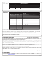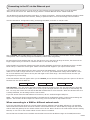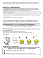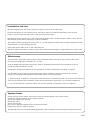
1
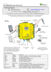
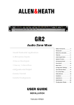
Paxton
05/23/2014
Ins-40080-US Net2 plus control unit - UL
Technical Support
1.800.672.7298
[email protected]
Technical help is available:
Monday - Friday from 02:00 AM - 8:00 PM (EST)
Documentation on all Paxton products can be found on our web site - http://www.paxton-access.com/
For instructions in alternative languages - http://paxton.info/1000
Intruder alarm
integration
Wiring
12V DC power
supply
The Net2 plus ACU has 2 reader ports and 3
output relays, but can control just one door.
The configuration of one control unit per door
greatly simplifies installation and is ultimately
highly cost effective.
Power
Power
DC Only
Relay 1
Buuttttoonn
EExxiitt B
Grreeeenn
G
Orraannggee
O
W
Whhtt//G
Grrnn
I
Clock/D1
PSU
Media Detect
Power
Power
DC Only
0V
0V
Relay 1
N.C.
Relay 2
Outputs
O
N.O..
COM
N.O.
COM
Alarm
12V
End of Line Termination
0V
Server
Server Connected
Connected
OFF
ON
RS485 Network
CAT5 Cable
Cable Coding
CAT5
Coding
Tx
Tx
Rx
Rx
Grreeeenn
G
Orraannggee
O
W
Whhtt//G
Grrnn
0V
10
10
Server
Server Link
Link
100
100
10/100
10/100 Ethernet
Ethernet
Whhtt//O
Orrnngg
W
0V
00-01-02-03-04-05
SSccrreeeenn oorr ssppaarree
ccoorreess ffrroom
m ddaattaa
ccaabbllee
TX
10
100
TCP/IP patch lead
0V
Clock/D1
RS485
CAT5
Media
Detect
0V
Green LED
Exit
0V
Contact
0V
0V
Tamper
PSU
RX
PSU
to next ACU
10/100 Ethernet
For a fail open lock (Maglock), wire 0V to the
"N.C." terminal instead of "N.O."
LED indications
12/24V
Relay 1
Relay 2
Alarm
Exit
Contact
Tamper
PSU
Green LED
123456
LABEL
HERE
Buuttttoonn
EExxiitt B
0V
Red LED
Amber LED
Data/D0
http://paxton.info/107
http://paxton.info/107
IInnppuuttss
Media Detect
12V
12-24V
N.C.
Net2 plus
12V
Tamper
Intruder
Intruder
AlarmAlarm
EXIT 0V2345612
Clock/D1
CCoonnttaacctt
Data/D0
Data/D0
U//TTaam
mppeerr
PPSSU
PSU
Power
Power
DC Only
Relay 1
Outputs
O
Relay 2
Buuttttoonn
EExxiitt B
from previous ACU
0V
EXIT
PSU
0V
Set
Set
Amber LED
R
Reeaaddeerr 22
CCoonnttaacctt
0V
U//TTaam
mppeerr
PPSSU
IInnppuuttss
Exit
Contact
Expansion
Red LED
Green LED
00VV
Green LED
12V
LED
12V
Cautio
on
n:: FFoorr 1122V
VD
DC
C rreeaaddeerrss oonnllyy
Rx
Rx
Normally
N.O closed door contact
COM
(optional)
Reader 1
Tx
Tx
Whhtt//O
Orrnngg
W
10
10
Server
Server Link
Link
100
100
10/100
10/100 Ethernet
Ethernet
RS485 Network
CAT5 Cable
Cable Coding
CAT5
Coding
N.C.
2
AArrm
m
12V
OFF
ON
SSccrreeeenn oorr ssppaarree
ccoorreess ffrroom
m ddaattaa
ccaabbllee
0V
LED
Alarm
End of Line Termination
12V
Tamper
switch
2
LED
(optional)
10/100 Ethernet
Server
Server Connected
Connected
OK
0V
LED
N.C.
N.O.
COM
Clock/D1
Media Detect
PSU
COM
CCOOMM
R
Reeaaddeerr 22
Data/D0
Switchable 120 ohm
resistors
N.O
1
SSennsse
Amber LED
Green LED
COM
Data/D0
1
12V DC
Red LED
123456
LABEL
HERE
00-01-02-03-04-05
LED
PSU
LED
N.C.
NN.O
.O..
12V
2345612
0V
0V
LED
Tamper
Net2 plus
0V
Cautio
on
n:: FFoorr 1122V
VD
DC
C rreeaaddeerrss oonnllyy
Media Detect
N.C.
N.O..
12V - 24V
0V
12V
Media
Detect
0V
RX
Exit button (push to make)
0V
http://paxton.info/107
http://paxton.info/107
Clock/D1
10
100
0V
ARM
Green LED
Data/D0
Reader 1
Net2 plus
0V
0V
Rx
Rx
0V
Contact
SENSE
Intruder
Intruder
AlarmAlarm
Red LED
Amber LED
12V
12-24V
Tx
Tx
Exit
12V DC
Set
RS485 Network
CAT5 Cable
Cable Coding
CAT5
Coding
Green LED
Clock/D1
TX
00VV
AArrm
m
CCOOMM
SSennsse
NN.O
.O..
Set
10/100
10/100 Ethernet
Ethernet
0V
RS485
CAT5
Expansion
10
10
Server
Server Link
Link
100
100
EXIT 0V
I
Media
Detect
12V
12V
0V
LED
0V
Clock/D1
0V
Server
Server Connected
Connected
Orraannggee
O
Data/D0
Media Detect
EXIT
12V DC
LED
COM
Clock/D1
Grreeeenn
G
LED
OFF
ON
Whhtt//O
Orrnngg
W
LED
End of Line Termination
W
Whhtt//G
Grrnn
Reader/keypad
2
(optional)
Alarm
12V
SSccrreeeenn oorr ssppaarree
ccoorreess ffrroom
m ddaattaa
ccaabbllee
12V
N.O
Data/D0
Door Lock
COM
N.O
OK
0V
2
N.C.
N.O.
COM
Media
Detect
GreenN.C.
LED
00-01-02-03-04-05
N.O..
N.C.
Clock/D1
Net2 plus
12V DC
Data/D0
N.O
Amber LED
COM
R
Reeaaddeerr 22
1
123456
LABEL
HERE
IInnppuuttss
N.C.
Red LED
1
LED
0V
0V
COM
CCoonnttaacctt
0V
2345612
U//TTaam
mppeerr
PPSSU
12V - 24V
0V
12V 0V
Cautio
on
n:: FFoorr 1
122V
VD
DC
C rreeaaddeerrss oonnllyy
0V
ARM
COM
SENSE
N.O
N.C.
Media Detect
Ou
utputs
tputs
O
http://paxton.info/107
http://paxton.info/107
12V
12-24V
N.C.
Relay 2
Green LED
Clock/D1
LED
00VV
Net2 plus
Reader 1
Amber LED
Data/D0
LED
Set
Intruder
Intruder
AlarmAlarm
Red LED
12V
AArrm
m
Set
SSennsse
12V
CCOOMM
Reader/keypad
NN.O
.O..
Expansion
(Green)
(Orange)
(Orange)
(Red)
(Orange)
(Orange)
(Orange)
(Orange)
OK
(Green flash)
Termination
(Red)
Rx
(Red)
Tx
(Green)
Server Connected (Green)
Server Link
-
Power LED.
The relay is energised - (NO/COM contacts are closed).
The relay is energised - (NO/COM contacts are closed).
12V Alarm output is active.
The exit button contacts are closed.
The door contacts are closed.
The tamper contacts are closed.
The PSU contacts are closed.
-
The internal software is running.
The on-board resistors are in place across the RS485 data pairs.
The ACU is receiving data (TCP/IP or RS485) - See also FAQ section.
The ACU is responding to data - (TCP/IP or RS485).
The TCP/IP interface is communicating with the PC Net2 server.
Green = 100 Mbit/s : Orange = 10 Mbit/s (TCP/IP speed).
PAGE 1
Overview
A Net2 plus can connect to the Net2 PC using either an un-shielded RJ45 patch cable or an RS485 data line. This
greatly increases the number of installation options available to the installer.
One Net2 plus can also be used as the TCP/IP interface for an RS485 daisy chain of Net2 plus and Net2 classic units.
When used with a TCP/IP connection, it must first be detected using the Net2 Server Configuration Utility as defined
later in this instruction.
When used with an RS485 data line, on-board termination resistors can be put in circuit with a simple slide switch.
Ensure that units installed in the middle of the data line have this switch turned OFF.
A dedicated Intruder Alarm connection is provided.
Site Layout Examples
Power
Relay 1
+12v
0v
N.C.
N.O.
Com
N.C.
N.O.
Com
Alarm Output
0v
Contact
0v
Inputs
Orange
Relay 2
CAUTION: for 12v d.c. readers only. For
correct connection of old 5v readers, refer to
instructions.
o er
Relay 1
Outputs
Relay 2
utton
Exit
Inputs
Contact
/ amper
o er
Relay 1
Outputs
Relay 2
utton
Exit
Inputs
Contact
White/Orange
Exit
0v
Tamper
PSU
5v
12v
Tx
OK
Rx
Exit
PSU
t/Grn
Green
t/Orn
Tamper
Green
4
Relay 2
/ amper
o er
Relay 1
Outputs
Relay 2
utton
Exit
Inputs
Contact
White/Green
2
3
Relay 1
/ amper
o er
Relay 1
Outputs
Relay 2
utton
Exit
Inputs
Contact
o er
Relay 1
Outputs
Relay 2
utton
Exit
Inputs
1
4
Contact
24898 00000
0V
Contact
/ amper
3
Screen or spare cores
from network cable
0V
amper
Red
Serial number
241821
Orange
0V
Brown
Yellow
Exit
Contact
Orange
Brown
Green LED
Reader 2
Network
Rx
CAT5 cable coding
OFF
Net ork
Cable Codin
x
Keypad 1
Line ermination
R
CA
Oran e
t/Grn
Green
t/Orn
10
100
ernet
Reader 1
er er Connected
er er Link
10/100 Et
Mauve
Test ID: 012345678901
0V
Blue
Black/White
z-1440
Media Detect
Brown
End o
ON
Clock/D1
0V
Blue
Green LED
Data/D0
0V
amper
Green
Yellow
Yellow
Amber LED
0V
Brown
Orange
Mauve
Red LED
Exit
Contact
N.C.
N.O.
COM
Green
Green LED
Keypad 2
Red 12v dc
N.O.
COM
Alarm
Yellow
Rx
0V
12V
Black/White
OFF
Net ork
Cable Codin
x
Orange
Line ermination
R
CA
Oran e
t/Grn
Green
10
100
ernet
12V
N.C.
LACE ERIAL
N M ER
LA EL ERE
creen or spare
cores rom data
cable
er er Connected
er er Link
10/100 Et
Intruder Alarm
Net2 plus
0V
12V
Reader 2
0V
et
Red LED
Amber LED
Green LED
Data/D0
Clock/D1
Media Detect
Caution: For 12V DC readers only
Media Detect
TCP/IP
LAN
End o
ON
Clock/D1
0V
N.C.
N.O.
COM
Reader 1
Data/D0
0V
amper
ense
Green LED
0V
N.O.
COM
Alarm
Net2 classic
0V
Amber LED
Exit
Contact
COM
Red LED
Green LED
12V
0V
12V
creen or spare
cores rom data
cable
Rx
N.O.
OFF
Net ork
Cable Codin
x
12V
N.C.
LACE ERIAL
N M ER
LA EL ERE
Arm
Line ermination
R
CA
t/Orn
10
100
ernet
0V
12V
Reader 2
er er Connected
er er Link
10/100 Et
Intruder Alarm
Net2 plus
Clock/D1
Media Detect
Caution: For 12V DC readers only
0V
Expansion
et
Reader 1
Media Detect
12V
Red LED
Amber LED
Green LED
Data/D0
ense
End o
ON
Clock/D1
0V
2
Net2 plus
0V
Data/D0
0V
amper
N.C.
N.O.
COM
COM
Green LED
0V
N.O.
COM
Alarm
Expansion
N.O.
Amber LED
Exit
Contact
0V
12V
Oran e
TCP/IP
LAN
Red LED
Green LED
12V
N.C.
LACE ERIAL
N M ER
LA EL ERE
creen or spare
cores rom data
cable
t/Grn
Green
t/Orn
ernet
Rx
Reader 2
OFF
Net ork
Cable Codin
x
Intruder Alarm
Net2 plus
0V
12V
Caution: For 12V DC readers only
Line ermination
R
CA
Oran e
t/Grn
Green
t/Orn
10/100 Et
10
100
et
Red LED
Amber LED
Green LED
Data/D0
Clock/D1
Media Detect
Net2 plus
Arm
N.C.
N.O.
COM
Reader 1
End o
er er Connected
er er Link
ense
N.O.
COM
Alarm
creen or spare
cores rom data
cable
0V
0V
Media Detect
12V
0V
12V
ON
Clock/D1
0V
COM
Data/D0
0V
amper
Reader 2
Green LED
0V
N.O.
Amber LED
Exit
12V
N.C.
LACE ERIAL
N M ER
LA EL ERE
Arm
0V
Red LED
Green LED
Contact
TCP/IP
LAN
0V
Caution: For 12V DC readers only
Rx
Oran e
ernet
creen or spare
cores rom data
cable
10/100 Et
Net ork
Cable Codin
x
Intruder Alarm
Net2 plus
Reader 1
OFF
R
CA
ense
Reader 2
Caution: For 12V DC readers only
Line ermination
ON
10
100
et
Red LED
Amber LED
Green LED
Data/D0
Clock/D1
Media Detect
12V
12V
End o
er er Connected
er er Link
COM
Reader 1
N.C.
N.O.
COM
Clock/D1
N.O.
N.O.
COM
Alarm
Media Detect
0V
12V
0V
Net2 plus
Expansion
12V
N.C.
LACE ERIAL
N M ER
LA EL ERE
Arm
ense
12V
Red LED
Amber LED
Green LED
0V
Intruder Alarm
Net2 plus
0V
Net2 plus
Expansion
et
Clock/D1
Media Detect
Data/D0
COM
N.O.
12V
Red LED
Amber LED
Green LED
Data/D0
Arm
1
Expansion
/ amper
Net2 plus
RS485 dataline
TCP/IP
LAN
Here are two typical site layouts.
1 - The Net2 plus ACU's can be individually connected to the Net2 PC via the site LAN network.
2 - The Net2 plus ACU can be used as the TCP/IP converter for a line of Net2 plus and Net2 classic ACU's.
The TCP/IP interface allows an RS485 data line to be controlled by the Net2 Server running across a LAN network.
An RS485 data line has a 1000 yds maximum. This distance can be increased with the use of Paxton high speed
repeaters or by using shorter independant data lines using multiple LAN connections controlled from the same PC.
The ACU shall be installed within the protected premises as both the power and lock wiring is present at the PCB.
A Tamper alarm input is provided on the PCB - See Input/Output Wiring
The ACU's will continue to operate in a 'standalone' mode if the PC is shut down or the dataline is disconnected.
Any Events that occur during this period are stored in the ACU and the PC is updated when it comes back on line.
The PC must be running for any 'server based' functions to operate. (Antipassback, Time and Attendance, etc).
TCP/IP and RS485 LED indication
The Net2 plus performs two functions. It is an access control unit and also a TCP/IP RS485 converter. Information
can pass across the PCB between the TCP/IP and RS485 data port but is not relevant to this ACU
- Server Connected LED (Steady Green)
This LED shows that the TCP/IP interface is active and receiving data from the Net2 PC server. This includes all data
for other ACU's that may be linked via the RS485 data port.
- Rx and Tx LED's
These LED's show the activity for this ACU only. This is same indication as seen on a Net2 classic ACU.
It is not dependant on the source (TCP/IP or RS485). The Rx LED will flash for all data being received and the Tx
LED will only flash when this unit responds to its own address.
PAGE 2
Cable type
Cable specification
Use
Max length
RS485 Data Line
1000 yds
Reader / Keypad
500 feet
Input / Output
100 yds
Type
2 x twisted pairs - Belden 8723 or Cat5 equivalent
8 core, shielded - Beldon 9538, Alpha 1298C (22AWG) or equivalent
2 conductor - Alpha 1172C (22AWG) or equivalent
Mounting
Parts kit
Part Number
Qty
Fitting Kit fk1-108
1
Ferrite tube
1
Grommet, 22mm hole
3
Wall plugs
3
Pozi round woodscrew - zinc
1
Pozi panhead lid screw
1
Rubber washer
1
Cable gland
1
Cable gland lock nut
4
Cable clip
10
Cable tie
Fitting Kit fk1-039
Description
1
1N4001 diode
4
120 ohm Resistor 1/4W
2
Cable tie
The ACU is supported on mounting posts located at the corners.
If the unit is supplied in a plastic housing, it should be fixed to the surface with suitable fasteners. Four screws and
wall plugs are provided for this in the parts kit along with cable ties and two smaller screws for the lid.
Mount the four corner f/f mounting posts to the plate with four of the machine screws and then secure the circuit
board to their tops using the remaining four screws.
Control unit installation
This unit is for Indoor use only
The ACU shall be installed within the protected premises as both the power and lock wiring is present at the PCB.
Tamper alarm input is provided on the PCB - See Input/Output Wiring
A
Where the ACU is being installed within a plastic enclosure, the hub must be connected to the conduit before it is
connected to the plastic enclose. This is to eliminate the potential of any excessive torque loading being applied to the
plastic enclosure during installation.
This housing should be fixed to the surface with suitable fasteners; screws and wall plugs are provided for this in the
fitting kit. Also provided are cable ties to secure the cabling and a smaller securing screw for the lid.
Wire the components to the Access Control Unit (ACU) as shown on the first page.
Press the exit button or in the absence of an exit button, short the 0V and exit terminals together. The configured lock
output LED will come on and the lock should release.
The unit will continue to operate in a 'standalone' mode if the PC is shut down. Any Events that occur during this period
are stored in the unit and the PC is updated when it comes back on line.
PC installation
The current specification for compatible PC hardware, network and operating systems is available on our website at the
following link: http://paxton.info/720
PAGE 3
Connecting to the PC via the Ethernet port
If the TCP/IP data connection is longer than 25 ft the following surge protection device must be installed
within 3 ft of the control unit. Data line surge protector. Emerson Network Power: Model LCDP-060.
The IP address should be assigned a fixed value, or a DHCP reservation. Unreserved IP addresses issued by DHCP
servers are not guaranteed to be constant, leading to potential failure of PC to Net2 bridge communications.
Run the Net2 Server Configuration Utility (Start/Programs/Net2) and Click on TCP/IP nodes.
Click on;Detect and the MAC address of the device(s) will appear in the table. You must then use the "IP address
configuration" tab to manually assign the IP address, subnet mask and gateway.
Be aware that if the IP address that you give the device is not in the same IP range as the PC, the device will no
longer respond until you connect to it with a PC that is in the same IP range.
Some firewall/virus protection software and other wireless hardware can block the IP detection process. Disable
these and try to detect the device again. Please contact Technical Support if you require further advice.
If you detect the MAC address but the device now shows 'Not Responding', you must check the IP address, to
make sure it is still in range with the PC or network. If it is not, you should either change the IP address of the
PC or the IP address of the device so they are both again in the same range. Our Technical team can talk you
through this if you need help.
If the MAC address does not appear when you click;Detect, ensure that the following ports are open on all devices
between this unit and the Net2 PC:69
UDP
10001
TCP
30718
UDP
TCP/IP Reset - The unit can be returned to DHCP settings by powering down the unit and linking the 'Red LED'
and 'Media Detect' terminals on reader port 2. Power up the unit again and the unit will beep to acknowledge the
link. You may now remove the link and the OK LED will flash fast for a few seconds. When the OK LED returns to
a steady heartbeat, the IP settings will be reset to DHCP.
If you still cannot detect the MAC address of the device, call our Technical Support Help line.
NOTE: The device will 'beep' when detected by the Net2 Server Configuration Utility or when new IP settings are
applied. The sounder will also respond to a direct 'Ping' over the network to help locate the unit.
When connecting to a WAN or different subnet mask
If you are connecting this device to a remote subnet which is different from the Net2 software PC, the standard
detect mechanism cannot work across the network routers between them. The IP address, along with the correct
subnet mask and gateway for the remote subnet have to be set. Either do this on the local subnet with the existing
Net2 PC, or use a PC on the remote subnet once the device is installed.
The PC that has the Net2 server installed must be able to access the IP address range on the WAN/remote site.
PAGE 4
This may require the routers and gateways to be configured between the networks. Again, this would be done by
the Network administrator of that site. Make sure the ports listed above are open on all intermediate routers.
Once installed, create a record with the;Add button (if none was created during initial set up) and you should then
be able to detect its MAC by entering the IP address in the Configuration screen Ping box.
Naming TCP/IP Ethernet interfaces
The rename button can be used to give an interface a meaningful name in the system. This can be especially
useful when more than one interface is used, as the name will appear in the doors screen within Net2 showing
which ACUs are connected to which dataline, helping in any future fault finding process.
TCP/IP Loopback test
The following test should be run if there are problems setting up the IP configuration of the interface. This test
sends data to the device and checks this against the data it receives back. This confirms that the network pathing
is working correctly.
The Net2 server program must be shut down during this test.
Remove any wires from the RS485 data line connector and create a hardwired data loop as follows. Connect the
Orange to White/Green and Green to White/Orange. To run the test, click the Loopback button in the advanced
section of the Server Config Utility/TCP/IP Nodes. If the test fails, connect the unit directly to the PC with a
network patch cable and test it again. Should this still fail, please call Technical Support for further advice.
Connecting to the PC or other ACU's via the RS485 data connection
90% of installation faults are caused by wiring errors on the RS485 data line.
Special attention to this area can save time and effort.
END OF LINE TERMINATION - 120 ohm resistors must be linked across each data pair at the beginning AND end of
the line. This can be done on many units with a switch or jumpers. If not, resistors are provided with the converter.
Reader & Data Cable Screens
- Data cable screens and spare cores MUST be connected throughout.
- Reader and keypad screens where provided, should be connected to the Black 0V terminal.
The data line must be wired in a single daisy chain. The data connection to the PC may be located at any position
along the data line.
Reader
Net2
Server
Control unit
RS485 data line resistance check
Power down all TCP/IP, USB and RS232 converters (individual and Net2 plus).
Check the resistance across each data pair is 60-80 ohms.
Check that there are no data line to screen shorts.
Check the screen of the data cable is continuous - this provides the 0V DC system reference.
PAGE 5
Installation and test
Wire the components to the Access Control Unit (ACU) as shown on the first page.
Press the exit button or in the absence of an exit button short the 0V and exit terminals to test the relay
function. The lock Relay LED will come on and the lock should release.
Each time the unit is powered on, it will run an internal health check. During this phase (about 5 secs) the OK
LED will flash quickly before changing to a slower heartbeat.
The reader's default indication has all the LED's on. Access granted is denoted with a single flashing Green LED.
Access Denied is a single flashing Red LED.
Ensure that all the LED's are lit on the reader/keypad.
Test each reader by presenting a token and the unit should beep and display a single flashing red or green LED.
Maintenance
The Net2 ACU is designed to take input from Clock and Data readers through its two (In/Out) reader ports.
It can also be configured for Wiegand (26 / 50 bits).
It has an RS485 communications port that is used for uploading firmware and user information as well as
providing Event information to the PC.
Following the completed installation of this equipment, no further maintenance or testing is required.
It is advisable to ensure that any third party backup power supplies or recovery procedures are checked
regularly to ensure that the operation of the Paxton system is not compromised.
1 - Short circuiting, mutilation or incineration of the cells must be avoided to prevent one or more of the following
occurrences; Release of toxic materials, release of hydrogen and/or oxygen gas, rise in surface temperature.
2 - If a cell has leaked or vented the control unit must be replaced. The battery is not to be replaced.
System checks
Present a token at each reader. An event for each read should appear in the Events screen.
Change the default password for the System Engineer.
Set up other operators if required.
Set up time zones.
Set up access levels.
Users can be added & assigned to the required access level.
Departments can be created if required.
The Net2 CD can assist here with detailed application notes for setting up users and general system operation.
PAGE 6
INPUT / OUTPUT WIRING
Exit button
Where fitted, a 'push to make' button is required.
(See Specification table for ratings)
The Exit LED will be ON when the switch is closed. Button Pushed.
When the Exit terminal is shorted to 0V, the Exit LED will illuminate and the ACU will operate Relay 1.
The reader/exit button Green LED will flash during this period. More than one exit button can be wired in
parallel. Relay 1 will remain transfered while the short to 0V remains.
Door Contact
A NO switch may be fitted so that it is held closed while
the door is shut.
The Contact LED will be ON when the switch is closed.
- Door Closed.
When connected, Net2 will check the door position during
access activity and will raise an Alarm in the event of a
'Door Forced' or 'Door left open' condition.
Tamper switch
The ACU supplied in a plastic housing has a 'NO' tamper
switch fitted and pre-wired into the circuit board.
The Tamper LED will be ON when the switch is closed.
Net2 will monitor the switch position and will raise an
Alarm in the event of a 'Tamper' condition.
Connect to a UL listed burglar alarm unit for supervision.
PSU monitoring
The PSU LED will be ON when the NO Relay contacts are
closed. - Power OK.
The Net2 software will monitor the relay contacts
and will raise an Alarm in the event of a 'Power Fail'
condition.
Door Bell - Relay 2
Pressing the bell button on the keypad will result in
Relay 2 being energized for 1 second. A bell sounder
can be controlled by wiring one of the bell feeds
across COM / NO on the relay.
See Specification table for Output Ratings
PAGE 7
Alarm sounder
This local alarm has a transistor 'open drain' output, (not a dry
contact relay) and will switch 1A at 12V DC for a bell, light etc.
This local output can be turned on or off for each type of alarm
and can be configured to sound continuously or intermittently to
distinguish between different alarm types.
Lock Wiring - Relay output
12V DC power supply
Lock power supply
Door lock
Fail closed
Fail open
Lock with an independent supply
This is a ONE door controller using a dry contact relay.
The lock is wired across 12V and COM. A link (0V to NO or NC) is required, depending on lock type (Fail Closed /
Open). Fit the supplied diode across 12V and COM (Silver end to 12V ) to protect the relay contacts.
The dry relay contacts can be used to switch the power from an independent lock power supply. Wire the 0V to
NC or NO and the lock to COM; the +VCC supply is wired directly to the lock.
Panic hardware
A break glass should be fitted, in conjunction with a fail open release to
ensure a reliable egress method in the event of an emergency. This is
fitted on the 12V supply wire to the lock and drops the power ensuring
that the lock opens.
Break Glass fitted
The diagram shows how to include the break glass in the Net2 lock wiring
circuit.
Fire Door Interface
A fire alarm system must be used to release all fire doors. External
relay contacts are held closed by the fire alarm's interface and will be
dropped during an alarm condition. The system is fail safe as the door
will release even if the cable burns through.
External Fire Door relay fitted
PAGE 8
Software configuration
Door name: Name the Door.
Door open time: Set the door open time.
Unlock the Door during: Holds the door unlocked during this
timezone. - Set to 'At No Time' for normal user operation.
Reader 1: Settings for Reader 1 and Keypad 1 on the ACU.
Reader 2: Settings for Reader 2 and Keypad 2 on the ACU.
Alarm: Contains settings for the different types of alarm.
Codes: Valid codes can be viewed, added and removed.
(Can only be viewed when a keypad is active).
Events: Shows the events for the control unit selected.
Name: Each reader can be named individually if required.
Reader type: Set the reader type, if applicable.
Keypad type: Set the keypad type, if applicable.
Token data format: Select the type of cards being used
on the system. (New formats can be created).
Reader operating mode: Set the operating mode.
Timed operating modes: A different operating
mode can be configured within a time window.
Reader action: Set the action required
when access is granted.
UL compatable readers
Part
Type
Part
Type
371-110-US
TOUCHLOCK K75 keypad
373-110-US
PROXIMITY P75 reader
371-120-US
TOUCHLOCK K75 keypad, screw connector
373-120-US
PROXIMITY P75 reader, screw connector
372-110-US
TOUCHLOCK K75 stainless steel keypad
353-110-US
PROXIMITY P50 reader
372-120-US
TOUCHLOCK K75 stainless steel, screw connector
390-747-US
PROXIMITY metal reader
375-110-US
PROXIMITY KP75 keypad
390-727-US
PROXIMITY metal reader, chrome
375-120-US
PROXIMITY KP75 keypad, screw connector
390-737-US
PROXIMITY metal reader, brass
390-135-US
PROXIMITY panel mount reader
Intruder alarm integration
A dedicated port for input and output signals is provided when integrating a Net2 plus ACU with an alarm system.
Please see AN1035 - Integrating Net2 with an intruder alarm system < http://paxton.info/91 > or call Technical
Support for further information.
Arm
- Arm confirmation Push Button - Wire across 0V and Arm.
Sense - Wire a voltage free loop across 0V and Sense to monitor the alarms current status.
Set
- Wire a voltage free loop across COM and N.O. or N.C. to provide a set signal for the alarm.
PAGE 9
Technical Help
1 - RS485 Data line resistance check - ACU not responding or fails to be detected.
QFirst power down any data line converters and disconnect any ACU's that do not have a flashing OK LED. Using a
QMultimeter, measure the resistance across the White/Green and Green pair at one end of the network.
QA resistance of between 60 and 80 ohms is required. Repeat the test for the White/Orange and Orange pair.
QThis is vital for a stable and trouble free installation.
2 - ACU Reset - No OK LED flashing.
QThe ACU has no factory reset condition as it does not contain any fixed settings. The unit does have an operating
Qprogram (firmware) that controls its functions and can be confirmed as running by means of the flashing OK LED.
Q- If the OK LED is flashing steadily, then there should be no reason to reset the unit.
Q- If the OK LED is not flashing, you need to clear the unit so that it can receive a firmware download from the PC.
Q Any other ACU's without OK LED's must be taken off the line or powered down.
Q1.
Q2.
Q3.
Q4.
Q5.
Q6.
Q
Q
Q
Q
Q
Stop Net2 Server (Net2 server icon - Bottom right of screen - Right mouse click, Select Stop the Net2 Server).
Power down the Net2 ACU.
Insert a link wire between the 'Amber LED' and 'Media Detect' terminals on reader 2 port.
Power up the ACU. - The OK LED flashes very quickly.
With the unit still powered, remove the link.
Go to the PC and Start the Net2 Server and go into the Doors screen. Click on the Detect button. This
should look for the ACU and then download its firmware (This may take up to 5 minutes). - The OK LED
should now be flashing with a steady heartbeat. This procedure must only be done for one ACU at a time.
NOTE: If this unit is using the TCP/IP interface, any fixed IP settings will be retained.
If the unit is in DHCP mode it will need to be detected at each stage using the Server Config Utility as a new
address may be issued by the IP server, each time the PCB resets.
3 - Can we use a DHCP IP address?
QThe Ethernet interface does support DHCP, but for more reliable communication, a static IP address must be
Qreserved for the unit. This is because some servers issue different DHCP addresses each time they are restarted
Qand this requires the Net2 interface to be manually set up again - a time consuming process.
4 - TCP/IP - Direct PC connection.
QConnect the network interface directly to the LAN port of the PC. Without the presence of a DHCP server the unit
Qwill default to an IP address in the range 169.254.X.X.
QCheck the IP address of the network card of your PC by typing IPCONFIG at the command prompt. Detect the
QTCP/IP interface through the Net2 Configuration Utility and change the IP address of the interface to an address
Qsimilar to that of your machine. For example, if the IP address of the PC is 192.168.10.7, change the IP address
Qof the TCP/IP interface to 192.168.10.8. Once the IP address of the interface has been changed into the range of
Qthe PC then Net2 will be able to communicate with it.
QNOTE: Do not change the IP address of your PC to 169.254.x.x, this will not allow the IP address of the TCP/IP
Qinterface to be fixed correctly.
5 - Cannot detect ACU via a TCP/IP interface.
Q1.
Q
Q2.
Q3.
Ensure the TCP/IP interface has been detected in the Net2 Configuration Utility, and responds when PINGed
from the utility. A static IP address must be used for the interface.
If the interface is responding, try a loopback test. (see Loopback section)
The Net2 data line should be checked for resistance readings.
6 - Readers/Keypads not working.
QQQQ
QQQQ
Software settings - Confirm that the settings of the reader or keypad are correct.
Connections - Check the wiring and integrity of the connectors. - If possible, test this reader on the other port.
Cable - Belden 9540 or 9538 should be used to extend the reader cable. Twisted pair alarm cable
should not be used. To confirm that a cable extension is not at fault, wire the reader direct into the reader port.
Supply voltage - Confirm that the voltage is within specification. (see table)
User token - Confirm that the user token used for testing is OK by presenting it to a known working reader.
Interference - Confirm whether the reader works when tested 'in hand' and not mounted on the wall. Ensure
that readers are not mounted back to back or there is no interference from other local RF devices.
PAGE 10
Product compliance and limitations
To comply as a UL listed installation, the following conditions must apply:The power must be provided via a separate DC supply, a UL Listed Access Control (or Burglar Alarm) Class
2, Power-Limited, power source capable of 4 hours standby must be employed. This is wired into the 0V
and 12/24V terminals and the cable secured with the cable ties provided.
Wiring methods shall be in accordance with the National Electrical Code (ANSI/NFPA70), local codes, and the
authorities having jurisdiction.
Software features and functions have not been evaluated by UL.
Server based functions (Antipassback, Time and Attendance, etc) have not been evaluated by UL and cannot be used
for UL 294 installations.
The use of Wiegand readers and the configuration software has not been evaluated by 'UL'
Wiring: - Where an equivalent cable / wire is used it must be ' UL Listed '
All interconnecting devices must be UL Listed.
Exit buttons - A UL listed 'push to make' button must be used.
Door contact - A UL listed 'Normaly Open' (N.O.) switch must be used.
Tamper alarm - Connect to a UL listed burglar alarm unit for supervision.
Alarm sounder - Connections to this alarm output have not been evaluated by UL for burglar alarm use.
Break glass- A UL listed break glass must be used.
Fire door interface - This feature has not been evaluated by 'UL' and must not be used in UL-294 installations.
Intruder alarm integration - This feature has not been evaluated by 'UL' and must not be used in UL-294 installations.
For CAN/ULC-S319 installations, terminals, leads and wiring methods must comply with CSA, C22.1, Canadian
electrical code, Part 1, safety standards for electrical installations.
The use of any add-on, expansion, memory or other module manufactured or supplied by the manufacturer's
representative will invalidate the CAN/ULC-S319 certification.
This device complies with Industry Canada licence-exempt RSS standard(s). Operation is subject to the following two
conditions: (1) this device may not cause interference, and (2) this device must accept any interference, including
interference that may cause undesired operation of the device.
FCC Compliance
Class B digital devices.
This equipment has been tested and found to comply with the limits for a Class B digital device, pursuant to Part 15 of
the FCC Rules. These limits are designed to provide reasonable protection against harmful interference in a residential
installation. This equipment generates, uses and can radiate radio frequency energy and, if not installed and used
in accordance with the instructions, may cause harmful interference to radio communications. However, there is no
guarantee that interference will not occur in a particular installation. If this equipment does cause harmful interference
to radio or television reception, which can be determined by turning the equipment off and on, the user is encouraged
to try to correct the interference by one or more of the following measures:
-- Reorient or relocate the receiving antenna.
-- Increase the separation between the equipment and receiver.
-- Connect the equipment into an outlet on a circuit different from that to which the receiver is connected.
-- Consult the dealer or an experienced radio/TV technician for help.
PAGE 11
Options
Sales Code
Description
682-493-US
Net2 plus access control unit
682-528-US
Net2 plus ACU in plastic housing
Specifications
Electrical
Min
Max
Voltage
12V DC
24V DC (+20%)
PCB Current (depending on activity)
200 mA
3A
24V DC (+20%)
Relay switchable voltage
4A
Relay switchable current
Alarm output voltage
12V DC
Alarm output current
1A
500 mA
Combined reader port output current
Reader port voltage
11.4V DC
12V DC
Exit button voltage
11.8V DC
12V DC
20 mA
Exit button current
Environment
Operating temperature - Battery limits
Min
Max
0 °C (32 °F)
55 °C (131 °F)
Humidity
85% - Relative humidity
Waterproof
No
Communication
Min
Max
Ethernet network speed
10 Mbits/sec
100 Mbits/sec
Ethernet bandwidth requirement
200 kbits/sec
DHCP support (fixed IP recommended)
Yes
RS485 network speed
Features
115.2 kbits/sec
Min
Max
Number of Cards
50,000
Net2 v4.16
Number of PIN's
50,000
Net2 v4.16
Access Levels
250
Time Zones
64
Maximum door open time
1 sec
Number of Codes
999,999 sec
50
Doors per ACU
1
Reader ports per ACU
2
Readers per port
2
Keypads per port
2
ACU per dataline
200
Datalines per PC
200
Data retention after total power loss
30 days
Events stored in ACU with no server connection
Dimensions
Control Unit
Net2 v4.21
2,728
Width
Height
Depth
4 1/2 inch
5 inch
1 inch
This product is not suitable for retail sale. All warranties are invalid if this product is not installed by a trained technician.
PAGE 12