1
8E - 4
INSTRUMENT PANEL SYSTEMS
DN
DESCRIPTION AND OPERATION (Continued)
CENTRAL TIMER MODULE
DESCRIPTION
Two versions of the Central Timer Module (CTM)
are available on this vehicle, a base version and a
high-line version. The base version of the CTM is
used on base models of the vehicle. The base version
of the CTM combines the functions of a chime/buzzer
module, an intermittent wipe module, and an ignition lamp time delay relay in a single unit. The base
CTM also uses inputs from the door ajar switches,
the headlamp switch and the key-in ignition switch
to control the output to the dome lamp circuits,
which allows the base CTM to provide load shedding
to help protect the battery from becoming discharged.
The high-line version of the CTM is used on highline vehicles. The high-line CTM provides all of the
functions of the base version CTM, but also is used to
control and integrate many of the additional electronic functions and features included on the highline models. The high-line version of the CTM
contains a central processing unit and interfaces with
other modules in the vehicle on the Chrysler Collision Detection (CCD) data bus network.
The CCD data bus network allows the sharing of
sensor information. This helps to reduce wire harness complexity, reduce internal controller hardware,
and reduce component sensor current loads. At the
same time, this system provides increased reliability,
enhanced diagnostics, and allows the addition of
many new feature capabilities.
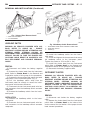
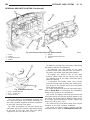
Both versions of the CTM are mounted under the
passenger side end of the instrument panel, outboard
of the instrument panel glove box opening. For diagnosis of the base version of the CTM, refer to Central Timer Module in the Diagnosis and Testing
section of Group 8U - Chime/Buzzer Warning Systems. For diagnosis of the high-line version of the
CTM or the CCD data bus, the use of a DRB scan
tool and the proper Diagnostic Procedures manual
are recommended. The CTM cannot be repaired and,
if faulty or damaged, it must be replaced.
OPERATION
Some of the functions and features that the CTM
supports or controls include:
• Chimes for the following conditions:
• Headlamps on with ignition off and driver door
open warning
• Key in ignition with ignition off and driver door
open warning
• ABS lamp warning (if the vehicle is so equipped)
• Airbag lamp warning
• Check gauges lamp warning
• Door ajar lamp warning
• Low fuel lamp warning
• Low washer fluid lamp warning
• Seat belt reminder lamp warning
• Transmission oil temperature lamp warning
(automatic transmission)
• Central locking
• Courtesy lamp defeat
• Courtesy lamp time-out (high-line only)
• Intermittent wipe control
• Enhanced accident response (high-line only)
• Horn chirp upon door lock with RKE (customer
programmable) (high-line only)
• Illuminated entry (high-line only)
• Power door lock control (high-line only)
• Power lock inhibit (high-line only)
• Remote Keyless Entry (RKE) (high-line only)
• Remote radio switches (high-line only)
• Rolling door locks (customer programmable)
(high-line only)
• Speed sensitive intermittent wipe (high-line
only)
• Vehicle Theft Security System (VTSS) (high-line
only) (if the vehicle is so equipped)
• Wipe after wash (high-line only).
More information on the operation of these CTM
features and functions can be found in the group that
covers the system to which that feature or function
applies.
INSTRUMENT PANEL CIGAR LIGHTER
DESCRIPTION
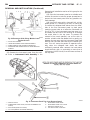
A cigar lighter is standard equipment on this
model. The cigar lighter is installed in the instrument panel lower bezel, which is located near the
center of the instrument panel, below the radio. The
cigar lighter base is secured by a snap fit within the
instrument panel lower bezel.
The cigar lighter knob and heating element unit,
and the cigar lighter receptacle unit are available for
service. These components cannot be repaired and, if
faulty or damaged, they must be replaced.
OPERATION
The cigar lighter consists of two major components:
a knob and heating element unit, and the cigar
lighter base or receptacle shell. The receptacle shell
is connected to ground, and an insulated contact in
the bottom of the shell is connected to battery current. The cigar lighter receives battery voltage from a
fuse in the junction block only when the ignition
switch is in the Accessory or On positions.
The knob and heating element are encased within
a spring-loaded housing, which also features a sliding
protective heat shield. When the knob and heating
element are inserted in the receptacle shell, the heating element resistor coil is grounded through its