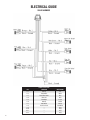
1
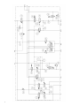
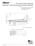
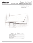
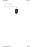
ADVANTAGE + SD
Service Manual - Rev 1
TABLE OF CONTENTS
Hydraulics Service Guide.......................................................................................................................... 3
Specifications............................................................................................................................................ 4
Port Designations...................................................................................................................................... 5
Cartridge Designations, Functions and Part Numbers...........................................................................6-7
Schematic.................................................................................................................................................. 8
Explanation of Pressures........................................................................................................................... 9
Solenoid Shift Sequence........................................................................................................................... 9
Explanation of Unloading Circuit............................................................................................................. 10
Explanation of Spreader Circuit............................................................................................................... 11
Explanation of Plow Circuit...................................................................................................................... 12
Explanation of Plow Down Circuit............................................................................................................ 13
Explanation of Hoist Circuit..................................................................................................................... 13
Explanation of Hoist Down Circuit........................................................................................................... 14
Configuring System from Open to Closed Center................................................................................... 15
Installation of Plow Pressure Release Manifold...................................................................................... 16
Electrical Guide Intro............................................................................................................................... 17
Electrical Wiring Assignments................................................................................................................. 17
Electrical Block Diagram.......................................................................................................................... 18
Electrical Joystick Harness...................................................................................................................... 19
Electrical Slave Harness.......................................................................................................................... 20
Electrical Master/Slave Harness.............................................................................................................. 21
Electrical Controller Errors..................................................................................................................22-23
Glossary of Terms.................................................................................................................................... 24
System Troubleshooting.....................................................................................................................25-27
Controller Panel Errors............................................................................................................................ 27
3
HYDRAULIC SPECIFICATIONS
HYDRAULIC PRESSURE SETTINGS
FUNCTION
Main Relief
Boost
Spreader
Plow Up
Plow Down
Hoist Up
Hoist Down
DESIGNATION
TS3
RV1
RV3
RV5
TS2
RV4
TS1
FUNCTION
Inlet Flow
Plow Up
Plow Down
Plow Angle
Hoist Up
Hoist Down
Spinner
Auger
4
PSI*
2000
200
1600
1300
600
2300
600
MAX FLOW RATES**
40 GPM
15 GPM
15 GPM
06 GPM
14 GPM
14 GPM
15 GPM
15 GPM
RANGE - PSI
1500 - 3600
0 - 500
300 - 3500
300 - 3600
0 - 1700
300 - 3600
0 - 3000
ADJUSTED
Electically
Mechanically
Mechanically
Mechanically
Electically
Mechanically
Electically
DIFFERENTIAL PSI
200
200
200
200
200
200
200
200
HYDRAULIC PORT DESIGNATIONS
T2
HA
PLA
B
P
S
A
PAB
PAA
PLB
HB
T
DESIGNATION
P
T
T2
A
B
S
PLA
PLB
FUNCTION
Pump
Tank
Tank 2
Auger
Auger reverse/Spreader Return
Spinner
Plow Up
Plow Down
SIZE (SAE)
16
16
10
10
10
10
08
08
PGP
DESIGNATION
HA
HB
PAA
PAB
PGP
PT1
PT2
PT3
PT1
FUNCTION
Hoist Raise
Hoist Lower
Angle Left
Angle Right
Pump Gauge Port
Pump Pressure Transducer
Load Sense Pressure Transducer
Plow Raise Pressure Transducer
SIZE (SAE)
08
08
08
08
04
04 Modified
04 Modified
04
5
HYDRAULIC
CARTRIDGE DESIGNATIONS, FUNCTIONS, AND PART NUMBERS
TS3
RV1
FR1
RV3
CV6
RV4
CV7
SP5
RV5
SP6
CV1
EV1
RV6
RV2
SP7
SP3
EP4
SP2
SP4
EP3 EP2
TS1
SP1
EP1
TS2
CV3
CB2
CV11
6
CV10
CV8
CV9
CV2
HYDRAULIC
CARTRIDGE DESIGNATIONS, FUNCTIONS, AND PART NUMBERS
DESIG
PART NUMBER
FUNCTION
LOC.
DESIG
PART NUMBER
FUNCTION
LOC.
RV1
NXRV0820A0NC05/02
RV2
NXRV0822A0N26
Boost Pressure
Top
Plow Angle Left Relief
Front
SP2
SP3
SP4
SP5
SP6
SP7
ORF1
ORF2
ORF3
ORF4
EP1
EP2
EP3
EP4
FR1
EV1
CL1
CL2
BLK
Not Shown
NXSP1020AM0N00
NXSP1020M0N00
NXSP08200N00
NXSP0820M0N00
NXSP08200N00
NXSP1057C0N00
NX6101025
NX6101025
NX6101025
NX6101025
NXEP08350N10
NXEP10S350N10
NXEP10S350N10
NXEP10S350N10
NXFR0820F0N/0.20
NXEV12S340N010
COIL 4303612
COIL 4303712
BLOCK 7620110
NX6108080
Auger
Spinner CTRL
Hoist Raise
Hoist Lower
Plow Lower
Plow Angle
Orifice Plugs
Orifice Plugs
Orifice Plugs
Orifice Plugs
Plow Compensator
Hoist Compensator
Auger Compensator
Spinner Compensator
LS Drain Cartridge
Unloader
Coil 1
Coil 2
Front
Front
Right
Top
Top
Front
Right
Right
Front
Front
Front
Front
Front
Front
Left
Front
RV3
NXRV1022A0N35
Spreader Relief
Front
RV4
NXRV0822A0N26
Hoist Raise Relief
Top
RV5
NXRV0822A0N13
Plow Raise Relief
Top
RV6
NNXRV0822A0N26
Plow Angle Right Relief
Front
TS1
NXTS1036A0N00
Hoise Lower CTRL
Front
TS2
NXTS1036C0N0
Plow Lower CTRL
Front
TS3
NXTS3820AM0N00
Main Relief
Top
CV1
NXCV08200N10
Plow Lift Check Valve
Top
CV2
NXCV04200N05
Plow Lower Check Valve
Right
CV3
NXCV04200N05
Plow Check Valve
Right
CV6
NXCV08200N25
NXCV04200N05
NXCV10200N15
NXCV10200N15
NXCV04200N05
NXCV04200N05
NXCVD10
NXSP0820M0N00
Body Check Valve
Top
CV7
CV8
CV9
CV10
CV11
CVD10
SP1
LS Check Valve
Top
Auger Check valve
Back
Spinner Check Valve
Back
Hoist Lower Check Valve
Back
Hoist Raise Check Valve
Back
Check Valve Disc
Front
Right
Plow Raise
7
8
HYDRAULIC
EXPLANATION OF PRESSURES
Pump PSI – The pump pressure Indicates the inlet pressure from the pump. This pressure will always be
approximately 200 PSI higher than the load sense pressure. This pressure will never exceed the main relief setting.
Load Sense PSI – The Load Sense PSI indicates the pressure communicated from the hydraulic load. With no
functions operating, the LS pressure should be 0 PSI. There will only be a LS pressure if a function is operating.
Boost / Differential Pressure – The boost or differential (pressure) is the difference between the Pump and the
Load Sense Pressures. Typical load sense hydraulic systems require a boost between 200 and 300 PSI. The boost
pressure is required to overcome the pressure drop across the valves. Using a gear pump, the boost pressure is
set using the boost pressure cartridge. Using a Piston Pump, the boost pressure is adjusted at the pump.
SOLENOID SHIFT SEQUENCE
Spinner
SP3, TS3
Auger
SP2, TS3
Plow Raise
SP1, TS3
Plow Lower (DA)
TS2, SP6, TS3
Plow Lower (SA)
SP6, TS3
Plow Left
SP7, TS3
Plow Right
SP7, TS3
Dump Raise
SP4, TS3
TS2, SP5, TS3
Dump Lower (DA)
SP5, TS3
Dump Lower (SA)
9
HYDRAULIC
EXPLANATION OF UNLOADING CIRCUIT
Pump Gage Port (PGP) – Indicates the inlet pressure from the pump. This pressure will be approximately 200 to 300
PSI higher than the Load Sense pressure.
Load Sense (LS2) – Indicates the pressure of the load. If more than one function is operating, the higher load pressure
will be observed. There will only be a pressure from the LS port if a function is operating. Remember, the Pump Gauge
will display a pressure approximately 200 PSI higher than the LS Gauge while a function is operating.
EV1 (Plugged when used with a piston pump) – unloading pressure compensating cartridge. EV1 is a normally
closed -two position - two way -pilot cartridge. It can provide a low pressure path for pump flow to escape to tank. This
is its primary function when the pump is bypassing (no functions operating). The bypass pressure of the pump in this
state will vary from about 20-60 PSI depending upon the pump flow. This pressure will show at PGP. The path to tank
is opened by pump pressure being applied to the left side pilot of EV1 which forces the valve open. The right side pilot
line of EV1 is drained to tank through the TS3 when not engaged (Electrically Actuated Main Relief Valve) to allow the
EV1 valve to open fully.
TS3 – Electrically Actuated Main Relief Valve. TS3 is a normally open two position - two way solenoid operated relief
valve. When its solenoid is not energized it provides a drain path for the pilot pressure on the right side of EV1. This
allows for pilot pressure on the left side of EV1 to push it open and expose a low pressure path for the pump flow to
escape to tank.
TS3 - Will energize whenever any function of the Advantage Plus is operating. This closes the pilot drain on the right
side of EV1 and that in-turn causes EV1 to begin shutting off the pump flow escape to tank. Pump flow is now forced to
move toward the actuators as required. If TS3 was energized by itself or manually overridden without any other system
valves functioning, the pressure at PGP would be approximately 200 PSI to 300 PSI. The L.S. port would not show
pressure.
In addition, the TS3 valve is used as the main relief. It is an electrically adjustable relief that can be adjusted up to a
maximum setting of 3600 PSI.
RV1 (Plugged when used with a piston pump) – Boost Pressure Relief Valve. RV1’s purpose is to raise the
differential or boost pressure between PGP and LS by a margin of approximately 200 to 300 PSI. It comes into
play when TS1 is energized. At that point the pilot pressure on the right side of EV1 can only drain through RV1.
RV1’s internal bias spring is set for 200 PSI. That means the pressure of EV1’s pilots (both sides) must build to at
least 200 PSI before the right side pilot can drain through RV1 and allow EV1 to begin to open. This boost pressure
is required to allow flow to get through other cartridge valves in the system to operate functions.
When RV1 has a load-sense pressure applied to its right side, which is communicated from the array of LS check
valves (CV2, CV3, CVD10, CV7, CV10, CV11, etc) this will add to the pressure required for EV1 to drain its right side
pilot and open. For example, if the load-sense pressure for a spreader motor is 1000 PSI, this will be added to the
(200 PSI) spring bias pressure of RV1. Now EV1 cannot begin to open its path to tank until the pump pressure has
achieved something slightly higher than 1200 PSI. PGP would display 1200 PSI and L.S. port would display 1000
PSI. In this way the system will always attempt to sustain a differential or boost pressure of approximately 200 PSI.
FR1– Load sense drain orifice. FR1 provides a controlled drain for the load-sense pilot line. Its function is to
ensure that the pressure cannot be trapped in this pilot and result in EV1 not being able to fully open at low
pressure when required.
Post Compensators (EP1, EP2, EP3, and EP4) – The post compensators ensure that all functions will operate
simultaneously during low pump flow situations (when the circuit requires more oil than the pump can provide).
The pilots of the post compensators are directly tied to the LS pressure network. Each compensator will modulate
flow by restricting or allowing flow to pass to achieve a constant differential. This differential across all of the
compensators allows all of the functions to work with each other to prevent any one function from coming to a
complete stop.
10
HYDRAULIC
EXPLANATION OF SPREADER CIRCUIT
Proportional Valve (SP3) – Spinner flow control valve. SP3 is a proportional solenoid flow control valve.
In its un-energized state it provides a blocked path between the pump flow and the spinner work port. When it is
energized it provides an increasing orifice opening to flow as a result of increasing electric current to its solenoid coil.
Proportional Valve (SP2) – Auger/Conveyor flow control valve. SP2 is a proportional solenoid flow control valve. In its
non-energized state it provides a blocked path between the pump flow and the auger/conveyor work port. When it is
energized it provides an increasing orifice opening to flow as a result of increasing electric current to its solenoid coil.
Relief Valve (RV3) – Spreader Pressure Relief. RV3 limits the pressure of the spreader motor circuits. It is located in
the pilot load-sense line of the spreader work ports. It ultimately limits the pressure at the RV1 and therefore EV1 which
opens to dump pump flow to tank. RV3 is adjustable. Its pressure setting will be displayed at the LSGP if a spreader
motor load exceeds the relief setting or a blockage of a spreader work port occurs.
CV8 & CV9 – CV8 and CV9 are back-to-back check valves. Their purpose is to communicate the higher of the two
spreader motor pressures of the hoist circuit back to the RV1 boost pressure relief.
11
HYDRAULIC
EXPLANATION OF PLOW CIRCUIT
SP7 – Plow Angle Directional Control Valve – SP7 has a neutral position and two actuated positions. The actuated
positions alternately switch the tank and pressure lines connected to the cylinders to provide opposing angle directions.
This valve is known as a motor spool, therefore in its normal position it blocks the pump flow from passing. However, it
allows the pressure from the counterbalance valves to drain back to tank.
CVD10 – Check Valve – This valve allows the LS signal from the plow angle circuit to be relayed back to the RV1.
However, it will prevent the LS signal from back feeding. It only allows oil to travel in one direction.
Plow Raise Flow Control (SP1) – SP1 is an electrically actuated proportional two position / two way valve. During its
non-energized state, it blocks pump flow from reaching the plow lift cylinder. When energized, it provides an increasing
orifice opening to flow as a result of increasing electric current to its solenoid coil. When this valve opens, it allows oil
to flow from the pump to the cap side of the cylinder.
Plow Lower Flow Control (SP6) – SP6 is an electrically actuated proportional two position / two way valve. During
its non-energized state, it blocks the oil from draining from the cap end of the cylinder back to tank. When energized, it
provides an increasing orifice opening to flow as a result of increasing electric current to its solenoid coil.
12
HYDRAULIC
EXPLANATION OF PLOW DOWN CIRCUIT
Plow Down Relief – The TS2 valve is a two position / three way proportional pressure valve. It serves multiple functions.
In its non-energized state, it provides a constant 100 PSI of down force on the rod side of the cylinder. When the plow
is raising, the oil from the rod side of the cylinder is drained back through this valve.
This valve is energized when lowering a DA cylinder. Its purpose is to provide an adjustable pressure to the rod-side of
the cylinder. The pressure setting of this valve is adjustable as a function of electrical current.
RV5 – Upside Pressure Relief – This is an adjustable relief valve that protects the cap side of the plow cylinder. This
is set at the factory at 1300 PSI. The valve will only open if the pressure at the cylinder reaches 2000 PSI.
CV1 – Load Holding Check – The purpose of CV1 is to hold the plow in the up position after oil has passed through the
SP1 cartridge. It will not allow oil to back feedback through the SP1.
CV3 & CV2 – CV3 and CV2 are back-to-back check valves. Their purpose is to communicate load sense pressures of
the plow circuit back to the RV1 boost pressure relief.
EXPLANATION OF HOIST CIRCUIT
SP4 – Hoist Down Relief – SP4 is an electrically actuated proportional two position / two way valve. During its nonenergized state, it blocks pump flow from reaching the hoist cylinder. When energized, it provides an increasing orifice
opening to flow as a result of increasing electric current to its solenoid coil. Its function is to raise the hoist. When this
valve opens, it allows oil to flow from the pump to the cap side of the cylinder.
SP5 – Hoist Lower Flow Control – SP5 is an electrically actuated proportional two position / two way valve. Its
function is to lower the hoist. During its non-energized state, it blocks the oil from draining from the cap end of the
cylinder back to tank. When energized, it provides an increasing orifice opening to flow as a result of increasing electric
current to its solenoid coil.
RV4 - Upside Hoist Pressure Relief – This is an adjustable relief valve that protects the cap side of the Hoist cylinder.
This is set at the factory at 2600 PSI. The only time it will allow oil to drain back to tank is if the pressure reaches 2500
PSI.
13
HYDRAULIC
EXPLANATION OF HOIST DOWN CIRCUIT
Hoist Down Relief – The TS1 valve is a two position / three way proportional pressure valve. It serves multiple
functions. In its non-energized state, it provides a constant 100 PSI of down force on the rod side of the hoist cylinder.
When the hoist is raising, the oil from the rod side of the cylinder is drained back through this valve.
This valve is energized when lowering a DA hoist cylinder. Its purpose is to provide an adjustable pressure / down
force to the rod-side of the cylinder. The pressure setting of this valve is adjustable as a function of electrical current
(Maximum setting = 1000 PSI).
CV10 and CV11 – CV10 and CV11 are back-to-back check valves. Their purpose is to communicate the higher of the
two hoist pressures back to the RV1 boost pressure relief.
CV6– Hoist Shuttle Cartridge – Load Holding Check – The purpose of this valve is to hold the hoist suspended in the
air after oil has passed through the SP4.
14
HYDRAULIC
CONFIGURING SYSTEM FROM OPEN TO CLOSED CENTER
Instructions:
1. Locate the RV1 cavity and remove (Hydraforce P/N: RV08-20A-0-NC-05-02)
2. Replace with NXCP08-20-N
3. Within the control panel configuration menu:
a. Locate the Pump Type Selection in the Global Settings Menu
b. Toggle the box and change from gear to piston pump
RV1
15
HYDRAULIC
PLOW PRESSURE RELEASE MANIFOLD INSTALLATION
Purpose: This manifold is intended to relieve pressure within the plow angle lines. It allows easier connection between
quick disconnect fittings.
Operation Instruction: Pull actuators to relieve pressure within the plow angle circuit
Installation Instructions:
1. Locate the T Port – Route back to port T2 or the “B” port
2. Locate the PAA Port – Route to the PAA port on the Main Hydraulic Manifold
3. Locate the PAB Port – Route to the PAB port on the Main Hydraulic Manifold
4. Locate the PAA1 Port – Route to the plow left cylinder
5. Locate the PAB1 Port – Route to the plow right cylinder
Quick Disconnect Angle RT
Quick Disconnect Angle LT
PAA - Angle LT
PAB - Angle RT
Tank
16
ELECTRICAL GUIDE
WIRING ASSIGNMENTS
Gray Jacketed Cable – This cable supplies the controller with power, ground, and CAN connection.
Red Wire – Connect to 12VDC (Battery) with a 20A fused connection.
Yellow Wire – Ignition Power: Connect to a fused ignition power source.
Black Wire – Connect to Battery Ground
Pink Wire – Connect to Speedometer Input
Orange Wire (When applicable) – Connect to pre-wet valve or pump (Source Current)
Power / CAN - Gray Harness - Route into Cab
Black - Connect to Battery Ground
Red - Connect to 12VDC Battery
Yellow - Connect to 12VDC Ignition
Pink - Connect to Speedometer Input
Orange - Connect to Pre-Wet
17
ELECTRICAL GUIDE
BLOCK DIAGRAM
18
ELECTRICAL GUIDE
JOYSTICK HARNESS
DB15 PIN ASSIGNMENTS
PIN NUMBER WIRE CONNECTION
DTM06-6S PIN ASSIGNMENTS
WIRE COLOR
PIN NUMBER
WIRE CONNECTION
WIRE COLOR
1
—
—
1
DB15 Pin 8
Green (3 Cond)
2
DTM06-6S Pin 2
Red (3 Cond)
2
DB15 Pin 2
Red (3 Cond)
3
—
—
3
DT06-4S Pin 3/Resistor
Red (2 Cond)/Red (Resistor)
4
DT06-4S Pin 1
Red (4 Cond)
4
DT06-4S/Resistor
Black (2 Cond) /Black (Resistor)
5
—
—
5
DB15 Pin7
Black (3 Cond)
6
—
—
6
—
—
7
DTM06-6S Pin 4
Black (3 Cond)
8
DTM06-6S Pin 1
Green (3 Cond)
PIN NUMBER
WIRE CONNECTION
WIRE COLOR
9
DT06-4S Pin 3
Green (4 Cond)
1
DB15 Pin 4
Red (4 Cond)
10
DT06-4S Pin 4
White (4 Cond)
2
DB15 Pin 11
Black (4 Cond)
11
DT06-4S Pin 2
Black (4 Cond)
3
DB15 Pin 9/DTM06-6S Pin 3
Green (4 Cond)/Red (2 Cond)
12
—
—
4
DB15 Pin 10/DTM06-6S Pin 2 White (4 Cond)/Black (2 Cond)
13
—
—
14
—
—
CABLE TYPE
LENGTH (INCHES)
15
—
—
4 Cond
23
2 Cond
9
3 Cond
26
DT06-4S PIN ASSIGNMENTS
CABLE LENGTHS
19
ELECTRICAL GUIDE
SLAVE HARNESS
PIN
B.1
B.2
B.3
B.4
B.5
B.6
B.7
B.8
B.9
B.10
B.11
B.12
20
SLAVE 12 POS. PLUG
FUNCTION
Plow Up
Pump Down
Plow Down Relief
Plow Left
Plow Right
Hoist Up
Hoist Down
Hoist Down Relief
—
—
—
—
WIRE COLOR
Tan
White
Gray
Blue
Purple
Yellow
Orange
Pink/Green
Plug
Plug
Plug
Plug
ELECTRICAL GUIDE
MASTER / SLAVE HARNESS
PIN
A.1
To Power Stud
Red
White
Blue
Black
White
Orange
Plug
Plug
Tan
Plug
Red
MASTER 12 POS. PLUG
FUNCTION
WIRE COLOR
Battery Power
Red
A.3
A.4
A.5
A.6
A.7
A.8
A.9
A.10
A.11
A.12
A.2
Power
Can High
Can Low
Ground
Power
Can High
Can Low
—
—
5 Volt Input
Power
Red
White
Blue
Black
Red
Green
White
Plug
Plug
Red
Red
SLAVE 12 POS. PLUG
FUNCTION WIRE COLOR
Power
Red
A.2
Relay Control
Can High
Can Low
Ground
Spinner
Auger
—
—
Unloader
—
PIN
A.1
A.3
A.4
A.5
A.6
A.7
A.8
A.9
A.10
A.11
A.12
LOAD PRESSURE 4 POS. PLUG
PIN
FUNCTION WIRE COLOR
1
Ground
Black
2
Input Voltage
Red
3
—
Plug
4
Output Voltage
Green
PUMP PRESSURE 4 POS. PLUG
PIN
FUNCTION WIRE COLOR
1
Ground
Black
2
Input Voltage
Red
3
—
Plug
4
Output Voltage
Gray
MASTER 12 POS. PLUG
PIN
FUNCTION
WIRE COLOR
B.1
Hot Oil
White
B.2
Cold Oil
Green
B.3
Low
Red
B.4
Brown
Body Sensor
5 Volt Output
B.5
Red
B.6
Gray
Pump Pressure
B.7
Load Pressure
Green
B.8
B.9
Ground Speed
B.10
Pink
B.11 Temperature Sensor
Green
Ignition
B.12
Yellow
DIGITAL INPUT 6 POS. PLUG
PIN
FUNCTION
WIRE COLOR
1
Hot Oil (Digital 1)
White
2
Cold Oil (Digital 2)
Green
3
Low Oil (Digital 3)
Red
4 Body Sensor (Digital 4)
Brown
5
Ground
Black
6
—
Plug
21
ELECTRICAL GUIDE
CONTROLLER ERRORS
System Errors and messages will appear in the message bar. These messages will include open circuits, short
circuits, controller errors, senor warnings, and more. Resolve the issue and depress the “ok” button to clear the
message. Consult factor for assistance.
Message Bar
Operation Messages:
Hot Oil – This indicates the hydraulic oil has exceeded 186 degrees Fahrenheit. Allow system to cool and take
corrective action to eliminate source of over-heating.
Cold Oil – This indicates the hydraulic oil is below 34 degrees Fahrenheit. Cold oil can be very viscous and cause
performance issues. Muncie recommends actuating a motor function and allowing the system to warm before
performing any rigorous functions.
Low Oil – This indicates the oil level is low. Replenish oil level as needed.
Filter Bypass – This indicates that the filter bypass switch has been tripped. Change the filter element.
Filter Bypass – This indicates that the filter bypass switch has been tripped. Change the filter element.
Body Up – This indicates that the body up switch has engaged.
Open Circuit Detected – This indicates that a wire or connector has disconnected creating an open circuit condition.
Inspect wiring and correct.
Short Circuit Detected – This indicates that an output wire is shorted to ground. Please inspect wiring and correct
Switched to GPS fallback groundspeed – This message indicates that the groundspeed signal from the truck was
lost. Therefore, the GPS signal will be used to calculate the speed of the truck.
22
ELECTRICAL GUIDE
CONTROLLER ERRORS
Hardware Related Messages:
No Master Module Found – Master Module not detected upon startup. Check wiring and correct.
Master Lost – Master Module disconnected after startup. Check wiring and correct.
Slave Lost – Slave Module disconnected after startup. Check wiring and correct.
Motor Mod Lost – Motor Module disconnected after startup. Check wiring and correct.
Panel Lost – Cylinder Panel disconnected after startup. Check wiring and correct.
Liquid Feedback Sensor Failure –flow turbine not detected. Check wiring and correct. If not utilizing flow turbine,
switch to open loop setting in calibration menu.
Lost auger feedback – feedback sensor not detected. Check wiring and correct. If not utilizing feedback sensor,
switch to open loop setting in calibration menu.
Panel Faults:
Found Configuration Display Corruption – Configuration file corrupted. Please contact Muncie and check wiring
on controller so that it is connected to ignition triggered shutdown.
Processor was reset forcibly – This error indicates an unexpected system crash. If problem persists, please
contact Muncie.
Panel Comm Fault – This message indicates a processor communication error. Try resetting the controller. If
problem persists, contact Muncie.
23
GLOSSARY OF TERMS
Post Compensation: Post compensation is synonymous with flow sharing. This feature allows all of the hydraulic functions to operate
simultaneously during low pump flow scenarios.
Remember that without post compensation, oil takes the path of least resistance. Flow sharing modulates downstream pressures in order
to keep everything operating. During low flow scenarios, all of the functions may reduce their speeds equally, but all functions should stay
operating.
Pre-Compensation: This feature does not allow for flow sharing. Simply put, this feature provides stable Flow as pressure fluctuates in a
system. However, during low pump flow scenarios, an output may completely stop since the flow will take the path of least resistance.
Voltage Compensation: This is a method to control the electrical outputs from the controller. Essentially, the controller maintains a constant
voltage at the output on the controller. This is the most cost effective method at controlling a proportional solenoid, however it is not the most
precise method. As the solenoid coil heats, it’s resistance increases which changes the performance of the valve.
Current Compensation: This is another method to control the electrical output from a controller. Although this is a more expensive method,
it is the most precise method. As the coil heats and the resistance changes, the controller allows the output to increase the voltage to
compensate and keep the output current consistent.
Load Sense: Load sensing was developed to improve the efficiency of a circuit. All of our manifolds incorporate LS sensing technology. Load
sensing allows the system to build the pressure that the circuit requires, allowing us to draw less horsepower.
Open Center: Open center refers to valve types. Open center valves are used with fixed displacement pumps (gear) and allow the flow to
dump back to tank during system bypass. Without a designated passage to tank, the flow would constantly bleed over relief.
Closed Center: Closed center refers to valve types. Closed center valves are used with variable displacement pumps (piston). These valves
do not offer a passage to tank. Instead, the variable displacement pump de-strokes preventing it from generating flow. Keep in mind that the
piston pump destrokes when the LS signal is at 0 PSI.
Closed Loop: Closed loop is typically referencing the functionality of the conveyor or pre-wet function. Years before the use of cartridge valves
and current control, closed loop control was required to achieve consistent hydraulic performance. Specifically, stack valves have excessive
hysteresis and overshoot.
By placing a feedback sensor on the auger shaft, we can measure how many revolutions per minute the shaft spins. Knowing the RPM, we
can then modulate our current to achieve our desired output. Simply put, if we dial in 200 Lbs. / mile and the valve opens up too much, the
feedback sensor will recognize the inconsistency and readjust the signal to the valve to limit the flow to accomplish the desired setpoint.
Open Loop: Open loop typically refers to the conveyor or pre-wet function. Open loop simply means that electrical feedback isn’t required.
Today with the use of cartridge valves and current control, feedback sensors really aren’t required however they can provide more precision.
The advantage plus has the capability to do either open or closed loop.
Open Circuit Detection: The Advantage Plus Controller has built in diagnostics that detect when a solenoid is unplugged. When this occurs,
the controller will generate an error code on the screen and a button (cylinder function) or display (spreader function) will flash.
Many of our competitors have test lights at the valve to indicate that the electrical connection is connected and firing. However, our buttons
provide real time feedback by turning from green to red to indicate that an output is connected and actuated.
Digital Input – Digital inputs are simply on or off switches that are connected to the system. Digital inputs include oil level float switches, body
up switches, hot oil switches, cold oil temperature switches, and filter bypass switches.
Analog Input – These are inputs that generate a proportional 0-5 volt signal. In the Advantage Plus, analog inputs include the pressure
transducers that measure the hydraulic pressures.
PWM input – These inputs provide a pulsed signal (either square or sine). Examples of PWM signals include speedometer sensors, IR
temperature sensors, and feedback sensors.
CAN inputs – These are inputs that are connected to out CAN-BUS network. Typically, these will have a power, ground, CAN-Hi, and CAN-Lo
connections. Examples of these connections include: IR temperature sensors.
24
ADVANTAGE PLUS SYSTEM TROUBLESHOOTING
HF96083-14
ISSUE
POTENTIAL PROBLEMS
System Powered, but nothing operated hydraulically Verify that the PTO is engaged / Is Pump Producing Flow
Contamination in Unloader Compensator (EV1)
Contamination In Boost Relief (RV1)
Contamination in Main Relief (TS3)
Boost Pressure Relief is set too low (RV1)
If using piston pump, check stand-by settings on pump
If using piston pump, make sure LS line is routed back to appropriate port
Check to see if modules are recognized - If not, check CAN connection
Verify that Modules are Plugged into harness
Verify that Controller has been programmed with system profile
Electronics do not power
Check to see if ignition input is connected to 12VDC
Check Power and Ground Connections
Check Fuse
Check to make sure the master module is plugged in
If applicable, check the ignition source fuse on the truck
Check the relay and connections located within the enclosure
PLOW LIFT ISSUES
ISSUE
Plow Does Not Raise
POTENTIAL PROBLEMS
Check the Controllers Speed Settings
Check the Plow Down Manual Override (SP6)
Check the Plow Down Flow Control for Contamination (SP6)
Check the Plumbing (are the PLA and PLB ports plumbed backwards)
Check the Plow Down Relief for Contamination (RV5)
Check if the Plow Cylinder is leaking internally
Check CV3 for Contamination blocking LS signal
Check Cylinder Panel Harness - Buttons should change from green to red when pushed
Sync Truck Profile
Plow Raises Slowly and Drifts Back Down Check for Contamination in the plow down flow control (SP6)
Check for Contamination in the Plow Up Relief (RV5)
Check Load Holding Valve for Contamination (CV1)
Check if the plow cylinder is leaking internally
Plow Slams Down
Decrease the maximum plow speed settings
25
TROUBLESHOOTING
PLOW ANGLE ISSUES
ISSUE
Plow Does Not Angle (left or right)
POTENTIAL PROBLEMS
Check the plow angle speeds in the controller
Check the electrical circuit for opens and shorts (Look for error messages)
Check crossover relief “on Plow”
Check to see if quick disconnects are seated properly
Check to see if quick disconnect manifold is held open (debris)
Check EHPR1 (Plow Right Pilot) or EHPR2 (Plow Left Pilot)
Check PE2 fo Contamination
Check CV4 or CV5 for contamination
Do the cylinder panel buttons change from green to red - If not, check the harness
Sync Truck Profile
Plow Angles Slow
Check the Controller Speed Settings
Make sure plumbing is not restricting flow
Is Pump Undersized (need more displacement)
Check Boost Pressure Setting
Sync Truck Profile
HOIST ISSUES
ISSUE
Hoist Does Not Raise
POTENTIAL PROBLEMS
Check the Controller Speed Settings
Check the Hoist Down Manual Override (SP5 or Additional SP)
Check the Hoist Down Flow Control for Contamination (SP5 or additonal SP)
Check the Plumbing (are the HA and HB ports plumbed backwards)
Check the Hoist up Relief for Contamination (RV4)
Check if the Plow Cylinder is leaking internally
Hoist Raises, but drifts down slowly
Check the flow control for contamination (SP5 or Additional SP)
Check the hoist upside relief (RV4) for contamination
Check the load holding check valve for contamination (CV6)
Hoist Raises Slowly
Check the Controllers Speed Settings
Check the pump displacement - May need larger displacement pump
Check Boost Pressure Relief Setting - Should be set at 200 PSI
SA Telescopic Hoist Lowers Slowly
Did we check the controller speed settings
Verify that hoist isolation plug is installed? Is T2 routed directly to the Reservoir
Did we install a second SP16 in the CP2 cavity to lower the hoist
Hoist Slams Down When Lowering
26
Turn the Hoist Max Speeds Down on the controller
TROUBLESHOOTING
SPREADER ISSUES
ISSUE
Spinner Does Not Operate
POTENTIAL PROBLEMS
Check the Controllers Speed Settings
Check the Plumbing - Are we deadheading the function
Check the quick disconnects
If the function operates when switch motors, could have faulty motor
Check the Spreader Relief Valve for contamination
Check CV9 - is LS signal being relayed back to boost pressure valve
Check CV7 - is the LS signal being relayed back to boost pressure valve
Auger / Conveyor Does Not Operate
Check the controllers speed settings
Check the Plumbing - Are we deadheading the function
Check the quick Disconnects
Swapping supply to spinner, could have faulty motor
Check the Spreader Relief Valve for contamination
Check CV8 - is LS signal being relayed back to boost pressure valve
Check CV7 - is LS signal being relayed back to boost pressure valve
SYSTEM IS OVERHEATING
ISSUE
System is Getting Hot
POTENTIAL PROBLEMS
1. Check the standby pressure - Contamination in LS Drain
2. Check pressure with motors engaged - Bad Quick Disconnect
3. Verify that we do not have excess pump flow
4. Verify that the low oil / cold oil sensor isn’t plugged into the wrong input
CONTROLLER ERROR MESSAGES
ISSUE
Air/Road Temp Sensor Not Functioning
1. Verify that a sensor is installed and wired correctly
2. make sure that the system is configured for this sensor (must be factory configured)
3. Check the Power and Ground Connections of the sensor
4. Verify that all of the pins are in the correct locations and seated correctly in their housing
5. Verify that the lens cover was removed after installation
Air / Road Temp Sensors are Incorrect 1. Try Calibrating the Sensor to the Controller
2. Verify the Air / Road Temp Sensor is mounted in an appropriate location and not reading
temperatures from the exhaust.
3. Contact Muncie for Lens replacement
PSI Not Displayed on Controller
1. Verify that the appropriate connector is plugged into the transducer receptacle
2. Verify that the pin of the connector are seated properly.
Incorrect PSI Shown on Controller
1. Replace the Pressure Transducer
27
Muncie Power Products, Inc. Member of the Interpump Hydraulics Group
General Offices and Distributon Center • P.O. Box 548 • Muncie, IN 47308-0548
(765) 284-7721 • FAX (765) 284-6991 • E-mail [email protected]
Web site http://www.munciepower.com
SP15-04
© Muncie Power Products, Inc. 2015
Drive Products, Exclusive Agents for Canada, ISO Certified by an Accredited Registrar