1
+ PRECISION INSTRUMENTS FOR TEST AND MEASUREMENT +
GenRad 1933
Precision Sound Level Meter
and Analyzer
User Guide and Service Manual
534 M~itl Street Westbuty, NY 11590
WWNJeU~.com
TEL (516) 3~-5959 • (800) 899-8438 • FAX. (51 6) 334-5988
To navigate our easy to use website for quick access to specifications and prices:
1. Select Find a Product to go to a convenient scrolling thumbnail catalog and then to detailed data
sheets as desired; or:
2. Select STANDARDS DECADES STROBES for products formerly manufactured by GenRad (General
Radio) or QuadTech.
Since 1976, IET labs has had a long-standing commitment to conform the instruments and standards we
offer to the customer’s needs rather than to have the customer settle for what is available. We devote our
customer service and applications entirely to the customer’s satisfaction in the quality standards, test instruments and calibration service we provide.
• Combinations of functions, special ranges, ratings, or accuracies.
• Replacement for discontinued models from other manufacturers.
• Calibration and repair services - NIST traceable.
• Compliant with ISO 9001, ISO 17025, ANSI Z540-1-1994, and MIL-STD-45662A.
Capabilities
• R: 20 µΩ-1 TΩ
• C: <1 pF - 1 F
• L: 100 µH-100 H
•
•
•
•
•
Accuracy to 1 ppm
Resolution to 0.1 ppm
Voltage to 20 kV
Power to over 1000 W
Programmable IEEE-488 or BCD
The World Standard in Metrology
Since 1915
Now continuing the GenRad tradition
Featuring instruments formerly
manufactured by
GenRad/General Radio/QuadTech
Contents
SPECIFICATIONS
CONDENSED OPERATING INSTRUCTIONS
INTRODUCTION- SECTION 1
OPERATION- SECTION 2
THEORY- SECTION 3
SERVICE AND MAINTENANCE- SECTION 4
PARTS AND DIAGRAMS- SECTION 5
APPENDIX- TYPE 1940
This instrument is capable of making sound level measurements required under Part 1910.95 "Occupational Noise Exposure," (Dept
of Labor) of the Code of Federal Regulations, Chap. XVII of
Title 29 (36 F.R. 7006). Ref: Federal Register, Vol 36, No. 105,
May 29, 1971 .
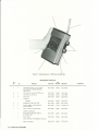
Type 1933
Precision Sound-Level Meter
and Analyzer·
(GR 1940 POWER SUPPLV AND CHARGER)
c
©GENERAL RADIO COMPANY 1973
Concord, Massachusetts, U .S .A. 01742
Form 1933-0100-C
November, 1974
10-5556
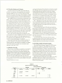
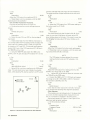
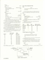
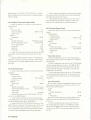
Specifications
This instrument carries U.S. Bureau of
Mines approval for use in gassy coal
mines - Approval No. 2G-2544.
Specifications meet ANSI S1.4 ·1971 for Type 1 (precision) SoundLevel Meters; I EC 179-1965 for Precision Sound -Level Meters; 1EC
123-1961 for Sound-Level Meters; ANSI S1.1 1-1966 f or Octave,
Half-Octave, and Third-Octave Band Type 0 Class II Filter Sets; I EC
225-1966 for Octave, Half-Octave, and Third-Octave Band Filters
for the Analysis of Sound and Vibrations; and Proposed I EC 179
amendment for impulse measurement.
Level Range : 10 to 130 dB re 20 ~N/m 2 with 1-in. microphone, 20
to 140 dB with ~-in. microphone, in 10-dB steps.
Typical minimum measurable level - w ith 1-in. microphone, 22 dBA;
with ~-in. microphone, 31 dBA; lower in octave bands.
Frequency : 5 Hz to 100 kHz essentially flat response, 10 octave
bands with center frequencies from 3 1.5 Hz to 16 kHz; plus A, B,
and C weighting.
Display: METER : 20-dB scale linearly marked in dB and lower,
center, and upper values automatically indicated on scale. Highest
accuracy obtained by using upper 10 dB as measuri ng range. RESPONSE: Fast, slow, absolute peak, and impulse (per I EC 179
amendment), pushbutton selected. Precise rms detection for signals
with <: 20-<:IB crest factor at full scale; crest-factor capacity great er
below full sca le. OVERLOAD : Signal peaks monit ored at 2 critical
points to provide positive panel-lamp warning. RANG ING : Automatic system (OPTI-RANGE) maximizes analyzing range and signalto-noise ratio for each level range-control setting; manual control
provides override.
Filters: WE I GHTING : A, B, C, and flat; pushbutton selected.
OCTAVE BANDS : 10, manually selected, with 3.5 ±1-<:IB attenuation at nominal cutoff, > 18-<:IB attenuation at ~and 2X center
frequency, > 70-<:IB ultimate attenuation. EXTERNAL FI LTERS
can be substituted for internal weighting networks and oct ave-band
filter~; connect to 2 miniature phone jacks.
Input: ~-i n . or 1-in. electret-condenser microphone with flat
response (random or perpendicular incidence); mounted with
detachable preamplifier o n 12-in. extendible mast, or on 10-ft.
extensio n cable supplied, or on 60-ft. cable available. Input can also
be from tape recorder . INPUT IMPEDANCE : 2 GU.// <3 pF.
Output:- SI GNAL OUTPUT : 0.5 V rms behind 60Qn corresponding
to full-scale met er deflection, any load permissible. RANGE CODE :
Contact closure provides sound-level-meter range information t o
1935 Cassette Data Recorder. DETECTED OUTPUT : 4 .5 V de behind 4.5 kfl corresponding to full-scale meter deflection, output is
linear in dB at 0.1 V/dB over 60-<:IB range (40-<:IB normal range plus
20-<:IB crest-factor allowance), any load percnissible.
Calibration : FACTORY : Fully tested and calibrated to all specifications; acoustical response and sensitivity are measured in a free
field by comparison with a WE640AA Laboratory Standard Microphone whose calibration is traceable to the U.S. National Bu reau of
Standards. ON -S ITE : Built-in calibrator provides quick test of electrical circuits; GR 1562 Sound- Level Calibrator is available f or simple test of over-all calibration, including microphones.
Environmental : Performance meets specifications of standards listed
above. TEMPERATURE : -10 to +50° C operating, -40 to +60°C
storage with batteries removed. HUMIDITY : 0 to 90% RH. VI BRAT ION AND M ICROPHONICS : ConformtoapplicableANS I and I EC
standards.
Noise Floor: With 1-in. electret mike, 17 dBA; with
26 dBA. Both lower in octave band measurements.
~-in.
electret
'
Accessories Supplied: Microphone attenuator, tool kit, 10-ft. microphone extension cable, batteries.
Accessories Available : 1940 Power Supply and Charger, electretcondenser microphones. ceramic microphone cartridge and adaptor.
earphone, tripod, cables, and windscreens.
Power: 4 alkali ne energizer C cells supplied provide "' 20-h operation; 1940 Power Supply and Charger allows line operation of 1933
and includes rechargeable batteries and charging source. Battery
check provided on 1933.
Mechanical: Small, rugged, hand-held case with standard 0.25-20
threaded hole for tripod mounting. DIMENSIONS (wxhxd) : 6.25 x
9 x 3 in. (159 x 229 x 76 mm). WEIGHT : 5.51b (2.5 kg) net , 10 lb
(4.6 kg) shipping.
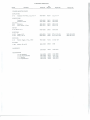
Description
1933 Precision Sound-Level Meter and Analyzer
(Conforms to IEC 179 and ANSI S1.4-197 1, Type 1)
Wit h ~-in. and 1-in . flat random-incidence
response Electret-Condenser Microphone
With ~-in. flat random-incidence response
Electret-Condenser Microphone only
1933 Precision Sound-Level Meter and Analyzer
(Conforms to I EC 179 - recommended for
European countries)
With %-in. and 1-in. flat perpendicularircidence response Electret-Condenser
Microphones
With %-in . flat perpendicular-incidence response
Electret-Condenser Microphone only
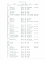
Accessories Available
El ect ret-Condenser Microphones
Flat random-incidence response, 1-in.
Flat perpendi cular-incidence response, 1-in .
Flat random-incidence response, ~-in.
Flat perpendicular -incidence response, Ya-in.
Ceramic Microphone Cartridge and Adaptor, 1-in.
Earphone
Tripod
Cables
Microphone extension cable, 60ft.
Miniature phone plug to 1933 microphone mast
Miniature phone plug to double banana plug
Miniature phone plug to standard phone plug
Miniature phone plug to BNC
Windscreens. reduce wind noise, protect against
contaminants
For 1-in. microphone, set of 4
For y,.in. microphone. set of 4
1562-A Sound-Level Calibrator
Battery , spare for 1933, uses 4
Catalog
Nu mber
1933-9700
1933-9701
1933-9702
1933-9703
1961-9601
1961-9602
1962-9601
1962-9602
1560-9570
1935-9601
1560-9590
1933-9601
1933-9602
1560-9677
1560-9678
1560-9679
1560-9521
1560-9522
1562-9701
8410-1500
Warranty
We warrant that this product is free from defects in material and workmanship
and, properly used, will perform in full accordance with applicable specifications.
If, within a period of ten years after original shipment, it is found, after examination by us or our authorized representative, not to meet this standard, it will be repaired or, at our option, replaced as follows:
•
No charge for parts, labor or transportation during the first three months after
original shipment;
•
No charge for parts or labor during the fourth through the twelfth month after
original shipment for a product returned to a GR service facility;
•
No charge for parts during the second year after original shipment for a product
returned to a GR service facility ;
•
During the third through the tenth year after original shipment, and as long
thereafter as parts are available, we will maintain our repair capability and it will
be available at our then prevailing schedule of charges for a product returned to a
GR service facility .
This warranty shall not apply to any product or part thereof which has been
subject to accident, negligence, alteration, abuse or misuse; nor to any parts or
components that have given normal service. This warranty is expressly in lieu of
and excludes all other warranties ex pressed or implied, including the warranties
of merchantability and fitness for a particular purpose, and all other obligations
or liabilities on our part, including liability for consequential damages resulting
from product failure or other causes. No person, firm or corporation is authorized
to assume for us any other liability in connection with the sale of any product.
Condensed Operating Instructions
a. Lift the t op cover, install the desired microphone and
extend the microphone mast to its full length.
b. Set the MANUAL OVERRIDE contro l (under top
cover) to AUTO. Push in the knur led MAX MIKE dB
contro l (left side panel) and turn it to the position
indicated by the chart inside the top cover. T he proper
setting is given adjacent to the serial number of the
microphone being used. (The serial number of the microphone is marked on the ring which is visible inside the
threaded end. When the 10 dB Attenuator is used with the
1/2 inch mike, its serial number governs.)
c. Push the ON-OFF button (front panel) to t urn the
instrument on and then the BAT CHECK button. The
meter shou ld indicate above the BATTERY mark. Again
press and then release the BAT CHECK button to return
the instrument to normal operation.
d. use the dB LEVEL control (lower major control on
right side panel) to align the CAL arrows on the "MAX
Ml KE dB" control (left side panel). Select the 1 kH z octave
band using the BAND control (upper major control on right
side panlll) and set the SOURCE control (under top cover)
to CAL. The meter shou ld read at full scale, indicating that
the instrument is in cal ibration and ready fo r use. If it does
not, the reading may be adjusted using t he CAL screwdriver
cont ro l located on the top panel, under the top cover.
e. Set the SOURCE control to A orB as indicated by the
cover chart, adjacent to the serial number of the microphone in use,and the instrument is ready for operation.
f. Select WEIGHTING using the BAND control and push
the desired WEIGHTING button (A, B, Cor FLAT on the
front panel). Adjust the dB LEVEL control for an on-scale
meter deflection and read the meter.
g. To measure an octave band level, select the desired
band using the BAND control, adjust t he dB LEVEL
control for an on-scale met er deflection and read the meter.
h. The meter characteristic is normally at FAST. It may
be set to SLOW by pressing the METE R SL OW butt on on
the front panel. To select IMPULSE or PEAK (IMPACT).
check that the slide switch on the right side panel is set to
the appropriate position and then push the METER I MP
button on the front panel. Note that t he SLOW and IMP
buttons are not interlocked so that one must be released
before the other can be depressed.
Introduction-Section 1
1.1 PURPOSE . . . . . .
1.2 DESCRIPTION . . . .
1.3 CONTROLS, CONNECTORS AND INDICATORS
1.4 ACCESSORIES SUPPLIED
1.5 ACCESSORIES AVAILABLE
1.6 SOUND ANALYSIS SYSTEMS
1.7 POWER SUPPLY AND CHARGER .
1.1 PURPOSE.
The Type 1933 Precision Sound-Level Meter and Analyzer is a light-weight, portable sound analyzer intended to
make precision sound-level measurements and octave band
analyses. It operates for 20 hours on self contained
batteries and is ideally suited for field use. Its unique
"opti-range" design permits one-knob control of the level
range. In addition to making measurements on-site, the
1933 operates with its accessory 1935 Cassette Data
Recorder to collect data for later analysis in a laboratory.
The 1933 is capab le of making all measurements
required under the Safety and Health Standards of the
Wa lsh-Healey Public Contracts Act (4 1USC 35 1, et seq.)
and the Occupational Safety and Health Act (OSHA) of
1970 (84 STAT. 1590) including the measu rement of the
absolute-peak sound-level of impact sounds.
The 1933 complies fully with the following standards:
ANSI Standard Specification for Sound-Level Meters.
S1.4- 197 1, Type 1 (Precision)
I EC Recommendation Publication 179-1 965; Precision
Sou nd-Level Meters
Current Draft Supplement to I EC Publ ication 179; Precision Sound-Level Meters. Additional requi rement s for
the measu rement of Impulsive Sounds
IEC Recommendation Publicat ion 123-1961. Sound-Level
Meters
ANSI Standard Specifications for Octave. Half-Octave. and
Third-Octave Band Fi lter Sets, S1.1 1-1966. Type 0,
Class II.
I EC Recommendation Publication 225-1966 Octave. HalfOctave and Third-Octave Band Filters For the Analysis
of Sounds and Vibrations.
1·1
1-1
1-1
1-4
1-6
1-6
1-6
impulse prec1s1on sound-level meter and an octave band
spectrum analyzer. It i'lcludes A. B. and C weighting
characteristics and t en octave band filters with band center
frequencies from 31.5 Hz to 16kHz. It has an additional
flat frequency response extending from 5 Hz to 100 kHz.
Ex ternal f ilter jacks permit the use of speci al weighting or
fi lters in place of the built-in filter network s. The instrument has three selectable detector systems· ( 1) a true rms
detector with fast or slow characteristics, (2) an impu lse
detector that indicates the peak of the short time rms value
and (3) an absolute peak detector. The indicating meter has
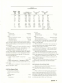
a linear decibel scale that covers a range of 20 dB. T here are
thirteen selectable 20 dB ranges allowing the instrument to
read directly levels ranging from 10 to 150 dB re
20/p N/m 2 with appropriate microphones.
The 1933 is available with 1 inch and 1/2 inch
microphones. The microphone is connected to a detachable
preamplifier which is mounted on an extendable mast. Gain
can be preset for any two microphones so they can be
quick ly changed withou t the need for calibration.
The co ntrols and indicators are arranged conven iently
and efficiently on the instrument. A unique automatic
system ("opt i-range") el iminates the need for multiple or
concentric level controls (attenuators) normally required
with all spectrum analyzers. An ac signal output is provided
for driving other equipment such as analyzers. graphic level
recorders. or magnetic tape recorders. A de output.
proportional to the logarithm of the det ected signal (linear
in decibels w ith a range of 60 dB). is available for driving a
de record er. A multi-pin data output connector provides
range data and signal to the compan ion G R 1935 Cassette
Data Recorder.
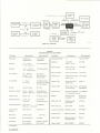
1.3 CONTROLS, CONNECTORS AND INDICATORS
1.2 DESCRIPTION
The 1933 Precision Sound-Level Meter and Analyzer is a
portable sound analyzer including the faci lities of an
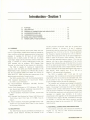
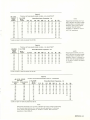
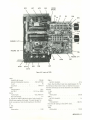
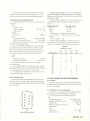
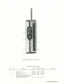
The controls, connectors. and indicators are ident ified in
Figures 1-1. 1-2. and 1-3; their funct ions are described
in Tables 1-1. 1-2.and 1-3.
INTRODUCTION 1-1
11
5
6
7
8
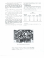
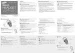
Figure 1-1. Controls a nd indicators
for 1933 . (Front view). The
microphone mast (u pper right )
is elevated, but not extended.
9
10
Table 1-1
CO NTROLS A ND IN DICATO RS
Fig. 1-1
Name
Na me
Meter Face
Description
Recessed met er with dB scale adj ust able by means of dB LEVEL knob
on right side panel.
Function
1. Indicates dB levels ranging f rom 10 dB bottom scale to 150 d B
top scale. Eleven of thirteen ranges are select ed by the dB level
knob. The overall ranges: 10-130, 20-140 and 30-150 dB are det ermined by the MAX M I KE dB knob (left side panel).
2. Indicates condition of ba ttery when BAT CHECK button is
depressed.
3. Ind icates calibration condition- Full Scale- when SOURCE
(top panel) and MAX Ml KE dB (left side panel) are at CAL and the
octave band center f requency is 1 k H z.
2
A, B. C, F L A T
(or EXT)
buttons
4 inter locked latching pushbut tons
Selects A, B, o r C weighting character istic or Flat response (5 Hz100 k H z) when instr ument is in W EI GHTI NG mode.
3
Octave Band/
Weighting
Indicator
11 posit ion dr um indicator driven
with BAND switch knob on right
side panel
Indicates geometric center f requency of the selected octave fi lters
and indicat es when inst rument is in WE IGHT ING mode. Marked
from left to righ t , 31.5 Hz, 63 Hz, 125 Hz, 250 H z, 50 0 Hz, 1 kHz,
2kHz, 4kHz, 8k Hz, 16kHz, and weighting.
1-2 INTRODUCTION
Table 1-1 (contl
CONTROLS AND INDICATORS
Fig. 1·1
Ref.
Name
Description
Function
4
BAT CHECK
button
Latching pushbutton with pushrelease action
Selects battery check mode. Can be leh in battery check position
so battery condition can be monitored when instrument is used as
preamplifier.
5
BAND switch
Knob- 11-position rotary switch
Selects one of 10 octave BAND center frequencies or WE IGHTING mode.
6
ON/OFF
button
Latching pushbutton with push
release action
Turns instrument ON when depressed.
7
dB LEVEL
Knob-11-position rot ary switch
Selects meter range as indicated on meter face.
8
MET ER IMPSLOW buttons
2 latch ing pushbuttons with push
release action so both buttons can
be released.
IMP button selects impulse or peak meter characteristics depending
on position of IMPULSE/PEAK (IMPACT) switch on right side panel.
SLOW button selects slow meter characteristics. When IMP and
SLOW buttons are released the meter characteristic is fast.
9
OVER LOAD
indicator
Lamp
Illuminates when an overload condition occurs indicating t hat the
meter reading is invalid. Also indicates in the MANUAL OVERRIDE mode, when the dB level control has been incorrectly set.
10
IMPULSE/
PK( IMPACT)
11
2-position slide switch (on side)
Determines whether I EC impulse response or peak response will be
selected by the panel METER-IMP button.
Preamplifier latch button
T o remove preamplifier, push button and pull unit off.
3
2
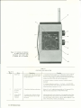
Figure 1-2. Top surface of 1933,
shown with cover open for ac·
cess to controls. The microphone
mast (1 -in. unit installed) is shown
in stowed position. The Y.z-in.
microphone in its storage socket
is at lower right.
4
Table 1-2
TOP PANEL CONTROLS AND CONNECTOR
Fig. 1-2
Ref.
1
Name
SOURCE
Description
4-position rotary switch
Function
Selects gain of instru ment to accomodate the source being used
and selects internal calibrator.
2
CAL
Recessed screwdriver control
Adjusts overall gain of instrument for calibration.
3
MANUAL
OVERRIDE
7 -position rotary switch
Selects normal AUTO operation and serves as manual input range
control to set maximum input level.
4
NONE
Microphone Preamplifier and
Extendible Mast
Input connection from microphone.
INTRODUCTION 1-3
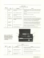
Table 1-3
CONTROLS AND CONNECTORS
Fig. 1-3
Ref.
%-in
MIKE
Name
Description
EXTERNAL
POWER (Not
labeled)
5-flush mounted
banana plug
receptacles.
2
DATA OUT
Miniature 9-pin
connector
Provides connection t o GR 1935
Cassette Data Recorder
3
TO EXT.
F ILTER
Miniature phone
jack
Connects to input of external
filter (minimum load impedance
is600 n)
4
FROM EXT
F ILTER
Miniature phone
jack
Connects to output of external
filter (input impedance 60 kn)
5
MAX MIKE dB
Concentric dial and
knurled knob
Selects range of dB level control to match sensitivity of
microphone in use. Dot on rim
of knurled knob aligns with
"MAX Ml KE dB" dot on inner
dial according to information
in table inside top cover.
For cal ibration, aligns arrow C
with arrow CA L by turning dB
LEVEL control on right side.
6
METER OUT
DC
Miniature phone
jack
Provides 4.5 volts de output
behind 4.5 kn corresponding
to full scale meter deflection.
Linear in dB at 0 .1 V /dB over
60 dB range. Any load resistance can be connected.
7
SIGNAL OUT
AC
Miniature phone
jack
Provides ac signal output of 0.5
volt s rms behind 600 n corresponding to fu ll scale meter def lection, any load permissible.
8
Battery connections
8-spri ng battery
contacts
Makes connections to 4 C cells
(a lkaline or rechargeable NICAD).
Sl iding panel covers and holds
batteries in place.
TR IPOD mount
(not shown)
located on rear
panel.
1/4-20 threaded
bushing
Permits mounting on a t ripod.
10 dB
ATTENUATOR
3
2
1
•
8
Figure 1-3. Side-panel controls and indicator;
cover for DATA OUT jack in foreground.
Function
Provides connection to 1940
Power Supply and Charger
(See Appendix)
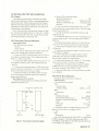
1.4 ACCESSORIES SUPPLIED
1.5 ACCESSORIES AVAILABLE
The accessories supplied with the 1933-9700, 9701,
9702 and 9703 Precision Sound-Level Meter and Analyzer
are listed in Table 1-4.
The accessories available for use with the 1933-9700,
-9701, -9702, -9703 Precision Sound- Level Meter and
Ana lyzer are listed in Table 1-5.
1-4 INTRODUCTION
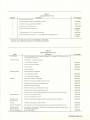
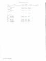
Table 1-4
ACCESSORIES SUPPLIED
Quantity
4
2
Part Number
Description
Batteries (alkal ine C cells)
10-ft EXTENSION CABLE (preamplifier to mast)
1933-9600
Miniature phone plugs (Switchcraft 850-PL)
4270-1110
Screwdriver f or CAL adjustment
(1933-2200)
Electret Condenser Microphone, Y."
1962-9601
or -9602*
10 dB attenuator f or 1/2" Electret microphone
1962-3200
Electret Condenser Microphone, 1" (with 1933-9700 and 1933-9702 only)
1961-9601
or -9602*
•Microphone with -9601 suffix supplied wi th 1933-9700 and 1933-9701
Microphones with -9602 suffix supplied w ith 1933-9702 and 1933-9703
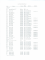
Table 1-5
ACCESSORIES AVAILABLE
Name
BATTERIES
MICROPHONES
MICROPHONES
CABLES
Part Number
Description
A lkaline Energizer C cells (4 required) Burgess AL 1, Eveready E93, Mallory MN1400
or equivalent (4 requ ired)
(F lat Random Incidence Response)
1 inch Electret Condenser
1961 -9601
1/2 inch Electret Condenser
1962-9601
1 inch Ceramic
1560-9570
1/2 inch Ceramic
1972-9601
(Flat Perpendicular Response) :
1 inch Electret Condenser
1961-9602
1/2 inch Electret Condenser
1962-9602
Microphone extension cable , 60ft.
1933-9601
Min iature phone plug t o 1933 microphone mast
1933-9602
Min iature phone plug to double banana plug
1560-9677
Miniature phone plug to BNC
1560-9679
Miniature phone plug to standard phone plug
1560-9678
Miniatu re phone plug to standa rd phone jack
1560-9680
Miniature phone plug to special double banana plug (for Simpson 2745 recorder)
1560-9675
For 1/2 in. microphone, set of 4
1560-4522
For 1 inch microphone, set of 4
1560-4521
SOUND-LEVEL
CALIBRATOR
Provides a precise sound-pressure level at five ANSI preferred frequencies
1562-9702
TRIPOD
Thread mounts (Y.-20) t o back of 1933
1560-9590
DATA RECORDER
Two channel , two track magnetic tape recorder using the Phil ips Cassette format
1935-9701
POWER SUPPLY
AND CHARGER
Dummy Microphone
Provides for line operation of 1933 and for charging NICAD batteries (supplied w ith
Power Supply and Charger).
35 pF BNC .460-60
1940-9701
WINDSCREENS
1560-9609
INTRODUCTION 1-5
1.6 SOUND ANALYSI S SYSTEMS
The 1933 Precision Sound-Level Meter and Analyzer is
available as part of six comp lete sound analysis systems.
Each system is made up of the Sound-Level Meter and
Analyzer with selected accessories packaged in a durable
traveling case. The case has foam liners with cu touts to
accommodate components of the system. A file folder is
supplied for storage of instruction manuals. notes. and data.
Sound-Analysis Systems 1933-9714 and -9715
These systems are assembled in an attache case. 19339714 (with random incidence microphones) and 19339715 (with perpendicular incidence microphones). Case
dimensions are L x W x D = 18-3/8 x 15 x 6 1/4 inches
overall. They include all of the accessories listed in Table
1-4 for the 1933-9700 and 9702 and in addition the following :
1Carrying and storage case (attache size)
1 - Windscreen for 1 inch microphone
1 -Windscreen for 1/2 inch microphone
1Dummy microphone 1560-P9 (35 pf to simulate
1/2 inch electret-condenser microphone)
1Sound-Level Calibrator, 1562 with: Instruction
Manual
Adaptor for 1 inch microphone
Adaptor for 1/2 inch microphone
Battery
1Earphone (ear-insert type) for monitoring signal
from 1933.
Sound Analysis Systems 1933-9710 and -9711
These systems include more equipment than the 19339714 and -9715 systems. Case dimensions are L x W x D =
22-3/16 x 15-3/8 x 8-5/8 inches overall. They include all
the accessories listed in Table 1-4 for the 1933-9700 anci
-9702 and in addition the following:
1Carrying and storage case (carry on size)
1 - Windscreen for 1 inch microphone
1- Windscreen for 1/2 inch microphone
1Dummy microphone 1560-P9 (35 pf to simulate
1/2 inch electret condenser microphone)
1- Sound-Level Calibrator 1562 with: Instruction
Manual
Adaptor for 1 inch microphone
Adaptor for 1/2 inch microphone
Battery
Carrying case
1-6 INTRODUCT ION
111-
60ft. microphone extension cable on reel
Tripod
Earphone (ear-insert type) for monitoring signal
from 1933.
Sound Analysis System 1933-9712 and -9713
These systems include all the components of the 19339710 and -97 11 systems plus a companion cassette data
recorder and its accessories. Case dimensions are L x W x
D = 22-3/16 x 15-3/8 x 8-5/8 inches overall. They include
all the accessories included with the 1933-97 10 and -9711
systems. and in addition the following:
1
5
Cassette Data Recorder 1935-9700 with its accessories including
30 minute standard cassette
Batteries (alkaline c cells)
Coiled cable to connect Sound Level Meter and
Analyzer to Data Recorder.
Playback cable to connect output of recorder to
input at mast of analyzer.
1.7 POWER SUPPLY AND CHARGER
The 1940 Power Supply and Charger allows the 1933
Precision Sound-Level Meter and Analyzer or the 1935
Cassette Data Recorder to be operated from the power line
independently of its internal batteries and also serves as a
battery charger. The Power Supply and Charger is supplied
with a set of five rechargeable N ICAD batteries (four
required for 1933, five for 1935) to replace the alkaline C
cells.
The analyzer plugs directly into the Power Supply and
Charger which also serves as a convenient bench stand.
When the supply is connected to a power line, the analyzer
is supplied power from a source independent from the
battery while simultaneously, the batteries are charged.
Alternately, in the BATTERY mode, the instrument will
operate from its batteries whi le mounted on the charger.
Lamps indicate when the charger is connected to an active
power line and when the batteries are fully charged. When
the BATTERY CHARGED light is on, the batteries are
maintained in the fully charged condition by trickle
charging. Power to the charger and instrument may be
switched by external means in the LINE mode. When
power is disconnected the instrument will cease to operate
rather than taking power from its own batteries.
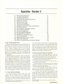
Operation -Section 2
2.1
2.2
2.3
2.4
2.5
2.6
2.7
2.8
2.9
2.10
2.11
2.12
2.13
2.14
2.15
2.16
2.17
2.18
2.19
2.20
SETUP AND CALIBRATION
AUTOMATIC OPERATIOI\J .
OVERLOAD INDICATOR
CHECKING AND CHANGING BATTERIES
SIGNAL OUT AOJACK
METER OUT (DC) JACK . .
USEOFFILTERJACKS . .
CHANGING MICROPHONES
PROXIMITY EFFECTS OF CASE AND OBSERVER
EXTENSION CABLES . . . . . . . .
USE OF MANUAL OVERRIDE CONTROL.
USE OF SOURCE CONTROL
DATA OUT CONNECTOR
USE WITH ACCELEROMETERS
ENVIRONMENTAL EFFECTS .
INTERNALLY GENERATED NOISE.
USE OF ACCESSORIES . . . . .
1940 POWER SUPPLY AND CHARGER .
USING A DC RECORDER . . . . .
USING THE SOUND-LEVEL METER AS A PREAMP
2.1 SET UP AND CALIBRATION
Before making measurements with the 1933, check that
the SOURCE control, MANUAL OVERRIDE control, and
MAX Ml KE dB control are properly set and that the
battery voltage is adequate. See 2. 12 Use of Source
Control , 2.11 Use of Manual Override Control, 2.8 Changing Microphones and 2.4 Checking and Changing the
Batteries for procedures. Then check calibration using
either the internal electrical cal ibrator or the 1562 SoundLevel Calibrator.
Calibration should be performed with the 1933 stabilized at the ambient temperature. If this ambient temperature is outside the range of +10° to +35°C (50° to 95° F)
special calibration procedures are required. If an internal
electrical calibration is performed, correct each subsequent
sound-level reading by an amount equal and opposite to
the sensitivity shift of the microphone. The microphone
temperature coefficient is shown on its calibration certifi cate. If an Overall Acoustical Calibration is performed, the
1933 sound-level readings wil l require no further correction. However, be sure to refer to the calibrator's instructions for temperature corrections, if any, to its output.
2-1
2-2
2-3
2-5
2-5
2-5
2-6
2-6
2-6
2-7
2-8
2-8
2-8
2-8
2-9
2-10
2-10
2-11
2-12
2-12
1-kHz octave band using the BAND control (upper major
control on right side panel) and set the SOURCE control
(under top cover) to CAL. Press the ON-OFF button*. The
meter should read at full scale indicating that the instrument is in calibration and ready for use. If it does not, the
reading may be adjusted using the CAL screwdriver control
located on the top panel, under the top cover.
2.1.2 Overall Acoustical Calibration Using 1562
The internal electri cal calibrator checks the overal l
analyzer w ith the exception of the microphone, at a
frequency of 1kHz.* Use the dB LEVEL control (lower
major contro l on right side panel) to align the CAL arrows
on the MAX Ml KE dB contro l (left side panel). Select the
The best method of checking calibration is with the
1562 Sound-Level Ca librato~ which can check the microphone as well as the electrical circuits at five frequencies.
a. Set the BAND swit ch (upper knob right side) for the 1
kHz BAND and press the ON/OFF button.
b. Set dB LEVEL control (lower knob right side) for a
meter range of 120 dB fu II seal e.
c. Set the frequency of the 1562 Sound-Level Calibrator
to 1000 Hz and place it over the microphone on the 1933
using the appropriate coupler adaptor.
d. The meter should read 114 dB ±0.5 dB. If it does not,
adjust the CA L screwdriver control located on the top
panel under the top cover until meter reads 114 dB.
e. If desired, check the 1933 meter readings at other
frequencies. Select the BAND correspondi ng to the frequency setting of the 1562. Alternately, the BAND switch
can be set to WEIGHTING and the FLAT button depressed. The dB levels observed on the 1933 meter should
be within a few t enths of a decibel of the level observed in
step d.
"The accuracy of the lnternal0 calibrator 0 wlll be ±0 .2 dB in the
temperature range between - 10 C and +50 C.
• Note: No warm-up time is required beyond that for the meter
needle to stabilize.
2.1.1 Internal Electrical Calibration
OPERATION 2-1
2.2 AUTOMATIC OPERATION
2.2.1 Selection of Weighting Characteristic
Sound pressure, which is the small variation in atmospheric pressu re caused by a sound or noise, is measured in
terms of newtons per square meter (N/m 2 ). Sound pressure
is usually expressed as a sound pressure level with respect to
a ref erence sound pressure. The sound-pressure level (SP L)
is expressed in decibels and for airborne sounds the
reference pressure is 20 micronewtons per square meter
(20J.LN/m 2 ). The definition of SPL is:
SPL = 20 log .
p
dB re 20 J.!N/m 2
000020
where P is the root-mean-square (rms) sound pressure in
N/m 2 for the sound in question. For example, if the sound
pressure is 1 N/m 2 the corresponding sound-pressure level
(SP L) is 20 log
_ 00~02 =
20 log 50000 = 94 dB. Whenever
"level" is i ncluded in the name of a quantity it can be
expected that the value of the quantity wi ll be given in
decibels and a reference quantity is stated or implied.
The 1933 is calibrat ed in decibels relative to 20J.LN/m 2 as
out Iined above. When the 1933 is in the FLAT mode. the
reading obtained is designated as the "over-all sound-pressure level" or "sound-pressure level" (SPL) .
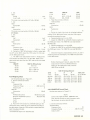
The apparent loudness attributed to a sound varies not
only with the sound pressure but also with the freq uency
(or pitch) of the sound. In addition, t he way it varies with
frequency depends on the sound pressure. This effect is
taken into account by "weighting" networks designated A,
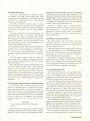
B and C. Responses A, B. and C selectively discriminate
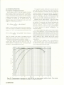
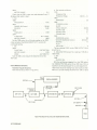
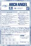
against low and high frequencies as prescribed in the
SOUND LEVE L METER STANDARDS, see Figure 2-1 .
Whenever one of these networks is used, the reading
obtain ed is the "sound level" and the weighting used must
be specified. For example, the following are appropriate
statements: the "A-weighted sound level is 45 dB", "sound
level (A) = 45 dB", o r SLA = 45 dB." The A-weighted
sound level is the one most widely used, regardless of level.
A common practice is to assume A-weighti ng if not
otherwise specified.
It is recommended that read ings on all noises be taken
with all three weightings. The th ree readings provide some
indication of the frequency distribution of the noise. If the
level is essentially the same on all three networks. the sound
probably predominates in f requencies above 600Hz. If the
level is greater on the C network t han on the A and B
networks by several decibels, much of the noise is probably
below 600Hz.
Selection of the weighting mode is accomplished by
turning the BAND switch knob on the right side panel to
the WEIG HTI NG position and pressing the appropriate A,
B, C or FIat button on the front panel.
>lA
0
.........
/
/
""
/
"'"''
~
/
/
10
/
1/
A
B&C
/
/
/
B
20
/
I
30
I
A
/
/
· 40
I
·50
I
I
-60
I
I
-70
· 75
10
50
100
500
1K
5K
10K
50K
l OOK
FREQUENCY - Hz
Figure 2-1 . Frequency-response characteristics for 1933 SLM, with and without standard weighting networks. Curves exclude
the possible acoustical effects of a microphone and are based on a 35-pF·source impedance.
2·2 OPERATION
2.2.2 Meter Characteristic
Three meter characteristics (rms, impulse and impact)
are available in the 1933. The rms det ector has a FAST
response and a SLOW response. The impulse detector meets
the draft I EC requirements and the impact detector
provides a peak measurement.
The FAST rms detector is used for steady or, varying
sound levels where meter fluctuations do not exceed 3 dB,
or where the detector is required to f ollow fast changes in
level such as in automobile or aircraft pass-by measurements.
The slow rms detector has a longer averaging time
characteristic than FAST. The response is approximately
that of an RC circuit with a time constant of 0.5 seconds.
When the signal is of sufficient duration to allow the meter
pointer time to settle or, for a time varying signal, if level
does not change too quickly vs time, this characteristic will
give a more accurate result than FAST.
The impu lse detector is used for impu lsive noises such as
drop hammers or punch presses. This characteristic is
specified in the current draft supplement to I EC Publication 179 and gives a better approximation of subjective
loudness for this type signal than does the rms characteristic.
The Peak (Impact) detector is used to measure the
absolute peak level of a signal. The measurement of peak
level is required by the Walsh-Healey and t he Occupational
Safety and Health Act.
When both t he METER-SLOW and METER-IMP buttons
on the front panel are in their normal "out" position, the
1933 has a FAST response. To select SLOW, depress the
SLOW button. To select IMPULSE or IMPACT (PEAK) set
the slide switch or the right side panel to the appropriate
position and depress the IMP button on the front panel.
Not e that the SLOW and IMP buttons are not interlocked
so that one must be released before the other can be
depressed.
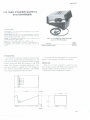
2 .2.3 Extension of Mast and Selection of Microphone Angle
The extendible mast arrangement permits the microphone to be positioned about 12 inches from the instrument case and thus avoids, in most cases, the necessity of
using a cable and tripod. To ex tend the mast, open the top
cover, pull the microphone and preamplifier into an upright
position and then withdraw the mast. The mast is detented
to lock in place when fully extended. The microphone/
preamplifier assembly can be set at any angle over an arc
of 180°.
CAUTION
Do not attempt to rotate mast. Collapse mast
slowly.
When microphones having uniform random incidence
response are used t he assembly should norma lly be t ilted to
about 20° (F igure 2·5). When microphones having uniform
perpendicular incidence response are used, the assembly
should normally be set to a 90° position (Figure 2-6). The
mast (not t he assembly) should then be directed at an angle
perpendicular t o a line connecting the source and the
operat or. This angle will produce the least error in frequency response due to the presence of the instrument case and
operator in t he sound field (see section 2.9).
Indoors, in a reverberant field, a microphone having a
uniform random incidence response will produce a more
accurate result than a microphone having a uniform
perpendicular incidence response. Also, in a reverberant
field, there is little to be gained in accurately directing the
mast and microphone.
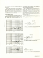
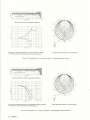
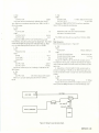
2.2.4 Making an Octave Band A nalysis
The 1933 has ten octave band filters with center
frequencies ranging from 31.5 Hz to 16 kHz. The magnitude and phase response characteristics of the filters are
shown in Figures 2.2 and 2.3.
Measuring octave-band levels with the 1933 is as simple
as measuring sound-level. The "opti-ranging" system operates to ensure that the analyzer is never overloaded, and it
is unnecessary to make a FLAT ("all pass") measurement
before making t he octave-band analysis.
Simply select an octave band center frequency with the
BAND control (upper control on right side of case). adjust
the dB LEVE L control (lower control on right side of case)
for an on-scale meter deflection and read the meter. The
response is unaffected by weighting button position.
2.3 OVERLOAD INDICATOR
When the OVER LOAD lamp is lit (lower right corner of
meter), meter readings are invalid. The purpose of this lamp
is to warn the operator when any of the circuits in the
analyzer have been overloaded and also when the MANUAL
OVERRIDE control has been used incorrectly.
It should be realized that a sound-level meter that does
not have an overload det ect ion system may produce a
meter indication that appears normal but is invalid because
of overload. This problem arises with impact sounds that
have very high peak-to-rms ratios (crest factor) such as
those produced by typewriters and key punches. The 1933
is especially suitable for such difficult measurements
because it has a crest f actor capacity of 20 dB at full scale
on the meter (proportionately higher below full scale) in
addition to the overload detection system.
The overload lamp will light when the peak level of the
signal at any stage is high enough to overload that stage. In
addition when the analyzer is used in its manual mode, it
will also light if the main level range control is set to give a
full scale range higher than, or more than 50 dB lower
than, that indicated by the MANUAL OVERRIDE control.
When t he analyzer is being used in its normal automatic
mode, set the level range control to a higher (in dB) range
OPERATION 2-3
0
\
~
10
\
IJ
II
20
CD
"0
~
~30
w
-'
w
I
>
~40
1\
\
1\
1\
I
-'
w
a:
\.
1\
I
v
50
I\
"\
/
60
·ro
I
~
v
\
/
\
1\
/
Fo
Fo
10
5
Fo
2
Fo
2Fo
5Fo
RELATIVE FREQUENCY
Figure 2-2. Normalized ma!lnitude response of the octave-band
filter in the 1933.
270
180
(/)
90
w
w
0::
<.?
w
0
I
0
1II..
i:
(f)
w
-90
(f)
<t
:I:
a..
-180
-270
0.5
I
NORMALIZED FREQUENCY - Hz
2
Figure 2·3. Normalized phase response of the octave-band filter
in the 1933.
2-4 OPERATION
IOFo
19:ZS.2
when an OVERLOAD is indicated. In the manual mode,
check to be certain that the main level range is within the
acceptable range as stated above. If it is, then an OVERLOAD exists which can be eliminated by setting either the
MANUAL OVERRIDE control or the main level range
control to a higher range.
2.4 CHECKING AND CHANGING BATTERIES
Rated accuracy can be maintained only if the batteries
supply more than a certain minimum voltage. This voltage
is indicated by the meter in the BAT CHECK mode. Therefore, the batteries should be checked before checking cali bration or making measurements. With the instrument ON ,
press the BAT CHECK button and observe that the meter
indicates above t he battery mark. If not, slide off the
battery cover on the bottom panel and replace the batteries
being carefu l to observe polarity. Use alkaline energizer C
cells (4 requ ired). Burgess AL 1, Eveready E93, Mallory
Mn 1400 or equivalent. A l kaline energizers will provide
about 20 hours continuous operation. Ordinary f lashl ight
batteries may also be used. The operating time however will
be substantially less.
NOTE
Observe the usual precautions against the formation
of ground loops when using external equipment.
2.5 SIGNAL OUT AC JACK
Thi s jack allows the 1933 to be used as a preamplifier
for a magnetic tape recorder, a graphic level recorder or
other devices. It may also be used for driving earphones.
This signal is taken from the output of the analyzing
amplifier/attenuat or ahead of the detector. It is an ampli-
• 20
,_
L
,,....,..
H"
•1 0
fied replica of the input signal with the weighting set to
FLAT or of the weighted or filtered signal otherwise. The
rms va lue of the output (open circuit) voltage corresponding to a full scale indication on the meter is 0.5 volts. The
source impedance is 600 ohms and any load can be
connected without affecting the meter reading or linear
operation of the output circuits.
2.6 METER OUT (DC) JACK
This jack is intended primarily to provide a detected
(DC) signal, linear in decibels for driving a DC recorder. The
recorder can be used to display the Fast, Slow, Impu lse or
Peak sound level as a function of time or octave band
pressure levels as a function of frequency. Details of connection and use of a DC recorder are given in section 2.19.
The DC signal available at the METER OUT (DC) jack can
also be used to drive a meter to provide a w ide dynamic
range display or to trigger an alarm.
The signal at this jack is 4.5 V behind a resistance of 4.5
kS1 correspondi ng to fu II scale on the meter. Each 0.1 volt
change in open circuit voltage corresponds to a 1 dB change
in level (i.e., the sensitivity is 0.1 V /dB). The useable range
in open circuit outpu t voltage is 6.5 volts to 0.5 volts or a
linear-decibel range of 60 dB. Any load resistance can be
connected. If the output is short circuited, it produces a
current of 1 ma at full scale on the meter.
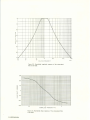
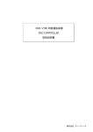
Figure 2.4 shows the sine wave frequency response of
the 1933 measu red at the Meter Out (DC) jack at six
different levels on the 110 dB range. The response is
plotted f or all four meter detector charact eristics; FAST,
SLOW, IMPULSE and PEAK and includes the low frequency coupling effect of the 1962 microphone.
/
PEA K
--
/.
_.-1 PUL E
PEA l<- f.-
IS
PU
-
E
,<T
EA
10
i<T
*
I
-20
r-'\0
j
~
30
-l!E
p
~ G"
---~
~
f--.+
<T
J
Ml'U
HI
f':i:.H<T
10
50
100
500
1K
5K
10K
50K
1OOK
FRE QUENCY Hz
Figure 2-4 . Comparative frequency responses of PEAK, IMPULSE, FAST and SLOW measurement modes
of the 1933. Readings all taken at METER OUT (DC) jack.
OPERATION 2-5
2.7 USE OF FILTER JACKS
The two miniature phone jacks (closed circuit type) on
the left side panel, marked TO EXT FILTER and FROM
EXT Fl L TEA can be used to substitute an external filter or
weighting network for the internal ones.
To use the jacks, set the BAND control to WEIGHT ING
and push the FLAT (or ext) button on the front panel. The
internal signal path is now through the phone jacks and wil l
be broken by inserting the phone plugs that connect the
external filter.
The output impedance at the TO EXT FILTER jack is
less than 50 n and the filter connected must have an input
impedance of 600 n or more. The input impedance at the
FROM EXT Fl LTEA jack is 60 kQ and the filter connected
must not have an output impedance of more than 6 kQ.
The maximum voltage (open circuit) at the TO EXT
FILTER jack is about 1 volt peak so that the external fi Iter
should be capable of handling this signal level if the full 20
dB crest factor capacity of the analyzer is to be realized.
2.8 CHANGING MICROPHONES
Because no single microphone is best for all applications,
the analyzer includes a SOURCE control that allows
selection of two preset gains. These gains are adjusted at the
factory to accomodate the microphones supplied w ith the
analyzer. It is therefore not necessary to recalibrate the
analyzer when changing microphones.
When the analyzer is supplied with only a 1/2 inch
electret condenser microphone (1933-9701 and
1933-9703). the gain presets are adjusted to accomodate
both the microphone cartridge and '1:he microphone cartridge w ith the 10 dB attenuator (supplied) in place. When
the analyzer is supplied with both 1/2 inch and 1 inch
electret condenser microphones, the gain presets are adjusted to accomodate the two microphone cartridges only.
The analyzer is not calibrated for use with the 10 dB
Attenuator.
To change gain to accommodate microphones supplied
with the analyzer, it is only necessary to reset the SOURCE
control (under top cover) and adjust the MAX M l KE dB
control according to the block checked in the chart inside
the top cover. Push in the knurled MAX Ml KE dB control
(ltaft side panel) and turn it to the position indicated by the
chart. The proper setting is given adjacent to the serial
number of the microphone b~ing used. (The serial number
is marked on the ring which is visible inside the threaded
AJld of the microphone. When the 10 dB attenuator is used,
its serial number governs.)
The gain presets, R9 for MIKE A and R7 for MIKE B,
may be set to accommodate other microphones (not supplied) or the 'h" electret condenser microphone with the 10
dB attenuator. Proceed as follows:
Install the microphone on the 1933 preamplifier.
Remove the back cover from the Analyzer to expose the
preset controls (see para. 4.4).
2-6 OPERATION
Table 2-1
GAIN PRESET ADJUSTMENTS
MICROPHONE SENSITIVITY
Microphone Sensitivity
Level dB re 1 V/N/m 2
-26to -36
-36to -46
-46to -56
-56 to -66
Level dB re 1 V/j.l.bar
-46to -56
-56 to -66
-66to -76
-76to -86
Setting of
MAX MIKE
dB Control
120
130
140
150
Set the SOURCE control to the position desired for the
new microphone.
Set the MAX Ml KE dB control to the position
indicated in Table 2- 1 for the sensitivity level of the new
microphone. Press in and then turn the knurled knob. Place
the Type 1562 Calibrator set at 1 k Hz over the microphone.
Set the BAND control to WEIGHTING and the dB LEVEL
control for the 120 dB (full scale) range. Depress the C button and adjust the appropriate gain preset control for a
meter indication of 114 dB.
2.9 PROXIMITY EFFECTS OF CASE AND OBSERVER.
Every effort has been made to make the 1933 a
self-contained precision sound-measuring instrument. The
extendible mast and swivel mounting for the microphone
and preamplifier make it possible to avoid in most cases the
necessity of using an extension cab le and tripod to remove
the microphone from proximity to the instrument case and
observer. To achieve most accurate results, always, where
practical, follow these simple rules:
1. Extend the mast to its full length , where it will lock in
position.
2. Stand so the sound source is to your left.
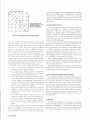
3. When using a random incidence microphone (supplied
with 1933-9700, -9701) set the preamplifier to 20°. When
using a perpendicular incidence microphone, set the preamplifier to 90°. Hold the microphone away from yourself
and other large objects and direct the mast (not the microphone) at an angle perpendicular to a line connecting you
and the sound source. Figures 2.5 and 2.6 show the small
error that may be introduced by the presence of the
instrument case and observer when these rules are followed.
Error curves are given for the 20° preamplifier position and
for the 90° preamplifier position both with and without the
operators presence.
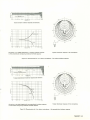
Figure 2.7 shows the error introduced by the instrument
case (no operator present) w hen the preamplifier is in its 0°
position and the mast is pointed at the source. This position
should be avoided if possible.
All error curves were obtained using pure tones in a
free-field (anechoic space) and can be considered "worst
case". For normal industrial or commu nity noise environ-
Sound-Analysis Systems 1933-9710, -97 11 , -97 12. and
-9713 or it may be ordered separately.
Cables are inserted between the removable preamplifier
and the mast. Because the preamplifier and not the
microphone drives the cable, there is no loss or change in
calibration when a cable is used. To install a cable, remove
the preamplifier by depressing the connector latch (small
button visible through hole at connector end of preamplifier) with a pencil or other pointed object and pulling the
preamplifier straight out.
Still longer cables can be used at reduced levels and frequencies. The length depends upon the capacitance of the
cable used. Approximately 1 mA peak is available from the
preamp I ifier for driving a cable.
ments, or indoors. error will be considerably smaller and
can be ignored.
The 10ft cable supplied with the 1933 (1933-9600) or
the 60ft cable available ( 1933-960 1) can be used to allow
both operator and instrument case to be positioned still
farther from the microphone, thus eliminating the proximity errors. The microphone preamplifier is then mounted
on the 1560-9590 tripod or by other means.
2.10 EXTENSION CABLES
A ten f oot extension cable 1933-9600 is supplied w ith
the Sound-Level Meter and Ana lyzer. In addition, a sixty
foot extension cable 1933-9601 is supplied with the
+2
1933
o;
0
-
f('"
:!!
...;;:;
...>
...J
\INSTRU MENT_
CASE ONLY
...J
;:
c...J
...
IE
1\
lh
a
J
A
vv Ill.,.TV' rut
n
l11.
OBSERVER
§ ~ =; :; . . .,.~ ~j: :~=:::::::d</2:::.__./\:_~LI
./
11_1
Figure 2-5. Error introduced by presence of instrument case
and observer in sound field, with preamplifier at 20°.
+2
0
~~~gE ~l
ANALYZER
I~
. tl -.
INSTRUMENT _
CASE AN D
OBSERVER
-
·2
I
10K
1K
FREOUENCY - Hz
I
-
0
o;
...;;:;
I
I~
~
"'
1\
:!!
...J
·2
I
OBSERVER
...>
...
SOURCE
i...J\A
...J
;:
c...J
SOUND~
INSTALMENT
CASE ONLY
J
+2
INSTRU MENT
CASE AHO
I
+2
,.,,
IE
0
v
I
,,
I" I
A
\1
II\ I
y
·2
200
500
fir I
lA I\ I
1J
111
Figure 2-6. Error introduced by presence of instrument case
and observer in sound field, with preamplifier at 90" .
'
v
10K
SK
2K
1K
DeSERVER
f.
Y\.i
20K
30K
FREQUENCY - Hz
o;
:!!
.:>
+2
...J
0
...
...>
\
1933
l
---7\-
r;;.~n
---J,I y_
;:
c...J
'fV i'U I 11,
11 rnuu
T
~~~
,, \.'\. _/
II
IE
Figure 2-7. Error vs frequency introduced by instrument
case alone in sound field, with preamplifier at 0~.
ENVELOPE
OF ERROR
200
500
1K
2K
SK
10K
20K
ac::::::a-~ ~~~gE
.....,.!.1?11
0;:::;:::;::=
"
~
...
ANALYZER
30K
F REOUENCY - Hz
OPERATION 2-7
2.11 USE OF MANUAL OVERRIDE CONTROL
In some cases, for example, when measuring a transient
signal (one avai lable for measurement for only a few
seconds) whose band levels are known approximately, it
may be desirable to override the automatic system and
manual ly set the gain of the amplifier/attenuator circuits
to save the 4-second settling time. A MANUAL OVERRI DE control, used with the dB LEVEL control, provides
standard manual operation for the occasion when the automatic system is not appropriate.
When used in t he automatic (AUTO) mode, provided t he
OVER LOAD lamp is not lit, the 1933 wi ll produce a valid
meter indication even during the 4-second settl ing time.
However, during this period the dynamic range of the signal
at the SIGNAL OUT AC jack (and signal at DATA
OUTPUT connector) wi ll generally not be as high as after
the settling i nterval. Given some know ledge of the expected
overal l level of a transient signal , the settling interval can be
avoided by use of the MANUAL OVERR IDE contro l. For
normal operation , this control is set to A UTO(max ccw).
For manual operation the control functions in exactly
the same way as the input "attenuator" control on a
manual analyzer. It is set in accordance with the expected
max imum overall (i.e. C-weighted or FLAT) level of the
input signal. Set the MANUAL OVERR I DE control to
indicate a ful l-scale level for t he overall signal that is as high
as or higher than the maximum overall level expected in the
transient signal. * (In some cases, it may be possible to
measure the overall (C-weighted or Flat) level of a test
signal in order to establish the correct setting of the
MANUA L OVERRIDE control.) Now select the weighting
network or filter band desired and adjust only the dB
L EVEL contro l for a meter full scale range that is at least as
high or higher than t he maximum level expected in the
selected band. Obviously, the dB LEVEL control must not
be set to a fu ll scale range higher than the full scale range
indicated on the MANUAL OVERR IDE control. Also, the
dB LEVEL control cannot usually be set to a full scale
range more than 50 d B below that indicated by the
MANUAL OVERRIDE control. (An exception is when the
inpu t signal has a low to moderate crest fact or such as, for
example, a square wave or sine wave signal) .
If either the allowed max i mum or minimum settings of
the dB LEVE L con trol are exceeded, the panel OVE ALOAD lamp w ill light to warn the operator.
2.1 2 USE OF SOURCE CONTROL
The SOURCE contro l provides a means for convenientl y
using the Sou nd- Level Meter and Analyzer with several
sources incl uding two microphones, the 1935 Cassette Data
Recorder and possibly an accelerometer. The Ml KE positions A and B normally select preset gains corresponding to
those required for two microphones. In the TAPE position,
* Its MAX dB value should be set at the colored dot corresponding
to the dot adjacent to the microphone check block in the top cover.
2-8 OPERATION
the 1933 has a sensitivity of 0.5 V full scale when the dB
LEV EL control is in its max cw position (least sensitive
meter range). CAL activates the internal cal ibration system.
2.13 DATA OUT CONNECTOR
This is a nine-pin miniature connector located on the left
side panel of the 1933. It is used for interconnection w ith
the 1935 Cassette Data Recorder. When not in use it is
capped. Connection to the Data Recorder is by me'!ns of
the coiled data cable 1935-9630 w hich has a mati ng
nine-pin connector on one end and a fourteen-pin connector on the other. Secure both connectors using t he thumb
screws. This cable completes all connections needed between the 1933 and 1935 Cassette Elata Recorder. Consult
the 1935 Instruct ion Manual for more information on the
use of this combination.
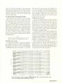
2.14 USE WITH ACCELEROMETERS
The 1933 can be used for v ibration measurement s when
the microphone is replaced with an accelerometer. Three
accelerometers are available. They are Types 1560-P52,
-P53, and -P54. The -P52 is a general-purpose, low-cost unit
with moderate high-frequency performance, the 1560-P53
has a wide frequency range and shou ld be used when
frequenc ies above about 1500 Hz must be measu red, the
1560-P54 is a high sensitivity pickup used to measure very
low acceleration levels. Tabl e 2-2 lists the performance
characteristics of these pick ups w hen used w ith the 1933.
A type 1560-9669 adaptor is required t o connect the
cab le supplied with the pickups to the 1933 preamplifier
input. The adaptor screws onto the preampl ifier in place of
the microphone and the pickup cable plugs into the
adaptor.
Because the dB LEVEL drum indicator on the 1933 can
be set in any of its positions relative to the setting of the dB
L EVEL control using the MIKE MAX dB control, it is a
simple matter to calibrate the 1933 t o be d irect reading in
decibels referred to the ANS I standard preferred reference
level of 10-3 cm/sec2 (S 1.8-1969).
2.14.1 Calibration
The following ca libration procedure is recommended to
make the 1933 direct reading in dB re 10-3 cm/sec 2 ; other
methods can also be used. The procedure requires use of a
Type 1557 V ibration Cal ibrator which generates a reference
level of 1 g rms at a frequency of 100 Hz.
a. When using either the 1560-P52 or the 1560-P53
accelerometers, set the MAX MIKE dB control to 140.
When using the 1560-P54 acceleromet er set the MAX Ml KE
dB control to 120.
b. Set the dB LEVE L control for 120 dB fu ll scale.
c. Mount the accelerometer on the Type 1557 V ibration
Calibrator and adjust the ca librator to produce a level of 1
g rms. (See instruction manual supplied with the calibrator.)
Tab le 2-2
ACCELEROMETER PERFORMANCE CHARACTERISTICSt
Pickup
Type No.
1560-P52
No mina l
Sens.
mv/g
70
1560-P53
1560-P54
Resonant
Freq .
Hz
Acceleration Range•
Frequency Range
Hz
in/sec2
.0036·2700
dB re•
10" 3 cm/sec2
20·140
3200
5- 1600
g
8x10"" to 7
70
27000
5- 14000
8x10... to 7
.0036·2700
20-140
700
5000
5-2500
8x1o·~
.00036-270
0-120
to 0.7
•Minimum l evels measureable only in middle frequency octave bands.
tsee also Table 2·4 .
d. Set the 1933 to WEIGHTING and FLAT and t urn it
ON.
e. Set the SOURCE co nt ro l to preset A or B as desired
and adjust the appropriate gain preset (R9 for A, R7 for B)
for a meter indication of 11 9.8 dB. R9 and R7 are found
under the back cover. See par<1. 4.4 for removal of cover.
2.14.2 Operation
The instruction sheet supplied with the accelerometer
provides specifications and explains how it shou ld be
fastened. Disregard instructions on use of the overall
pick-u p system including the control box. The low frequency limit, when any of the above accelerometers are used, is
determined by the 1933. That is, with the FLAT weighting,
the system (including the accelerometer) will respond
uniformly down to about 5 Hz. The upper frequency limit
is determined by the resonant frequency of the accelerom·
eter. It is usually taken to be about one-half of t he resonant
f requency of th e acceleromet er and is given in Table 2-2.
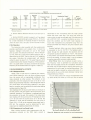
2.15 ENVIRONMENTAL EFFECTS
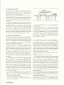
2.15.1 Background Noise
Ideally, when a noise source is measured, the measurement should determine only the direct air-borne sound
from the source with no appreciable cont ribution from
noise produced by other sources. This criterion is met
practically when the background noise is 10 dB or more
below the sound being measured. If the background noise is
not 10 dB below the sound being measured in any given
band, a correction can be applied to the total noise reading
as determined by Figure 2·8.
Take readings with the Sound-Level Meter and Analyzer at
the test position w ith and without the sound source, to be
measured, operat ing. The difference i n read ings determi nes
the correction to be used. For example, if an octave band
level reading w ith the sound source off (background level)
is 77 dB and with the sound source on is 83 dB , the
difference is 6 dB and the correction from the curve of
Figure 2·8 is 1.2 dB so t he corrected octave band level is
8 1.8 dB. The correction must be determined for each
octave band or weighting characteristic of interest.
2.15.2 Precautions at Low Sound Levels
When making low-level noise measurements with the
microphone mounted on t he 1933 mast a sound is
transmitted to the microphone when the meter pointer
strikes the lower meter stop. This sound can cause the
meter pointer to read up scale again and if the instrument is
set to METER FAST, a sustained oscillation can occur. To
avoid this condition use the SLOW meter response or
mount the microphone and preamplifier away from the
Sound-Level Meter and Analyzer using the extension cable
supplied.
Another feed-back effect may occur when an earphone
is connected to the AC OUTPUT. The feedback path is
closed through the path between the earphone and the
microphone causing the earphone to "howl". The solution
to this problem is to separate the earphone and microphone
as much as possible. In ext reme cases, it may be necessary
to use the preamplifier extension cable suppl ied.
Wind Effec ts. When the microphone is used in wind, a
low frequency noise is generated by turbulence caused
when the w ind passes around the microphone. The level of
this noise may be high enough to obscure t he sound to be
measured and in some cases, to overload the analyzer. This
noise can be greatly reduced by using a wind screen. It is
good practice to use a wind screen whenever making noise
measurements out of doors.
The G R wind screens will reduce wind-generated noise
by about 20 dB, for winds up to 25 mph, with no serious
~
9
...J
I
~
7
i
~
... 6
0
w
t;
... :1
...a::
~
»:
0
4
l
t:
a::
~ 2
a::
w
~
I
0
0
2
l
4
:1
6
7
8
9
10
dB DIFFERENCE BETWEEN TOTAL NOISE ll BACKGRO\A'jO ALONE
Figure 2-8. Background noise correction fo r sound measurements.
OPERATION 2-9
8
"':><
u
I
II
·2
instrument is a function of the setting of the dB LEVEL
control. The noise charts in para. 4 .5 show typical internally generated noise levels in dB below full scale for each set-
I
I
1 IN MICROPHONE
WIND SCREEN
0
a:
0
a:
a:
1---
...w
"'0z
~
a:
>
\~\N ~/~~~~~~~~
\
•2
u
z
:;
~
0
~
...a:
200
500
1K
2K
FREQUENCY
SK
10K
....... ......
20K
JOt(
Hz
Figure 2-9. Effect of windscreens on microphone response.
effect on frequency r esponse. There is a slight loss of
frequency response at high frequency as shown in figure
2-9. Since wind noise is concentrated at low frequencies,
using A-weighting to attenuate the noise may help. Also,
the octave bands above 500 Hz are less effected by wind
noise than those below.
2.15.3 Hum Pickup (Magnetic Fields)
The maximum sensitivity of the 1933 to an ext ernal
magnetic field is equivalent to 43 dB(C) when the applied
field is 80 Aim at 60 Hz. Hum pickup is not normally a
problem with the 1933. However, when making measuremen ts near heavy electrical equipment, a check may be
made to see that there is no appreciable pickup of the magnetic field. To make this check, replace the microphone
with the 1560.P9 dummy microphone or other shielded
capaci tor that has the same capacitance as the microphone
being used. With the dummy microphone installed, the
equivalent sound level due to hum should be lOdB or more
lower than the sound level to be measured. Changing the
orientation of the instrument may help.
2.15.4 High Sound Levels (Microphonics)
At very high sound levels, componen ts or wi ring in a
sound-level met er may vibrate and t hereby produce an
interfering noise. The instrument is then said t o be
generating microphonics.
To test for microphonics, replace the microphone with a
1560.P9 dummy microphone and observe whether the
indicated level is less than the level with the microphone
con nected. If the level in the band (or with the weighting)
to be used is not at least 10 dB below the level w ith the
microphone connected , use a 10' or 60' preamplifier
extension cable to allow the instrument to be removed
from the high sound-level area.
2. 15.5 Vibration
The vibration sensitivity of the 1933 is primarily that of
the microphone, which is an equivalent maximum level of
83 dB for 1 g vibration.
2.16 INTERNALLY GENERATED NOISE.
T he dynamic range (fu II scale to noise floor) of the
2-1 0 OPERATION
tings of the dB LEVEL control when the instrument is set
to C weighting as measured at the SIGNAL OUT AC jack
by another octave band analyzer. The dynamic range is also
a function of the capacitance of the microphone and therefore, charts are shown for the 1" and 1/2" electret condenser microphones and the 1" and 1/2" cerami c microphones. All charts apply for the typical microphone sensitivity as given .
The lowest level that can be measured with a sound level
meter is usually taken to be a level 5 dB above the absolute
noise floor of the instru ment. Table 2-3 gives minimum
levels according to this criterion for A, B and C weighting,
F L AT and octave bands and f or all four normally used
microphones.
The internal noise levels of para. 4.5 and those used
here to determine the minimum measureable no~se level are
for a typical instrument, the actual noise floor of any given
instrument can be determined by replacing the microphone
with a dummy source having a capacitance equal to that of
the microphone. The 1560.P9 Dummy Microphone has a
capacitance of 35 pf and is thus suitable as a dummy
source, replacing the 1/2" electret co ndenser microphone.
The 1" electret condenser microphone should be replaced
w ith a source capacitance of 125 pf and the 1" or 1/2"
cera mic microphone should be replaced with· a source
capacitance of about 400 pf.
2.17 USE OF ACCESSORIES
A number of accessories are available for the SoundLevel Meter and Analyzer and the various Sound-Analysis
Systems. The purpose of each is described in the following.
The mini-phone plugs (4270-1110) are used to make
connection to the SIGNAL OUT AC jack, the METER
OUT DC jack, or the Fl L TEA jacks.
The screwdriver is for adjustment of the CAL control
located in the top panel of the instru ment or for adjustment of the internal "preset" controls.
The 1933-9600 and -9601 (10ft. and 60ft.) Ex tension
Cables are for use between the microphone/preamplifier
combi nation and the input connector on the mast of the
1933. They allow the microphone to be positioned remotely from the instrument case and operat or.
The MINE LABEL (1933-0150) is a self-adhesive label
stating that the 1933 has been approved for use by the U.S.
Bureau of M ines. It should be attached t o the instrument as
instructed in the protective instruction folder by those who
intend to use the instrument where the Bureau of Mines
approv.al is required.
The Dummy Microphone (1560-P9) is simply a capacit or
which simulates the capacitance of the 1/2 inch electret
condenser microphone. It is used with the shorting cap in
place to measure internal noise level. The shorting cap can
be removed to allow an electrical signal simulati ng the
microphone source to be applied to the analyzer for testing
and calibration. When connected to the 1933 the loss in
signal through the dummy mike is about 0.5 dB.
The Sound-Level Calibrator (1562) is used to make an
overall (including the nicrophone) calibration check on the
analyzer. It is provided with adaptors to fit the 1 inch and
1/2 inch microphones and generates a sound-pressure level
of 114 dB at five frequencies from 125 to 2000Hz.
The earphone (1935-0410), a small in-the-ear type
earphone, is used to listen to the sound being measured at
the SIGNAL OUT AC jack. It is helpful in determining the
nature or source of a noise and providing assurance that the
analyzer is operating properly.
The tripod (1560-9590), a compact unit with elevating
center post, is used to support the microphone and preamplifier when they are used at the end of an extension
cable. It can also be used to support the complete 1933.
The tripod has a swivel head that permits 0 to 90°
adjustment in one direction and 0 to 20° (for proper
orientation of a microphone with flat random incidence
response) in the other direction. The head has two
concentric removable sleeves for mounting 3/4 inch diameter devices or 1/2 inch diameter preamplifiers. It also has a
standard 1/ 4-20 screw and a locking nut for mounting the
1933. The friction in the swivel can be adjusted by
removing the swivel from the center post of the tripod and
adjusting the allen head screw in the base of the swivel.
The Microphone Attenuator (1962-3200) is a 10 dB
capacitive attenuator to be used with the 1962-9601 or
9602 1/2 inch electret condenser microphones when sound
leve ls above 130 dB are to be measured. This unit is
inserted between the 1/2 inch microphone and the preamplifier input.
The Cassette Data Recorder (1935) is a major accessory
for the 1933 and is supplied with many of its accessories in
the 1933-9712, 9713 Sound-Analysis Systems. Instructions
for the recorder and its accessories are given in the
operating instruction book for the 1935.
1933-9602 miniature phone plug to 1933 mast connector is used to connect the output of the 1935 Cassette Data
Recorder to the input of the 1933. It is supplied with the
1935 Cassette Data Recorder. This cable can also be used to
connect the 1560-P62 Power Supply to the input of the
1933 thus al lowing the 1560-P42 Preamplifier to be
substituted for the 1933 Preamplifier. The 1560-P42 is used
for driving very long input cables.
1560-9677, miniature phone plug to double banana
plug, used to connect METER OUT DC, SIGNAL OUT AC,
or Fl LTER jacks of 1933 to instruments with GR (or
equivalent) binding post terminals.
1560-9678, miniature phone plug to standard phone
plug, used to connect jacks on 1933 to instruments with
standard phone jacks.
1560-9679 miniature phone plug to BNC connector used
to connect jacks on 1933 to instruments fitted with BNC
connectors.
1560-9680, miniature phone plug to standard phone
jack adapts miniature phone jacks on 1933 to connect with
standard phone patch cords. Can be used to connect
SIGNAL OUT AC jack of 1933 to 1556 Impact Noise
Analyzer.
1560-9675, miniature phone plug to special double
banana plug with molded-in 200 n resistor, used to connect
METER OUT DC jack of 1933 to input of Simpson 2745
DC recorder.
0776-9701, shielded double banana plug to BNC connector, used to connect output of G R oscillators and/or
attenuators to input of 1933 through 1560-P9 dummy
microphone.
2.18 1940 POWER SUPPLY AND CHARGER.
The 1940 Power Supply and Charger permits the 1933
Precision Sound-Level Meter and Analyzer to be operated
directly from the power line and also permits use of
rechargeable batteries. There is no change in accuracy when
the 1940 power supply is used. The 1940 is supplied with
rechargeable batteries which are used to replace the alkaline
Table 2-3
TYPICAL MINIMUM MEASUREABLE NOISE LEVELS (dB re 20 !JNim 2
Microphone
Type
)
Typical
Sensitivity
level
dB re
1 V/N/m 2
A
B
c
FLAT
31.5
63
125
250
500
1K
2K
4K
SK
16K
1-in Electret Condenser
-37
22
21
22
32
18
16
14
13
11
11
13
15
17
19
Y:.-in. Electret Condenser
-43
32
35
22
36
42
45
32
30
28
26
25
23
24
24
24
26
39
23
34
16
13
12
11
11
13
14
16
18
21
44
45
56
38
35
34
33
33
35
36
38
40
43
Octave-Band
1-in Ceramic
-40
31
34
24
Y:.-in Ceramic
-62
46
·• Guaranteed mfnimum measurable levels with Y.-in. electretcondenser microphone.
OPERATION 2-11
energizers supplied with the 1933. If the 1940 is to be used
to provide only power line operation, it is unnecessary to
install the rechargeable batteries.
CAUT ION
Do not use the 1940 when al ka line energizers
are in the 1933.
Five recessed jacks on the bottom of the 1933 accept
plugs on t he 1940; fully plug t he instruments together. The
1940 also serves as a convenient bench stand.
To power the 1933 from the 1940 supply, connect the
1940 power cord to a power line and set the BATTERY/
PWR LINE switch to PWR LINE. The PWR LINE lamp will
light when the supply is connected to the power line. Now,
simply operate the 1933 in the normal way. While
operating on PWR Ll NE, the batteries will be charged by an
independent charging supply. The BATTERY CHARGED
light will come on to indicate that the batteries are fully
charged and are being maintained in that condition by
"trickle" charging.
To charge the batteries only, proceed as above but do
not turn on the 1933.
The 1933 may be operated from its batteries when
mounted on the 1940 by setting the BATTERY /PWR Ll NE
switch on the 1940 to BATTERY.
One important feature of the 1940 Power Supply and
Charger is that line power may be connected and disconnected by external means. When power is disconnected, the
1933 wi ll cease to operate and wil l not drain its batteries.
2.19 USING A D.C. RECORDER
The METER OUT DC jack provides a DC signal linear in
decibels for driving a DC recorder. A DC recorder for use
with a portable system such as the 1933 should be small,
lightweight, and battery operated. In addition, it shou ld
have fast writing speed and a range of chart speeds so
records of sound levels versus time and octave band levels vs
frequency can be made. The Simpson Model 2745 X-Y
Recorder is such a portable battery operated DC recorder.
Its writing speed is 20 em/sec. (.5 sec for full scale), fast
enough to follow accurately the METER OUT DC voltage
from the 1933 in the METER SLOW position and fairly
well even with a f luctuating signal in the FAST and
IMPULSE positions.
The following procedure is recommended to set up the
level recorder to cover a 50-dB range with a scale sensitivity
of 5 dB/em.
1. Connect theY INPUT of the recorder to the METER
OUT-DC jack of the 1933 using a 1560-9675 cable. This
cable has a 200 n resistor molded in and a plug that fits the
input terminals of the Simpson recorder. The 200 n
resistor shunts the output of the analyzer to produce a
lower voltage compatible with the recorder.
2. Select a recorder sensitivity of 50 mV / em.
3. Set the zero adjust on the recorder for zero pen
deflection when the 1933 is turned off.
2- 12 OPERATION
4. Set the 1933 in its CAL mode with the meter
indicating at full scale and adjust the sensitivity of the
recorder for a pen deflection to 900Al of full scale (90
divisions when chart paper having 100 divisions is used).
5. Now adjust the recorder zero control for a pen
deflection to 80% of full scale (80 divisions).
The recorder is now adjusted to produce a 50 dB range
plot. It will deflect to 40 dB (80% of full scale) when the
1933 is at full scale and to 50 dB when the 1933 is 10 dB
above fu ll scale. The crest factor allowance when t he
recorder is at fu II scale is thus, 10 dB.
Other recorders with similar sensitivity and writing speed
to the Simpson 2745 such as the MFE M-12 recorder can
also be used. This recorder is AC operated and has a single
chart speed.
GR Type 1522 DC Recorder
The 1522 DC Recorder using the 1522-P1 Preamplifier is
suitable for use with the 1933. Zero the recorder and
connect the METER OUT DC jack of the 1933 to the
1522-P1 input wit h a 1560-9677 (miniature phone plug to
double banana plug) cable. Set the full scale range of the
recorder to 5 V. With the 1933 in the CAL mode (reading
full scale) adjust the recorder deflection to 900,.1, of fu ll scale
(90 division when 100 division chart paper is used). Reset
t he recorder zero adjust for an 800,.1, deflection. The 5 inch
chart should now cover a 50 dB range ( 10 dB/inch)
correspond ing to 1933 levels ranging from 10 dB above fu ll
scale (5.5 volts) to 20 dB below bottom scale (0.5 volts).
The crest factor allowance of the system with the recorder
at full scale is thus 10 dB.
2.20 USING THE SOUND-LFVEL METER AS A PREAMP.
Its wide frequency range (5 Hz to 100 kHz). wide
dynamic range, high level output signal and low distortion
make the 1933 ideal as a preamplifier for use in driving
signal analyzers, level recorder and magnetic tape recorders
directly or through long interconnecting cables.
When it is used as a preamplifier, weighting is normally
set to FLAT or. C if the signal is in the frequency range
between 32 and 8 kHz. Set the MANUAL OVERR IDE
control to AUTO un less the signal is of short duration (see
paragraph 2.11 ). Connect the device to be driven to the
SIGNAL OUT AC jack using a miniature phone plug or
the appropriate adaptor cable (see paragraph 1.5 accessories
available).
For maximum signal-to-noise ratio in the output signal,
adjust the dB LEVEL control so the maximum signal level
drives the meter into the top half of its range. The meter
can be used to continuously monitor the level of the signal
being amplified or set to monitor the batteries (BAT
CHECK). When the meter is used to monitor the batteries,
the OVERLOAD lamp will continue to provide a warn ing
when overload occurs. The 600 n output is DC coupled
and will deliver an undistorted signal to any linear load
impedance.
T_2_.
DECIBELS TO RMS ACCELERATION IN CM/SEC'
Pickup
-P54
Multipli•r
,01
dB
.f'52/.f'53/.f'54
0. 1
21 dB
22
23
24
1933
I ndications
10
11
12
13
14
15
16
11
18
19
20
10
101
41dB
61 dB
62
81 dB
82
B3
28
29
30
31
32
42
43
44
45
46
47
48
49
50
51
52
33
53
34
35
54
55
56
57
58
25
26
27
36
37
38
39
40
.f'52/.f'53
1.0
59
60
63
64
65
66
61
68
69
10
71
12
73
74
75
76
71
18
79
80
84
85
86
87
88
89
90
91
92
93
94
95
96
97
98
99
100
R1tto
10'
101 dB
102
103
104
105
106
107
108
109
110
111
112
113
114
115
116
I 17
118
119
120
10'
Value
121 dB
122
123
124
125
126
127
128
129
130
131
132
133
134
135
136
137
138
139
140
. 1122
.1259
,14 13
.1585
.1778
, 1995
.2239
.2512
.2818
.3 162
.3548
.3981
.4467
.5012
.5623
.6310
.7079
.7943
.8913
1,000
Multiply the R1rtio Volul' by the Mutllpllu abo.... the dB column. For example:
Fora65<1Br. .ding,ltls0,1778x 10•1,778cm/Sec: 1 .
Theory-Section 3
3.1
3.2
3.3
3.4
3.5
3.6
3.7
GENERAL .
MICROPHONE SYSTEM
OPTI RANGE SYSTEM .
DETECTOR SYSTEM
FILTERS AND WEIGHTING NETWORK
POWER
BLOCK DIAGRAM
3.1 GENERAL
As its name indicates the 1933 is both a sound-level
meter and a spectrum analyzer. It includes the sound level
weighting networks A, 8, and C, an octave-band filter that
is tunable to the 10 standard center frequencies from 3 1.5
Hz to 16 kHz and a flat or "all pass" characteristic that
extends in frequency from 5Hz to 100kHz.
3-1
3-1
3-1
3-4
3-4
3-4
3-5
noise ratio is needed. The analyzer is supplied equipped
with either " flat random incidence" response microphones
(P/N 196 1-3000 1-in. diameter and P/N 1962-3000 %-in.
diameter) or "flat perpendicular incidence" response microphones (P/N 196 1-3100 1-in. diameter and P/N 1962-3100
%-in. diameter). Typ ical f requency response and directional
response characteristics are shown in Figures 3-1, 3-2, 3-3,
3-4 for the 4 microphone types.
3.2 MICROPHONE SYSTEM
The analyzer uses an extendible mast arrangement that
permits the microphone to be positioned more than 12 in.
from the instrument case and thus avoids in most cases the
necessity of using a cab le and tripod for precision work.
When a cable extension is needed, the preamplifier is
unplugged along with the microphone allowing the cable to
be inserted between t he preampl ifier and instrument.
Because no single microphone is best for all purposes,
the analyzer is normally equipped with both 1-in. and
1/ 2-in. diameter microphones. The 1/ 2-in. microphone is
preferred for smoothest and widest frequency response at
moderate and high sound-pressure levels, while the 1-in.
microphone is used w hen greatest sensitivity and signal-to-
3.3 OPTI-RANGE SYSTEM
Users of spectrum analyzers of any kind will recognize
that these inst ruments invariably have two independentlyadjustable level-range controls ("attenuators"). One control
serves to change the gain of the amplifier ahead of the fi lter
or weighting network and the other to change the gain of
the amplifier which follows. The two controls al low the
greatest analysis range and signal-to-noise rat io (dynamic
range).
The 1933 Analyzer uses only a single level-range control.
A contro l signal, that is dependent on both the setting of
this control and t he peak level of the signal presented to the
filters or weighting networks, is used to set the gain of an
THEORY 3-1
Typical random incidence response and tolerance .
.
y
r-
>I--
ol--/
•.,.._
'--
-
•I-0
1---
t::;...
•f1-
•I--
1-
-
.
•
'
-
j
I
1 · 11~
I
t
r" f-
GRAZt NG
1\
-1-500 1'00
P£RPENDICUU.R
/
i
p.,
•f- -
0
>00
v
/
v
1-
\
\
5
7
IO II.HI
FREOUENCY - Ht
~
20
10
100\ IV
ZO(hHr
Correction to be added algebraically to random incidence response
to find perpendicular and grazing incidence free-field response.
Typical directional response of the microphone.
Figure 3-1. Characteristics for 1-in. electret microphone - flat random-i ncidence response.
2
-~
0
~. I I
.. _jI fI + +r i"""'.j
2f-
20
~
r·
T'f'~CAi..
1961 960Z
PERPENOICUlARiNCIO(NCE RE',I'ONSE
$()
70
100
100
·l-
\
1\
t~
I
500 100 I ' " '
FREQUENCY-HZ
Typical perpendicular-incidence response and tolerance .
.
2
.. .'
I
.•
..'
--:--r-- ""\
'\
>00
"
\ '\
0
.,•
,.. .
~RA"'OOW
1\
\
\
\ GRAZI NG
\
5
7
10Utl
~
~
'1"0 ICXhHI
200 ~HZ
FREQUENCY- H1
Correction to be added algebraically to perpendicular-incidence response
to find random and grazing incidence free-field response.
Typical directional response of the microphone.
Figure 3·2. Characteristics for 1 ·in. electret microphone -flat perpendicular-incidence response.
3-2 THEORY
'
·--l-
<
.
'
•
LliTS ~
1962 · 960 1
1\
TYPICAL
RANDOM-INCIDENCE RESPONSE
I I I
I
200
~
I
"'
700 111Hz
FREQUENCY - Hz
I'
Typical random incidence response and tolerance.
"
..
.
0
/
V PEAf"ENDICULAR
-- -
/
./
'
0
!--....
.'
GRAZING
\
•
\
5
1 10kHr
f'REOUENCY - Hr
20
Correction to be added algebraically to random incidence response
to find perpendicular and grazing incidence free-field response.
Typical directional response of the microphone.
Figure 3-3 . Characteristics for %-in . electret microphone - flat random-incidence response.
1...;·
2
0
'
• PEAP£NOICUL~-~:~E
.
70
000
\
LIMITS~
I I
I I
i' TYPICAL
1\
RESPONSE
I
""
h
200
~
700 l kHr
FREQUE NCY · Hr
Typical perpendicular-incidence response and tolerance.
.
'
.......... 1:::,..
0
-...
..
'
!"::
.
r\.
"
RA NDOM
'\
'I\ "\.
0
GRAZING
.'
\
\
.
...
200
I
!)00 700
111H1
~
1
tOUit
FREOUENC'I'- Hr
20
Correction to be added algebraically to perpendicular-incidence response
to find random and grazing incidence free-field response.
Typical directional response of the microphone.
Figure 3-4 . Characteristics for %-in . electret microphone - flat perpendicular-incidence response.
THEORY 3-3
GAIN
~INPUT
AWPliF.rR I ATIEHUATOR (d8)
manually set the gain of the amplifier/attenuator ci rcuits to
save the 4-s settling time. The MANUAL OVERR I DE
control used in combination with the main level-range
control, provides standard manual operation for the occasional ci rcumstance when the automatic system is not
appropriate.
-10
POSSIBI..£ CCMIWATlOHS M INP\IT
PROGRAMMAILE AWPLIFlER I ATTE.NIJATOR
NIJ ANALTZING PROGRAMMABLE
AMPLJFl( RIAT"TQMJATOft FOR EACH
SETTING OF THE LEVEL COHTOL
Figure 3-5. Automatic level-range control diagram.
input amplifier/attenuator and an analyzing amplifier/attenuator (see Figure 5-3) in such a way as to maximize the
peak level of the signal being fed to the fi Iter wi thout
overload. In the wo rst case, when a signal is suddenly
applied to the instrument, about 4 seconds wi ll elapse
before the automatic system gives the optimum comb ination of gains for the input amplifier/attenuator and
analyzing amplifier/ attenuat or. This is considerably less
time than what would be required to manipulate dual,
manual range controls. And, unlike the manual system,
during this settling period the instrument is fully operative
and capab le of giving va lid meter indications. A number of
important benefits accrue from the automatic system.
1. Because there is only a single level-range control,
there is no possibility of getting an invalid meter
ind ication through misuse of contro ls.
2. It is unnecessary to make an "all pass" measurement
of the signal before proceed ing with an octave-band
analysis. Measurement time is thus reduced .
3. If the level of the "all pass" signal should change
during the analysis, the automat ic system wi ll correct
for this change. In a conventional manual system an
increase in overall level, after an octave band has been
selected. may overload early stages in the analyzer
and produce an invalid meter indication .
4. The output signal from the analyzer always has the
maximum possible dynamic range for driving a
magnetic tape recorder, graphic level reco rd er or,
other device.
5. The system guards against overload even when the
weighting networks are being used. Weighting networks are treated as filters so that high-level low-frequency components in a signal, w hose A-weighted
level is being measu red , cannot overload front-end
stages.
In some cases, for example, when measuring a transient
signal (one available for measurement for only a few
seconds) whose band levels are known approximately. it
may be desirable to override the automatic system and
3-4 THEO RY
3.4 DETECTOR SYSTEM
The over-all detector system consists of an rms detector
and a peak detector in cascade. The peak detector is
bypassed for "fast" and "slow" while the rms detecto r is
bypassed for "absolute peak." Both detectors are employed, to provide an indication proportional to the peak
of the short time rms value of the signal, in the impulse
mode. The meter has a 20-dB range w ith linear decibel
divisions over the entire scale.
A d-e recorder used with the 1933 permits graphic level
recording over a w ide dynamic range. It is driven from the
METER OUT (DC) jack which provides a voltage (or current) proportional to the logarithm of the detected signal
(i.e., linear in decibels) over a range of 60 dB including a
crest factor allowance of 20 dB. An output of 1 mA is
available from this jack at full scale on the meter and any
load impedance can be connected without affecting the
source linearity or the indication of the meter.
Peak overload detectors at two critical points in the
circuitry trigger the OVER LOAD lamp on the panel of the
1933. A meter indication is va lid when the overload lamp is
off but invalid when it is on.
Any load impedance can be connect ed to the analyzer's
SIGNAL OUT (AC) jack and an undistorted signal will be
delivered to any linear load impedance.
3.5 FILTERS AND WEIGHTING NETWORKS
The octave-band filters in the 1933 are resistance-capacitance-amplif ier types using the Sallen and Key configuration with three t wo-pole (i.e. resonant) sections cascaded.
The weighting networks A, 8 and C use much of the same
circuitry as the octave-band filters. The normalized magnit ude and phase responses of the fi lter are shown in Figures
2-2 and 2-3, respectively. The TO EXT Fl L TER and FROM
EXT FILTER jacks allow an external filter to be substituted for the internal weighting or octave-band f i lter. The
automatic range-control system is effective even for external networks.
3.6 POWER
The instrument operates from ordinary "C" size energizers deriving about 20 hours of operation from four cells.
Optionally, rechargeable "C" cells may be used. These are
charged from the 1940 Power Supply and Charger which
also converts the analyzer to operate from the power line.
3 .7 BLOCK DIAGRAM
The signal is fed from the Ml KE, Figure 5-3, through the
re movab le preamplifier to the input programmable amplifier/attenuator (U 1). This signal is then fed in turn to the
BUFFER AMPLIFIER (U2) octave filter and weight ing
network (U3, U4 and U5), the analyzing programmable
amplifier/attenuator (U 14). the mean square detector and
log converter, the peak det ector and finally the panel
meter. The peak-or- peak detectors (U6, U8 and U7, U9) are
driven with signals from the outputs of the programmable
amplifier/ attenuators. These outputs are then fed through
an "or" ci rcuit to an overload comparator (04 and 05)
which lights a panel lamp when an overload condition
exists.
The first peak - or - peak detector also drives a reset
comparator (U 11 ) and a clock enable comparator (U 10). If
the peak signal is too high the reset comparator is tripped
causi ng the counter (U 13) to be "reset". When the counter
is in its "reset" state, the gain of the input programmable
ampl ifier/attenuator is set to the lowest gain possible within
the bounds established by the operator through the setting
of the level control. The signal from the peak or peak
detector then decays through an acceptance band where
neither comparator is tripped to a level sufficiently low to
trip the clock enable comparator. The clock ( U 12) then
sends pulses to the counter which increases the gain of the
input programmable amplifier/attenuator in 10 dB steps
until the signal at the output of the peak-or-peak detector
falls again within the acceptance band. When th is occurs,
the process stops. Each time the gain of the input programmable amplifier/attenuator is changed during this settling
process, an equal and opposite change takes place in the
gain of the analyzing program mable amplifier/attenuator
so tha t the instru ment always remains calibrated and meter
readings taken even during the settling interval are valid.
The manual override control may be used to preset the
gain of the input programmable amplifier/attenuator thus
allowing the instrument to operate in a conventional manual
mode with dual contro ls.
Figure 3-5 shows the gain combinations possible for the
input programmable amplifier/attenuator and the analyzing
programmable amplifier/attenuator for each setting of the
level control. The automatic system must follow the
diagonal line labeled with the sett ing of the level control
selected by the operat or. For example, w hen the 80 dB
range is selected, the sum of the "gains" must equal +10 dB
and there are six combinations possible to make up this
gain. Selecti on of the 30 dB or 130 dB range leaves only
one possible gain combination.
THEORY 3-5
-
·~
-1
1
Service and Maintenance-Section 4
4.1
4.2
4.3
4.4
4.5
4.6
4.7
GR FIELD SERVICE . .
INSTRUMENT RETURN
SERVICEABILITY TEST
OPEN ING THE CASE
INTERNAL NOISE LEVELS
TEST AND CALIBRATION OF THE ANALYZER
FINAL CALIBRATION WITH MICROPHONES .
4.1 GR FIELD SERVICE.
Our warranty (at the front of this manual) attests the
quality of materials and workmanship in our products. When
difficulties do occur, our service engineers wi ll assist in any
way possible. If the difficulty cannot be el iminated by use
of the following service instructions, please wri te or phone
the nearest GR service facility (see back page). giving full
information of the trouble and of steps taken to remedy it.
Describe the instrument by type, serial, and I D numbers.
(Refer to front and rear panels.)
4.21NSTRUMENT RETURN .
Before returning an instrument to General Radio for
service, please ask our nearest office for a "Returned Material" number. Use of this number in correspondence and
on a tag tied to the instrument will ensure proper handling
and identification. After the initial warranty period, please
avoid unnecessary delay by indicating how payment w ill
be made, i.e, send a purchase-order number or (for transportation charges) request "C. 0. D."
For return shipment, please use packaging that is adequate to protect the instrument from damage, i.e., equiva-
4-1
4-1
4-1
4-2
4-2
4-5
4-15
lent to the original packaging. Advice may be obtained
from any G A office.
4.3 SERVICEABILITY TEST.
Follow the procedures outlined below to determine that
the gain of t he 1933 is normal and that the weighting networks and filters are working properly.
4.3. 1 Test with Sound-Level Calibrator
The GR 1562 Sound-Level Calibrator provides an easy
means of testing the over-all (including the microphone)
gain, weighting network response and fi lter response at five
frequencies ranging from 250Hz to 2000Hz.
Place the calibrator (set at 1 kHz) over the microphone,
set the 1933 to FLAT WEIGHTING, fast METER, and turn it
ON. The 1933 shou ld read 114 ±0.5 dB. If it does not, adjust
it to 114 dB using the CAL (screwdriver) control located
under the top cover. Now check that the meter reading does
not change by more than 0.3 dB for A, B or C weigh t ing.
The correct level for each frequency setting of the 1562
Calibrator and for each WE I GHTI NG or BAND is shown in
Table 4-1. The tolerance on the reading is± 1.5 dB unless
otherwise noted.
Table 4-1
FREQUENCY VS dB LEVEL
Level dB
Octave Band - Hz
Weighting
1562
Freq
Hz
A
B
125
250
500
1000
2ooo•
98
105.5
111
114
115.2
110
112.5
114
114
114
c
114
114
114
114
113.8
FLAT
11 4
114
114
11 4
11 4
63
<96
125
11 4
<96
250
<96
114
<96
500
<96
114
<96
1k
2k
<96
114
<96
<96
114
4k
<96
• For 1961 -9601 : Subtract 0 .3 dB.
For 1961 -9602 : Subtract 1 .1 dB.
SERVICE 4-1
4.3.2 Test With Oscillator and Voltmeter
An electrical test can be made on the instrument. excluding its microphone, with an oscillator that covers the
frequency range from 5 Hz to 100 kHz and an accurate
vol t meter (to monitor the output of the oscillator). Though
this is a more definitive test of filter and weighting network
frequency response, sensitivity cannot be tested precisely.*
Use a 1560-P9 Dummy Microphone to replace the microphone. The Dummy Microphone simulates the 1/2-in. electret condenser microphone. Connect the oscillator to the
Dummy Microphone and set it to 0.5 Vat a frequency of 1
k Hz. (Maintain the level at 0.5 V for all of the following
tests.) Set the dB LEVEL con trol fully clockwise (to its
least sensitive range), the BAND control counterclockwise
to WEIGHTING and the SOURCE control to TAPE. Check
that the MANUAL OVERRIDE control is at AUTO, select
FLAT WEIGHTING and turn the instrument ON. The meter
should read 0.7 dB ±0.3 dB below full scale (at 129.3 ±0.3
dB when the MAX Ml KE dB control is set to 130).
Now, check that the reading does not change by more
than 0.3 dB for A, Band C weighting or for the 1 kHz octave
band. Check the deviation of the meter reading from its 1
kHz reading for each weighting and for the 1 k Hz, 31.5 Hz
and 8 kHz octave bands as given in Table 4-2.
Select each octave band filter, setting the oscillator to
the center frequency of the filter and noting the meter
readings. When all octave bands are considered, the highest
meter reading should not differ from the lowest meter
reading by more than 2.0 dB.
4.4 OPENING THE CASE.
Most ci rcuits in the 1933 are accessible by removing the
back cover. T·o remove this cover, first remove the two
screws recessed in the holes in the bottom and the screw
recessed in a hole located under the top cover between the
SOURCE control and the MANUAL OVERRIDE control.
Then pull the cover straigh t back away f rom the instrument. To swing the main etched ci rcui t board out for access
to components, remove the two screws located at the upper
and lower left corners of the etched circu it board, as viewed
from the rear. The circuit board will now swing out on its
hinges located along the right side of the board. Before
returning the circuit board to its normal position, set the
MAX Ml KE dB control to 130 dB, turn the BAND switch
to its max i mum ccw position and the dB LEVEL control
to its maximum cw position. Set the BAND drum so that
WEIGHTING appears in the upper window on the front
panel and set the dB LEVEL drum so that the nu mbers 110
- 120- 130 appear in the meter scale windows. Now carefully close the board by facing the front of the instrument,
pulling forward on the dB LEVEL knob and pushing in
and slightly backward on the MAX Ml KE dB control as it
emerges through its hole.
To remove the front cover of the instrument and thus
gain access to the calib ration circu it (located on the flex ible
etched cable) and the meter, f irst remove two screws, one
recessed and located under the top cover at the front
adjacent to the 1/2-in. microphone storage hole and the
other located on the floor of the battery compartment near
the front. Then pull the front cover straight forward away
from the instrument.
To remove the meter, first remove the four screws
located at the front corners of the meter and the two that
fasten the detector circuit board to the meter barrel
(accessible after the main etched board is swung out).
4.5 INTERNAL NOISE (DYNAMIC RANGE).
The noise floor and dynamic range of the 1933 is given
in Tables 4-3, 4-4 and 4-5. These tables show the noise
levels for each setting of the dB LEVEL control in octave
bands and broad band (ALL PASS). The levels are typical
and are given in decibels below the SIGNAL OUT AC jack
voltage corresponding to a full scale meter deflection when
the 1933 is set to C WEIGHTING . The three charts cover
one inch and one-half inch electret condenser and ceramic
microphones wit h typical sensitivities are given.
Because the peak overload level of the 1933 is more than
20 dB above the outpu t voltage corresponding to a full
scale meter deflection, dynamic range is figured by adding
• Because microphone Is not used.
20 dB to the number given.
J
Table4· 2
METER READING DEVIATIONS
Relative Response dB
Weighting
Octave Band
Frequency
(Hz)
31 .6
63.1
125.9
501.2
1995
3981
7943
15850
4-2 SERVICE
A
-39.4±1.5
8
- 17 .1± 1.0
- 16.1±0.5
-3.2±0.5
-4.2±0.5
- 1.1±0 .5
-3.0±0.5
c
1kHz
-3.0±0.5
31.5 Hz
8kHz
0.0
> -18
> -1 8
> -18
-3.0±0.5
> - 18
0
> - 18
I
Table 4-3
TYPICAL OCTAVE-BAND NOISE LEVELS-14-IN. ELECTRET*
dB LEVEL
RANGE
(FULL
SCALE)
ALL PASS
20Hz20kHz
0
10
20
30
40
30
40
50
r
..
60
70
80
90
100
110
120
130
Octave-Band Center Frequencies - Hz
31.5
8
17
27
37
47
57
67
77
50
60
68
63
7
17
27
37
47
57
67
76
NOTE
125
250
500
1k
2k
4k
Bk
8
18
28
9
19
39
49
59
69
79
12
22
32
42
52
62
13
23
33
43
53
14
24
38
11
21
31
41
51
61
70
80
63
54
64
72
73
81
74
80
15
25
35
45
55
65
74
48
58
68
77
29
81
34
44
80
82
82
82
73
74
75
16k
Measured at the SIGNAL OUT AC
jack in dB below the output voltage
corresponding to a full-scale meter
deflection, using a 1/2-ln. electret
condenser mike with typical
sensitivity of -43 dB re 1 V/N/m 2
and 35 pF capacitance.
18
29
38
48
58
68
76
80
81
81
81
• Levels not given In table are greater than 85 dB,
Table 4-4
TYPICAL OCTAVE-BAND NOISE LEVELS-1-IN. ELECTRET*
dB LEVEL
RANGE
(FULL
SCALE)
30
40
50
60
70
80
90
100
110
120
130
ALL PASS
20Hz20kHz
12
22
32
42
52
62
72
Octave-Band Center Frequencies - Hz
31.5
22
32
42
52
62
72
82
63
21
31
41
51
61
71
81
125
22
32
42
52
62
72
81
250
23
33
43
53
63
72
82
500
24
1k
24
2k
24
34
44
64
34
44
54
64
34
44
54
64
74
83
74
83
74
83
54
4k
23
33
43
53
62
Bk
23
33
43
53
62
72
72
81
81
NOTE
Measured at the SIGNAL OUT AC .
jack in dB below the output voltage
corresponding to a full-scale meter
deflection, using a 1 in. electret condenser mike with typlca·l sensitivity
of -37 dB re 1 V/N/m2 and 100 pF
capacitance.
16k
25
35
45
55
65
75
83
78
80
80
80
• Levels not given in table are greater than 85 dB.
Table 4-5
TYPICAL OCTAVE-BAND NOISE LEVELS - CERAMICS*
dB LEVEL RANGE
(full scale)
1-in. Ceramic 1/2-in. Ceramic
Mike
Mike
30
40
..
50
60
70
80
90
100
110
120
130
50
60
70
80
90
100
110
120
130
140
150
ALL PASS
20Hz20kHz
12
22
32
42
52
62
71
76
78
78
78
Octav•Band Center Frequencies - Hz
31.5
25
35
45
55
65
75
85
63
23
33
43
53
63
73
83
125
23
33
43
53
63
73
83
250
23
33
43
53
63
73
83
500
24
34
44
54
64
74
84
1k
23
33
43
53
63
73
83
2k
22
32
42
52
62
72
81
4k
21
31
41
51
60
70
79
8k
21
31
40
50
60
70
79
84
16k
23
33
43
53
63
73
80
84
84
85
85
• Levels not given In Table are greater than 85 dB.
NOTE
Measured at the SIGNAL OUT AC jack in dB below the output voltage corresponding
to a full-scale meter deflection (1-in. ceramic mike with sensitivity of -40 dB and
1/2-in. ceramic mike with sensitivity of -60 dB re 1 V/N/m 2 • Both mikes have
capacitance of about 390 pF).
SERVICE 4-3
~·-------J-,1
/1. .____,
DC METER
TO P.S TPs
GRI807
OSCILLOSCOPE
GR874-QIO
600-Q
LOAD
ATTENUATOR
GR 1450-TB
DUMMY
MIKE
AC METER
GR1808
GR 1560-P9
AC METER
GR 274-0BJ
GR 1808
DISTORT.
METER
HP 334-A
WAVE
ANALYZER
TEK P6011
GR 1900
1933it l(
Figure 4-1. Test set-up.
Table 4-6
RECOMMENDED TEST EQUIPMENT
Instrument
Requirements
Recommended"
Instrument
Requirements
Recommended •
Oscilloscope Probe
X1
Tektronix P6011
Calibrator
114 dB SPL
125Hz-2kHz
GR 1562
Wave Analyzer
20 Hz to 54 kHz,
linear freq. scale.
GR1900-A
Patch Cords (2)
Double banana-plugs
GR 274-NQ
Adaptor plug
Shielded banana-plug
to-BNC male
GR 274-QBJ
Adaptor cable
Banana-plug (274)to-BNC male
Make Up
Adaptor cable
BNC (male) to miniature phone plug
GR 1560-P79
( 1560-9679)
HP Model 334-A
Distortion Analyzer
Adaptor cable
Phone plug (standard) GR 1560-P78
to miniature phone plug
600 n. :t 5%
GR 500-G Resistor
Adaptor
Banana plug pair
to GR874
GR 874 -010
(0874-9876)
0.1 dB, 1-dB,
10-dB steps
GR 1450-TB
Decade Attenuator
Patch Cords (2)
Shielded double
p lug to BNC
GR 776-A
35 pF source
GR 1560-P9
(BNC jack - .460 - 60)
Patch Cords (3)
BNC to BNC
GR 776-C
Low-pass filter,
100-kHz
Field assembly
Tone-Burst Generator 200-500 ms pulses
GR 1396-B
Pulse Generator
200 1-1-s- l Oms (Pos)
GR-1340
Patch Cord
GR874 t o BNC
Tee, coaxial
BNC components
UG-274/U
Adaptor Cable
Banana plug pair to
microphone mast
Make up
Osci lloscope
De to 10 MHz;
5 mV sensitivity
Tektronix Type 547
( 1A 1 Plug-in)
Adaptor Cable
BN C-to-GR874
GR776B
Patch Cord
Miniphone to
double banana
GR 1560-P77
( 1560-9677)
Oscillator
2Hz- 2 MHz
0 - 20 V open ck t
GR 13100scillator
Oscillator
10Hz- 100kHz
< 0- .05%distortion
GR 1309 Oscillator
De Voltmeter
Z1N = 500 Mn
Range0-15V
0 - 1% accuracy
GR 1807 De
Microvoltmeter/
Nanoammeter
Ac Voltmeter
0- 150 v
1% accuracy
GR 1808 Ac/ Millivoltmeter w ith 1808P1 Probe Adaptor
Counter
General Purpose
GR 1192
Distortion Analyzer
100Hz-20kHz
300 1-1-V- 300 V rrns
Resistive Load
Decade Attenuator
Dummy Microphone
• Or equivalent
4-4 SERVICE
See Figure 4-4
GR 776-B
4.6 1933 ANALYZER TEST AND CALIBRATION.
4 .6. 1 General.
..
The following procedures are intended for an experienced service technician to follow in recalibrating and testing the instrument. These procedures should be followed
after the instrument has been repaired or when the test of
paragraph 4.3 shows that the instrument may not be working according to specifications.
A list of recommended test equipment is given in Table
4-6. It should be arranged as shown in Figure 4-1. To allow
complete access to the instrument, remove the back cover
and swing main board out (see para. 4.4)
4.6.2 Power-Supply Check and Adjustments.
Power-Supply Check:
a. Set 1933 controls as follows:
ON-OFF
IN
BATT CHECK
IN
b. Check that the 1933 panel-meter needle reads in the
battery area. Release BATT CHECK pushbutton.
c. Connect an 1807 De Millivoltmeter from AT13(+) to
AT14 (gnd) on detector board. This voltage should read
+9±0.2 V. (Refer to Figure 4-5)
d . Connect the 1807 De Millivoltmeter from AT15 (-)to
AT14 (gnd) on detector board. This voltage should read
- 9±0.2 V.
e. Connect the oscilloscope probe to AT42 on the main
board (to the left of transformer T1). Connect oscilloscope
ground to the shield around the power supply.
f. Observe the waveform at AT42 as shown in Figure
5-10. This waveform should be stable and its frequency
approximately 300kHz.
Bias Adjustment of UT and U14
a. Remove the input signal to the 1933 and short the
1560-P9 with a BNC short.
. ,2r~
BIAS
II' II
R~SISTOR
:
CONNECTED HERE
-9V
+9 V
Ul
"'
..,,z,,.O..,
.,,,
............
0
·9V
U14
',
~
0
•9V
L...--_
__,
S-2
RANGE dB
-·
S-1
WEIGHTING/BAND
Figure 4-2. Power supply bias adjustment diagram.
b. Set the 1933 controls as follows :
MAX MIKE dB control. .
. . . 130
RANGE dB Control .
.80 dB (full scale)
MANUAL OVERRIDE Sw.
. 80 dB (red dot)
SOURCE
. . TAPE
c. Connect the 1807 De Millivoltmeter to pin 3 of U1
(voltmeter ground to power-supply shield). The bias voltage
should measure 0±30 mV.
d. Change the MANUAL OVERRIDE setting to 130
(opposite red dot).
e. Connect the 1807 to pin 3 of U14. (Voltmeter ground
to power-supply shield). The bias voltage should measure
0±30 mV.
If the above bias-voltage tolerances for U1 and U14 cannot be met, the following procedure should be followed.
a. Remove the existing bias resistor. Refer to diagram
in Figure 4-2.
b. Determine the measured voltage(>± 30 mV) at pin 3
to be positive or negative.
c. If the voltage at pin 3 is negative, select a resistor
whose value may range from 4 Mn to 47 Mn that will
bring the bias voltage within specifications.
d. Install resistor between +9 V and pin 11. The existing
slots for the bias resistor are shown in the diagram.
If voltage at pin 3 is positive, select a resistor (4 Mn to
47 Mn) that will bring bias voltage within specifications
and install it between - 9 V and pin 11 slots.
e. Remove the BNC short and reconnect the input signal
to the 1560-P9.
4 .6.3 Detector Board Adjustments.
Arrange the test set-up shown in Figure 4-1.
Initial Procedure.
a. Set the controls as follows :
1310
Frequency Dial
10
Frequency Range
200Hz - 2kHz
1450
Attenuation
40d8
1933
RANGE dB Control
100 dB
WEIGHTING BAND Control .
. WEIGHTING
MANUAL OVERRIDE MAX dB.
. . AUTO
FLAT
. . . .IN
IMP-SLOW.
. OUT (fast)
SOURCE
. . TAPE
b . Connect the 1807 to the METER OUT DC jack and
adjust the 1310 output for a reading of 4.5 V.
c. Set:
1450
Attenuation
. 23 dB
If the 1807 reads between 6.12 and 6.28 V, no adjustment
of R36 is necessary. If the 1807 reads more than 6.28 V,
turn R36 cw to read 6.20 V. If the 1807 reads less than 6.12
V, turn R36 ccw to read 6.20 V .
SERVICE 4-5
d. Set :
1450
Attenuation
. . . . . 40 dB
Adjust the 1310 output for a reading of 4.5 V .
e. Repeat steps c and d, as necessary, until the 1807
reads between 6.12 and 6.28 V.
Gain and Meter Adjustment Procedures.
Continue the test setup shown in Figure 4-1 .
a. Continue the previous control settings except as
follows:
1933
RANGE dB Control
130 dB
1450
Attenuation
. . . .
. 0 dB
b. Center the main CAL pot (R2) on the top edge of
main board.
c. Attach probe leads from the 1808 Ac Voltmeter to
AT1 (orange cable) and AT2 (signal ground) and adjust the
1310 output for a reading of 0.5 V. Refer to Figure 4-5
for location of A T1 and AT2. (This should require approximately 0.55 V out of the 1310, assuming~ 0.7 dB loss in
the 156Q-P9 dummy mike).
d. Using the 156Q-P79 cable attach the 1808 to the
SIGNAL OUT AC jack and adjust R12 (above AT 1) for 0.5
v.
e. Set:
1450
Attenuation
13 dB
1933
IMP . . .
IN
IMPULSE/PEAK switch
. PEAK
f. Adjust R4 for a minimum reading on the 1933 panel
meter. This null should occur near midscale. As a double
check, while adjusting R4, observe waveform at CR7 anode
•
TP3
BUFF 1 OUT
(REO 8 GREY
I
R23
U5 ~
COAXIAL CABLES)
Rl8
-
U3
~~
TPl
~ ~U4
1111
T P2
Rl5
HJJ3 11
Figure 4-3. Test points and adjustments for filter alignment.
4-6 SERVICE
(junction CR7 and R15). See Figure 5- 12 for waveforms.
The peaks should be of equal ampl itude at the null point.
g. Set:
1450
Attenuation
20dB
1933
IMP .
.OUT
h. Adjust the 1310 output for a 1933 meter reading on
the bottom scale line ( 110 dB).
i. Set:
1450
Attenuation
. . . 0 dB
The meter should now read full-scale± 0.4 dB. If the
meter is more than 0.4 dB above full-scale, adjust R37
about halfway down to full-scale. If the meter is more than
0.4 dB below full-scale, adjust R37 about halfway up to
full-scale.
j. Set:
1450
Attenuation
. . . . . 20dB
Adjust the 1310 output for bottom scale reading again.
k. Repeat step i and j, as necessary, until the meter reading comes with in ±0.4 dB at full-scale.
NOTE
The 1310 output is always adjusted for a correct
reading at bottom-scale and R37 adjusted at fullscale.
I. Set:
1450
Attenuation
. . . . . . . 0 dB
Adjust the 1310 output for a reading of 0.5 Vat the
SIGNAL OUT AC as read on the 1808.
m.
Adjust R27 on the detector board for full-scale reading (130dB) on the 1933 meter.
n. Connect the 1808 to EXT FILTER jack and measure
the voltage to be .09 V ±5% (.086 to .094 V). Reconnect
the voltmeter to SIGNAL OUT AC.
o. Set:
1933
BAND Control
1 kHz
Check that the meter reads within ±0.4 dB of full-scale;
if not, perform the following filter alignment procedure.
Filter Alignment
This procedure is to be followed only if the above check
is not met, the filter response check of para. 4.6.4 is not
met, or a component is replaced in the filter section.
Use the same setup as in Figure 4-1. See Figure 4-3 for
adjustment and test point locations.
a. Set the controls as follows:
1310
Frequency Dial
. . . .10
Frequency Range.
. 200 Hz-2 kHz
145Q-TB
Attenuation
. . . 60 dB
Table 4-7
OCTAVE-BAND LIMITS
Nominal
Center
Freq.
{Hz)
Exact
Center
Freq.
{Hz)
31.5
63
125
250
500
1k
2k
4k
8k
16 k
31.62
63.09
125.9
25.16
501.2
1000
1995
3981
7943
15848
3 dB down
{Limits: -1.5 to -4.5)
Upper
Lower
22.70
45.29
90.37
180.5
359.8
717.9
1432
2858
5702
11,890
Use the set-up of Figure 4-1.
a. Set the con trols as follows :
13 10
FR EQUENCY
1450-TB
Att enuati on
{Hz)
{Hz)
15.75
31.5
63
125
250
500
1000
5545
11065
2000
4000
21,077
8000
4.6.4 Filter-Response Check.
1 kHz
70dB
11 f
> 70 dB down
44.05
334-A
Voltmeter
Function Sw
Meter Range Sw
0.1 v
1933
WEIGHTING/BAND Cont rol .
1 k Hz Band
. ful ly CCW
R23 (Main Board)
. 80dB
RANGE dB Control
b. Connect an HP334A through a G R 274-0BJ adaptor
and a X 1 probe to BUFF 1 OUT (at the junction of the red
and grey coaxial cables). Set 13 10 output for -5 dB as read
on the 334-A.
c. Attach X 1 probe to TP1 and set the 334-A to the 0.3
V range. Adj ust the 13 10 f or peak. Adjust R 15 for a - 3.5
dB readi ng on 334-A (11 .5 dB gain over BUFF 1 ).
d. Attach X 1 probe to TP3 and move the 334-A to its 1
V range. Slowly sweep 13 10 between 700 Hz and 1400 Hz.
Note peak on both sides of 1 k Hz. Adjust R18 until peak
on low side is same as that on high side (R18 affects low
side more than high side).
e. Attach X 1 probe to BUFF 1 out and set:
1310
1 kHz
334-A
0.1 V ran ge
f. Adjust 13 10 output for -7 dB reading on 334-A.
g. Attach X 1 probe to TP3 and move the 334-A to the
0.3 V range.
h. Adjust R23 for a reading of +1.4 dB on 334-A (18.4
dB gain over BUFF 1 OUT) .
1/11 f
> 19 dB down
87.88
175.4
349.9
698.2
1393
2779
2f
Y.z f
63
126
2.86
5.73
346.5
250
11.38
22.75
45.5
1375
2750
5500
11,000
500
1000
2000
4000
8000
16,000
32,000
90.9
181.8
364
727
> 62dB
at 2kHz
(1/8)
693
22,000
44,000
88,000
> 62dB
at 128kHz
(8 X)
HP 334-A
FUNCTION
Voltmeter
METER RANGE
0.1 v
1933
RANGE dB Control .
80 dB (full scale)
WEIGHTING/BAND Control.
1 kHz Band
b. Connect 334-A to the signal out AC jack (AJ4), with
patch cord 1560-P79. Adjust the 1310 output for a 0 dB
reading on the HP 334-A
c. Slowly sweep the 13 10 oscillator dial t o each side of 1
k Hz and check that the peak-to-valley pass-band ripple is
less than 1.0 dB, as read on HP 334-A.
d. Adjust the 1310 frequency to 717.9 Hz and 1393 Hz
(using counter) and note that the -3 dB points fa ll within
- 1.5 to - 4.5 dB on the HP 334-A.
e. Adjust the 13 10 frequency dial to 500 Hz and 2kHz.
Reduce the 1450-TB attenuator by 20 dB and note that the
334-A reads greater than 19 dB down. Set 1450 back to 70 dB.
f. Ad just the 13 10 frequency to 90.0 Hz and 11 kHz.
Reduce 1450-TB attenuator by 70 dB and note that the HP
334-A reads >70 dB down.
Refer t o Table 4-7 and repeat steps a through f for each
of the remai ning octave bands to be within the stated
limits.
4.6.5 Uniformity of Level-Octave Bands.
a. Repeat the set-up and set the controls the same as
para. 4.6.4 and retain the same connections.
b. Adjust the 13 10 Output for 0 dB as read on the HP
334-A.
c. Refer to Table 4-7 and adjust 131 0 to the center frequency of each octave band as the WE IG HT I NG BAND
Control is swi tched to each oct ave-band setti ng. Compare
the readings of the 334-A for each octave band. The levels
of the bands should be un if orm within 1 dB from 3 1.5 Hz
to 8 kHz and w ithin 2 dB for the 16k Hz band.
SERVICE 4-7
4 .6.6 Internal Calibrator Adjustment.
Use same setup of Figure 4-1 .
a. Set the controls as follows:
1310
Frequency Dial
10
Frequency Range
200Hz-2kHz
Output Level
. .0
1450-TB
. OdB
Attenuation
1933
Range dB Control . . . . . . 130 dB full scale
1 kHz
BAND Control
. . . . .
AUTO
MANUAL OVERRIDE MAX dB Sw
Pushbuttons
FLAT
IN
. OUT (fast)
IMP-S LOW
. . TAPE
SOURCE Sw
b. Adjust the 1310 output for a reading of 0.5 Vat the
SIGNAL OUT AC, as read on the 1808. The 1933 meter
must now read 130 ±0.4 dB; if not, repeat the gain and
meter adjustment, para. 4.6.3.
c. Set 1933 controls as follows :
RANGE dB control . . .
100 dB (full scale)
WEIGHTING/BAND control .
1 kHz Band
.
. . CAL
SOURCE Sw . . . . . .
Adjust CAL potentiometer E-R10 (on flex board between SOURCE switch and MANUAL OVERRIDE MAX
dB switch- Figure 4-5) for a full-scale reading on the 1933
panel meter.
4.6.7 Adjustment of Blanking Period.
a. Retain the set-up of Figure 4-1 and set the controls as
follows :
1310
Frequency Dial
. . . . .10
Frequency Range.
. 200Hz-2kHz
Output Level
. . 0
1450-TB
Attenuation
30 dB
1933
RANGE dB Control .
100 dB (full scale)
WEIGHTING/BAND Control.
1 kHz Band
SOURCE
. . . .
. . . . TAPE
Tektronix 547 Scope:
Channel:
VOLTS/em
. 5
Input selector .
DC
Triggering
Mode
. Trig.
Slope
.. +
Coupl ing
. AC
Source .
. INT.
Negative transition
Trigger Level
Time/em
. . . . 50 ms
4-8 SERVICE
b. Adjust the 1310 output for full scale on the 1933
panel meter.
c. Connect scope X1 probe to pin 11 of U12.
d. Adjust the oscilloscope triggering to obtain a negative
pulse every time the 1450 is switched from 30 to 10 dB or
from 10 to 30 dB. (Wait approximately 5 seconds between
switchings) .
e. Adjust R47 on the main board for a pulse wid th of
150 ms .
.
,I
4.6.8 Meter Tracking and D-e Output Checks.
Meter Tracking.
a. Use the setup of Figure 4-1 and set the controls as
follows:
1310 Oscillator
Frequency Dial
. . . . .10
Frequency Range
. 200Hz-2kHz
Output Level
. 0v
1450-TB
Attenuation
44dB
1933
WEIGHT ING/BAND Control.
. WE IGHT ING
RANGE dB Control .
100 dB (full scale)
PEAK/IMP. . . . . . .
. . . . . IMP
FLAT (Pushbuttons)
IN
b. Adjust the 1310 oscil lator for a reading of 96 dB
on the 1933 panel meter. Check other points as follows:
1933 Panel Meter (dB)
1450- TB
44dB
96dB (set)
40 dB
99.8- 100.2
50 dB
89.6-90.2
84.5 -85.5
55 dB
60dB
79.5 - 80.5
Meter Functions:
a. With the 1450-TB attenuation set at 44 dB, change
the oscillat or to 3 15 Hz. Adjust the 13 10 output for a 96d B reading on the 1933 panel meter.
b. Set:
1933
. _ .IN
FLAT, SLOW
The meter must read within ±0.1 dB of 96 dB.
c. Set:
1933
SLOW
OUT
FLAT, IMP
IN
The meter must again read within ±0.1 dB of 96 dB .
d. Set:
13 10
Frequency Dial
. . . . . 3.15
Frequency Range
. 20 Hz - 200 Hz
1933
IMP . . . . .
OUT
FLAT, SLOW . .
IN
Adjust the 1310 output for a 96-dB reading on the meter.
,
e. Set:
1933
SLOW
OUT
FLAT, IMP .
IN
The meter must read within ±0.7 dB of 96 dB.
f. Set:
1933
PEAK/IMP.
PEAK
1450
Attenuation
47 dB
The meter must read within ±0.5 dB of 96 dB.
D-e Output.
a. Set:
1933
IMP
OUT
PEAK/IMP.
. IMP
1450
Attenuation
40 dB
1310
Frequency Dial
10
Frequency Range. .
. 200 Hz - 2 kHz
b. Connect an 1807 Millivoltmeter to the d-e output jack
(AJ-3)* on the 1933. Adjust the 1310 output for ful l scale
on the 1933 panel meter.
c. The 1807 must read between 4.3-4.7 V. Readjust the
1310 output for exactly 4.5 Von the 1807. Refer to the
table below and check that the 1807 reads within the stated
tolerances.
145~TB
1807 De Millivoltmeter
40dB
4.5 V set
2.5 V ±50 mV
60dB
80dB
0.5 V ± 100 mV
6.2 V ±50 mV
23dB
4.6.9 Weighting Check.
Use the same setup as in Figure 4- 1.
a. Set the con trols as follows :
13 10
Frequency Dial
. .10
Frequency Range .
. 200Hz-2kHz
Output Level
.0
1450-TB
Attenuation
60dB
1933
RANGE dB Control
90 dB (full scale)
WEIGHTING/BAND Control.
. WE IGHT I NG
Pushbuttons:
FLAT
IN
SLOW
IN
b. Adjust the 1310 output for an 80-dB reading on the
1933 panel meter. Check the FLAT response according to
the table below. Keep the 1310 osci llat or output level constant throughout t he test .
• use GR274-Q B J adaptor with 1933 - P79 cable.
145~TB
13 10
1 kHz
60dB
54.0 - 57.0 dB
5Hz
54-61 dB
100kHz
c. Reset the controls as follows:
1310 oscillator
1450-TB
Attenuation
1933
Pushbutton:
1933
80dB
80dB
80dB
1 kHz
60 dB
c .
IN
d. Adjust the 1310 output level for an 80-dB reference
reading on the 1933 panel meter; keep the 1310 output
constant throughout the tests.
e. Depress pushbutton B o n the 1933.
f. Adjust the 1450-TB for an 80-dB reference reading on
the 1933 panel meter. The 1450-TB must read between
59.8-60.2 dB.
g. Depress pushbutton A on the 1933.
h. Adjust the 1450-TB for an 80-dB reference reading on
the 1933 panel meter. The 1450-TB must read 59.8-60.2
dB.
i. Check the frequency characteristics of the C, B, and A
weighting networks individually. The 1450 limits are listed
in the table below.
NOTE
Before checking each network, adjust the 1310
output set at 1 kHz for an 80-d B reference
reading on the 1933 panel meter, with t he
1450-TB set to 60 dB.
1450 TB Settings/Network
1310
1 kHz
3 1.5 Hz
125Hz
500 Hz
8k Hz
c
8
A
60 dB
56.5- 57.5
59.8- 60.2
59.8-60.2
56.5- 57.5
60dB
42.4- 43.4
55.3- 56.3
59.5- 59.9
56.6- 57.6
60dB
20.1-21. 1
43.4-44.4
56.3- 57.3
58.4- 59.4
1933 Level
setfor80dB
80 dB
80 dB
80 dB
80 dB
4.6.10 RANGE dB Control Check.
Use the same 3etup as in Figure 4- 1.
NOTE
Connect the 1310 Oscil lator, 1900Wave analyzer, and t he Counter on two line-power cords
for t his check to reduce ground loops.
a. Set the controls as follows:
1310 Oscillator
Frequency Dial
Frequency Range
Output Level .
10
. 200 Hz-2 kHz
. 0
SERVICE 4-9
145CHB
A ttenuation
. 40dB
1933
RANGE dB Control
. 90 dB (ful l scale)
1 kHz
WEIGHTING/BAND Control .
Pushbuttons:
.IN
FLAT
. OUT (fast )
IMP-SLOW.
1900-A
.10
BANDWIDTH CPS
C:IF-CPS .
.0
MODE .
NORMAL
RELATIVE
READING
FULL SCALE KNOB
IV
FULL SCALE DIA L. 10 V (Input should not exceed)
METER SPEED . . .
FAST
b. Connect the 1900-A Wave Analyzer input to the 1933
A-J4 SIGNAL OUT AC jack via GR 1560-P77 cable.
c. Adjust the 1310 Oscillator for a full scale reading on
the 1933. Tune the 1900 WAVE ANALYZER t o the frequency of the osci llator.
d. Adjust the GAl N control on the 1900 WAVE ANALYZER for a 4-dB reference on the 1900 panel meter.
e. Set the 1450-TB attenuator and the 1933 RANGE dB
Control to the positions indicated in the table below. In
each case, check th e 1900 Wave Analyzer panel meter reading to be within the stated tolerances.
f. Repeat the RANGE dB control test at 32 Hz and 50
kHz on FLAT position. Use 3Hz BANDWIDTH on the
1900-A for the 32-Hz test.
1450 TB
40
30
20
10
0
50
60
70
80
90
100
1933 RANGE
dB Control
90
100
110
120
130
80
70
60
50*
40*
30*
4.6.11 Noise and Signal Out Check .
Noise.
NOTE
The instrument must have covers instal led for
noise checks.
a. Remove the input signal to the 1933 and short t he
input of the 1560-P9 Dum my Microphone with the BNC
short.
b. Set :
1933
. . 40 dB
Range dB Control
. WEIGHTING
WEIGHTING / BAND Control
IN
FLAT-SLOW . . . .
.MIKE A
SOURCE
The internal noise as readoon the 1933 meter must be
less than 36 dB. t
c. Measure the internal noise on other WEIGHTING
and BAND ranges as follows.t
1933
Band Switch
Weighting
Weighting
Weighting
3 1.5 Hz
1 kHz
16kHz
1933
Weighting
c
B
A
1933
Band Range
40
30
30
30
30
30
Overload Capacity and Distortion Check.
19()(}A
panel meter
4 dB (set)
4 dB± 0.5 dB
4 dB± 0.5 dB
4 dB± 0.5 dB
4 dB± 0.5 dB
4dB±0.5dB
4 dB± 0.5 dB
4dB±0.5dB
4 dB± 0.5 dB
4dB±0.5dB
4dB±0.5dB
NOTE
The following procedure requires the fabrication of the f ilter circuit shown in Figure
4-4.
a. Retain the test set-up of Figure 4-1 except substitute
the 1309 oscillator in place of the 1310.
b. Connect the 100-kHz low-pass fi lter shown in Figure
4-4 between SIGNAL OUT AC jack and the input of the
334-A D istortion Analyzer, via the GR 274-0BJ Adapt or.
c. Set:
1450
. . . 20dB
Attenuation
tNoi•e level• apply w hen calibrated for a - 43 dB microphone, re 1V/ N / m 1
'Set the 1900 Meter Speed Sw. to slow.
SHIELD
I
I
I
I
IOkll± S%
120 pF
---
-=
I
GROU ND TO CASE.
ALSO BOTH SHIELDS
SHOULD BE GROU NDED
TO CASE.
L _________ _
I
_j
SHEET METAL CASE
19311 1
Figure 4-4. 1()().kHz low-pass filter.
4-10 SERVICE
Maximum 1933
Meter Reading (dB)
30
26
25
28
17
22
.
R10
AT1
AT2
R12
FIGURE 5-11
5-4
AT15
Figure 4-5. Interior of 1933.
1933
. . . 120 dB
RANGE dB Control .
. WEIG HTING
WEIGHTING/BAND Control.
IN
FLAT
.....
.MIKE B
SOURCE . .
1309
. 1 kH z
FREQUENCY.
. 2.0 V (on 1808)
OUTPUT .
334-A
VOLTMETER
FUNCTION
. . . . 1v
METER RANGE .
d. Adjust R7 (Mike B adjust on rear of main board) for
20-dB meter reading (full-scale). This sets the gain for
0 dB microphone. Note the dB reading on the 334-A
ter.
e. Set:
1450
Attenuation . . . . . . . . . . . . 2 dB
334-A
METER RANGE . . . . . . . . . . . 10 V
Check that the 334-A meter now reads between 17.7 to
18.3 dB above that noted in step d. Observe this output
with the oscilloscope to verify that there is no waveform
clipping.
f. Set:
1450
Attenuation
20dB
334-A
. 1v
METER RANGE .
1309-A
FREQUENCY. .
. 40kHz
Note the dB reading on the 334-A meter.
g. Set:
1450
10 dB
Attenuation
SERVICE 4-1 1
334-A
METER RANGE . . . . . . . . . . . 3 V
Check that the 334-A meter now reads between 9 and 11
dB above that noted in step f.
h. Set:
1300
1 kHz
FREQUENCY.
1933
130 dB
RANGE dB Control .
TAPE
SOURCE
1450
. OdB
Attenuation
334-A
FUNCTION
SET LEVEL
METER RANGE .
1000Al
Set the 1300 output for a full-scale reading on the 1933
meter and adjust the 334-A SENSITIVITY controls for
a full-scale reading.
i. Set:
334-A
DISTORTION
FUNCTION
METER RANGE.
0.3%
. AUTOMATIC
MODE . . . .
Nu ll the 334-A and measure the distortion to be less
than 0.2%.
4.6.1 2 Detector Dynamics.
Fast-Slow-Impulse Dynamics.
Make the test setup shown in Figure 4-6.
EXT
TRIG
GR776-C
a. Set con trols as follows :
1310
Frequency Dial
Frequency Range.
. 200Hz- 21
1450
Attenuation
. . . . 2C
1396
TRIGGER LEVEL
SLOPE . . .
CYCLE COUNT
NORN
OUTPUT ON .
OUTPUT OFF.
2~
TIMING (rear)
. I
1933
RANGE dB control
130
WEIG HTING/BAND Control.
. WE IGHT!
SOURCE
TJ
FLAT . . . . . . . .
IMP-SLOW . . . . . .
. ... C
The lamp behind CONT on the 1396 OUTPUT ON di
should be on.
b. Adjust the 1310 output for a reading of 126 dB or
1933 meter.
c. Set:
1396
OUTPUT ON
With the oscilloscope triggered from the 1396, adjust
the 1396 OUTPUT ON vernier for an ON time of 0.2s (~
waveform on the oscilloscope for accurate adjustment).
1933 meter should be reading fully down-scale and then
Maximum up-scale reading should be from 124 to 126 dl
cc
OSCILLOSCOPE
GR 274-QBJ
SYNC OUT
(R EAR)
GR 1310
GR 1396
GR1450-TB
GR 500-G
GR 776-C
GR 274-NQ
GR 274-NQ
1933
Figure 4-6. Setup for fast, slow, and impulse dynamics check .
4-12 SERVICE
..
d. Set:
1396
OUTPUT ON . . . . . . . . . . . CONT
The meter should overshoot the 126-dB mark and return. Maximum overshoot should be from 126. 1 to 127. 1
dB on the meter.
e. Set:
1933
FLAT-SLOW
IN
1396
OUTPUT OF F.
5 SEC
OUTPUT ON .
. SEC
Adjust the 1396 OUTPUT ON VERNIER for an ON
time of 0.5s, using the oscilloscope for adj ustmen t. The 1933
meter should again be going down-scale and then up_ Maximum up-scale reading should be from 12 1 to 123 dB.
f. Set:
1310
Frequency Dial
20
1933
SLOW
OUT
FLAT-IMP.
IN
PEAK/IMP.
. IMP
1396
OUTPUT ON
CONT
OUTPUT OFF.
10 SEC
Adjust the 13 10 output for a reading of 130 dB on the
1933 meter.
g. Set:
1396
20 mSEC (adjust with scope)
OUTPUT ON
Maximum up-scale reading should be from 124.9 to
127.9.
GR 1340
h. Set :
1396
OUTPUT ON . . . . 5 mSEC (adjust with scope)
OUTPUT OFF. . . . . . . . . X 10m SEC
Adjust the 1396 OUTPUT OFF time for a repetition
rate of 20 ms using the oscilloscope.
NOTE
Repetition rate is the time interval between
the start of successive bursts.
The 1933 meter should now read from 123.9 to 126.4
dB.
Peak Dynamics.
Make the test setup shown in Figure 4-7
a. Set:
1933
PEAK/IMP. . . . .
.PEAK (IMPACT)
1340
PULSE PERIOD/FREQ
. SINGLE PULSE
PULSE DURAT ION Range
X 10 ms
PULSE OFFSET (Both)
. . . . . . 0
Adjust the 1340 PULSE DURA Tl ON variable control
to produce a 10-ms pulse, using the oscilloscope for adjustment. Push the SINGLE PULSE button to produ ce a pulse
each time.
b. Adjust the+ PULSE AMPLITUDE control (red) to
produce a reading of 130 dB on the 1933 meter each time
a pulse is injected (meter must go fully down-scale between
pulses).
c. Set:
1340
PULSE DURATION Range . . . . . X 100 J..IS
Adjust the PULSE DURATION variable control to produce a pulse of 200-J..LS duration on the oscilloscope. (Do
+
G R 7768
00
BNC-Tee
I
TEK P6011
'-
1-
r-'
I
......--Y 1-
GR 1560-P9
PREAMP~
OSCILLOSCOPE
1933
Figure 4-7 . Setup for peak dynamics check .
...
SERVICE 4-13
not adjust the PULSE AMPLITUDE CONTROL). A single
pulse of 200-J..LS duration should produce a reading between
128 and 130 dB.
4 .6.13 Amplifier Crest-Factor Capacity Check.
a. Retain the test set-up of Figure 4-1 and set the con·
trois as follows:
13 10
. .10
Frequency Dial
. 200 Hz-2 kHz
Frequency Range
.0
Output Level
1450.TB
:
25 dB
Attenuation
1933
120 dB (full scale)
RANGE dB Control
. WEIGHTING
WEIGHTING/Band Control
IN
FLAT (Pushbu ttons)
.OUT
SLOW-IMP.
TAPE
SOURCE
. IMP
PEAK/IMP.
b. Adjust the 13 10 output level for full scale on the 1933
panel meter. Connect the scope t o the SIG OUT AC jack
(AJ-4).
c. Step the 1450. TB attenuator down in 1-dB steps and
observe on scope the point above full scale at which output
just begins to clip. The final 145.0 indication must be less
than 8 dB.
4.6 .14 Opti·Range Check.
a. Use the same setup as Figure 4-1 and set the controls
as follows:
1310 Oscillator
3.1 5
Frequency Dial
20Hz-200Hz
Frequency Range
.0
Output Level
1450.TB
40dB
Attenuation
1933
.90 dB (full scale)
RANGE dB Control
WEIGHTING/BAND Control.
31.5 Hz BAND
Pushbuttons
. ou t (fast)
IMP-SLOW.
b. Connect the scope to the TO EXTE RNA L FILTER
jack A-J 1 via 1560.P79 cable.
c. Adjust the 1310 output level for a full scale reading
on the 1933 panel meter. Note the dB reading on the 1808
AC Millivoltmeter (connected to 1310 output).
d. Move the 1933 WEIGHTING/BAND control to 1 kHz
BAND. Slowly increase the 1310 output level until the wave·
form on the scope sudden ly decreases. This should occur
13.5-14.5 dB above the previously noted level at full scale.
The drop in level corresponds to the U 13 counter reset.
4-14 SERVICE
e. Within 4 seconds, the signal on the scope should settle
to a new level, about 10 dB less than the level that existed
just before the reset of U13 counter.
f. Reduce t he 1310 output level and note the point at
which the scope level suddenly increases by 10 dB. Th is
should be 2 to 4 dB less than the reset level in step d.
4.6.15 Overload Detector Check.
Use the same setup as Figure 4-1 and set the controls as
follows :
1310 Oscil lator
Frequency Dial
. . . .10
. 200 Hz-2 kHz
Frequency Range.
Output Level
.. 0
1450-TB
70dB
Attenuat ion
1933
. 70 dB (fu ll scale)
RANGE dB Control .
WEIGHTING/BAND Control.
. WEIGHT ING
Pushbuttons:
FLAT
IN
\cJ
Output Peak Detector.
a. Set the 1310 output level for a full-scale read ing on
the 1933 panel meter. Note the dB reading on the 1808 AC
Millivoltmeter.
b. Slowly increase t he ou t pu t level of the 1310 Oscillator
until the overload light just comes on. The 1808 AC Millivoltmeter should read 15 ± 0.5 dB greater than the value
co rresponding to fu ll scale on the 1933. This checks the
trigger level of U7 and U9.
c. Slowly reduce the output level of the 1310 oscillator
until the overload light just goes off. This value should be
1.1 ±0.5 dB less than the level at which the overload I ight
just goes on.
Input Peak Detector.
For this check. remove the preampli f ier section f rom the
1933 mast and connect the inpu t directly using the microphone-mast- to-274 connect or.
a. Set·
1933
130dB
RANGE dB Contro l .
1450
Attenuation . . . .
10 dB
Adjust the 1310 output for a full-scale reading on the
1933 and then set the 1933 WEIGHTI NG/BAND Control
to 31.5 Hz.
b. Slowly increase the output level of the 1310 until
the overload light just comes on. T he 1808 shou ld again
read 15 ±0.5 dB greater than the value corresponding to
full-scale on the 1933. This checks the trigger level of U6
and U8.
c. Slowly reduce the output level of the 1310 unti l the
overload light just goes off. This should again be 1.1 ±0.5
dB less than the level at which the overload light goes on.
4.6. 16 Manual Override MAX dB Check.
a. Use the same setup as Figure 4-1 and set the controls
as follows :
1310
Frequency Dial
.10
Frequency Range.
. 200 Hz-2 kHz
Output Level
0
1450-TB
Attenuation
50 dB
1933
RANGE dB Control .
80 dB (full scale)
. . 1 kHz BAND
WEIGHTING/BAND Control.
b. Adjust the 13 10 oscillator output level for a full-scale
reading on the 1933 panel meter.
c. Switch the MANUAL OVERRIDE control through
each of its other six positions (80 through 130, using the
red dot as an indicator). The meter reading must stay the
same for each setting and the OVERLOAD light must not
be on at any setting, except briefly during switching.
d. Set:
1933
RANGE dB Control .
. . . . . . . 130 dB
MANUAL OVERRIDE. . . . . . 130 (red dot)
The OVER LOAD l ight must be off and the meter
fully down-scale.
e. Set the 1933 MANUAL OVERRIDE to each position
80 through 120 at red dot. The OVER LOAD I ight should be
on in all positions and the meter fu lly down-scale.
f. Set the MANUAL OVERRIDE to AUTO (max ccw).
The OVER LOAD light should be off.
0
0
0
0
0
0
4.6.17 Data Out Check.
This section checks the data available at the OAT A OUT
jack; this output is normally used in conjunction with the
GR 1935 Cassette Data Recorder. Refer to the figure below
for pin locations.
•
0
c
0
E
0
H
0
0
K
VOLT AGE (pin B)
SOURCE SWITCH
MIKE A
-9 Vdc
MIKE B
+9 V de
TAPE
+9 Vdc
c. Measure the d-e resistance to be as follows:
Pin J to ground - 0 n (11 n ± 1OOA> on some early
1933's).
Pin F to ground - 0 n .
d. Measure the d-e resistance to ground for pins A, C,
E and Hat various 1933 RANGE settings, according to
Table 4-8. X indicates a short and blank indicates open.
Table 4-8
RANGE DATA OUT
RANGE switch
30
40
50
60
70
80
90
100
110
120
130
PIN A
( 1)
X
PIN C
(2)
PINE
(4)
X
X
X
X
X
X
X
PIN H
(8)
X
X
X
X
X
X
X
X
X
X
X
X
X
X
X
4.7 FINAL CALIBRATION WITH MICROPHONES.
4.7.1 General.
The following acoustical calibrat ion procedure should
be fol lowed when the 1933 is supplied with both the Y,-i n.
and 1-in. microphones.
4.7.2 Calibration with 1-in. Microphone.
0
A
a. Measure the ac voltage from pin K to chassis ground;
this should be between 0.475 and 0.525 V for a full-scale
reading on the 1933 meter (SOURCE to CAL and RANGE
dB Control to 100).
b. Measure the de voltage from pin B to chassis ground,
as the SOURCE switch is changed. Voltage should be as
follows :
0
B
0
D
0
0
F
J
0
Figure 4-8. Data Out jack.
a. Attach 1-in. microphone (with the 1961-3200 adaptor supplied) to the 1933 preamplifier assembly.
b. Set the controls to the following positions:
1933
RANGE dB Control . . . .
WEIGHTING/BAND Control.
SOURCE Sw . . . . . .
MANUAL OVERRIDE Control
Push buttons
FLAT
IMP-SLOW . .
MAX MIKE dB
120 dB (full scale)
. WEIGHTING
.M IKE B
AUTO
IN
. OUT (fast)
130
0
0
0
SERvrCE 4-15
1562-A Calibrator
OFF-ST ART-FREQUENCY SW.
1 k Hz
c. Place the 1562 on the microphone (with appropriate
adaptor ring) and adjust the Ml KE B CAL potentiometer
on back of main ci rcuit board for a 114-dB reading on the
1933 panel meter.
4.7.3 Calibration with %-in. Microphone.
a. Remove the 1-in. microphone (with adaptor) from
the preamplif ier assembly and connect the Y2-i n. microphoned irectly.
b. Set the 1933 SOU RCE switch to MIKE A.
c. Place the 1562 (at 1 kHz) on the microphone (with
appropriate adaptor ring) and adjust Ml KE A CA L potentiometer, on back of main circuit board, for a 114-dB reading on the 1933 panel meter.
4-16 SERVICE
4.7.4 Calibration When Only %-in. Mike is Supplied.
The f ollowing acoustica l ca librat ion procedure should
be f ollowed when the 1933 is supplied with %-in. microphone only.
a. The controls remain the same as para 4.7.2.
b. Connect %-in. microphone to the 1933 preamp
assembly.
c. Repeat step c in para 4.7.2.
d. Remove the microphone, connect the 10 dB microphone attenuator {suppl ied ) to the p reamp assembly, then
remount the microphone.
e. Set the 1933 controls:
MAX MIKE dB
. . . 140
Range dB . .
120 (f ull scale)
SOURCE
MIK E A
Repeat step c in para 4.7.3.
Parts Lists and Diagrams-Section 5
MECHANICAL PARTS - FRONT AND RIGHT SIDES.
MECHANICAL PARTS - LEFT SIDE
FEDERAL MANUFACTURERS CODE . . . . . .
OVER-ALL BLOCK DIAGRAM
SCHEMATIC DIAGRAM FOR 1933 ANALOG CIRCUITS .
SCHEMATIC DIAGRAM FOR 1933 DIGITAL CIRCUITS .
SCHEMATIC DIAGRAM FOR 1933 POWER SUPPLY . .
SCHEMATIC DIAGRAM FOR 1933 DETECTOR CIRCUIT
NOTE
Each reference designator used in our schematic
diagrams and ci rcuit descriptions includes an
initial letter, before a hyphen, to identify the
subassembly (except that A refers to the main
frame) . The numeric portion of each designator
is generally shorter than would be the case if a
block of numbers were assigned to each subassembly. The designation of wire-tie point s is
AT (anchor term ina!) . The letter before the
hyphen may be omitted only if clearly understood, as within a subassembly schematic diagram .
5·2
5-3
5-4
5·5
5-7
5-9
5-11
5-13
Examples: B-R8 designates B board, resistor 8;
D-AT2 = D board, wire-tie point 2, CR6 on the
V schematic is a shortened form of V-CR6 = V
board, diode 6. The instrument may contain
A-R 1, 8-R 1, C-R 1, and D-R 1.
Parts lists and etched-board drawings appear
just before corresponding reference views or
schematic diagrams.
PARTS & DIAGRAMS 5-1
2
3
7
6
Figure 5-1. Mechanical parts - 1933 front and right side.
MECHANICAL PARTS LIST
Fig
Ref
Description
ant
7
2
3
1
4
2
Fed
GR Part
No.
MfgCode
Mfg Part
No.
Pushbutton black, A, B, C FLAT
(or ext), BAT CHECK METER
IMP SLOW
5511 -0403
24655
Microphone housing COVER asm.
1933-1080
24655
1933-1080
Microphone mast asm.
1933-2000
24655
1933 - 2000
Knob Asm.
5520-5435
24655
5520-5435
5511-Q403
requires:
bushing
4143-3161
24655
4143-3161
5
Pushbutton, white ON, OFF
5511-Q406
24655
5511-0406
6
Switch , toggle A-Sl IMPULSE,
PEAK IMPACT
7910-Q460
71744
23 -02 1-118
7
Cover, battery compartment
1933 - 8030
24655
1933-8030
Knob, black SOURCE-(Mike A,
B, TAPE, CAL)
1933 -6091
24655
1933-6091
Knob, black
1933-6092
24655
1933-6092
5730-1933
24655
5730-1933
MISCELLANEOUS
1
Auto , MANUAL OVERRIDE, MAX dB,
Meter assembly
5-2 PARTS & DIAGRAMS
Fed Stock No.
3
2
4
,----
5
6
F igure 5-2 . Mechanical parts - 193 3 left side.
MECHANICAL PARTS LIST (cont)
Fig
Ref
Ont
1
2
3
4
5
1
1
1
1
4
6
1
Description
GR Part No.
1933- 1070
Bottom cover asm.
1933- 7071
Knob assy
4230-1210
Connector, A-J5 DATA OUT
1933-1040
Top cover asm.
4260- 1110
Connector, miniature A-J1, 2, 3, 4
TO EXT FI LTER, FROM EXT F ILTER,
METER OUT DC, SIGNAL OUT AC
1933 - 2010
Battery Compartment Asm.
Fed
Mig Code
Mig Part No.
24655
24655
24655
24655
82389
1933- 1070
1933 - 7071
4230- 1210
1933-1040
T R-2A
24655
1933 - 2010
Fed Stock No.
PARTS & DIAGRAMS 5-3
FEDERAL MANUFACTURER'S CODE
From Federal Supply Code for Manufacturers Cataloging Handbooks H4· 1
(Name to Code) and H4·2 (Code to Name) as supplemented through August, 1968.
Codo
00192
00194
00434
00656
01009
01121
01236
01255
01295
02114
02606
02660
02768
03042
03508
03636
03688
03911
04009
04643
04713
05170
05624
05748
05820
06743
07126
07127
07261
07263
07387
07595
J7828
J7829
07910
07983
07999
08730
09213
09408
09823
09922
11236
11599
12040
12498
12672
12697
12954
13327
14433
14655
14674
14936
15116
15238
15605
16037
16636
17771
18736
19396
19048
19617
19644
19701
20754
21335
22753
23342
24446
24454
24455
24655
26806
28520
28959
30646
30874
32001
33173
34141
35929
37942
38443
40931
42190
Manufac turer
Jones Mfg Co, Ch•cago, lll1nots
Walsco Electronics Corp, L.A., Calif.
Schweber Etectron•cs. West burg, L.l., N.Y.
Aerovox Corp, New Bedford, Mass.
Alden Products Co, Brockton, Mass.
Allen-Bradley, Co, Mtlwaukee, W1sc.
Leeds Radoo Company, N.Y.
Lttton Industries Inc. Beverly Hills. Celif.
Texas Instruments, Inc, Dallas, Texas
Ferroxcube Corp, Saugerties, N.Y. 12477
Fenwal Ub Inc. Morton Grove. Ill.
Amphenol Elee1ron Corp, Broadview, Ill.
Fast... Des Plaones, Ill. 60016
Carter Ink Co., Camb. Mass. 02142
G.E Semocon Prod, Syracuse, N.Y. 13201
Grayburne, Yonkers, N.Y.10701
Pyroftlm Res•stor Co, Cedar KnoUs, N.J.
Claorex Corp, New York. N.Y. 10001
Arrow-Hart & Hegeman, Hart., Conn. 06106
O.gttron•cs Corp _, Albertson, N.Y. 11507
Motorola, Pho&n1x, Anz. 85008
Engr'd Elec1ronocs, San1a Ana, Cahf. 92702
Barber-Colman Co. Rockford, Ill. 61101
Barnes Mfg. Co., Mansloeld, 0. 44901
Wakef1eld Eng, Inc, Wakef~eld, Mass. 01880
C1evo1e Corp., Cleveland, 0. 44110
Otgttron Co, Pasadena, Caltf.
Eagle Sognal (E.W. Bloss Co.), Baraboo, Wise.
Avne1 Corp, Culver Cuy, Calof. 90230
Fa~rchtld Camera, Moun tam Vtew, Caltf.
S.rtcher Corp, No. Los: Angeles, Cal if.
Amer Semtcond, Arl10gton Hts, Ill. 60004
8odone Corp, Bndgeport, Conn. 06605
8odone Elecuic Co, Chicago, Ill. 60618
Cont Oev1ce Corp, Hawthorne, Calif.
S1a1e Labs Inc, N.Y., N,Y . 10003
Borg lnS1., Delavan, Wosc. 53115
Vemal1ne Prod Co.• Frankltn La kes. N.J.
G.E. Semtconductor, Buffalo, N.Y.
Star·Tron1cs Inc, Georgetown, Mass. 01830
Burgess Battery Co. Freeport. Ill.
Burndy Corp, Norwalk, Conn. 06852
C.T.S. of Berne, Inc, Berne, Ind. 46711
Chandler Evans Corp, W. Hanford, Conn.
Nat tonal Sem•conductor. Danbury. Conn.
Crynolonocs, Cambndge, Mass. 021 40
RCA, Woodbrodge, N .J
C1arOS111 Mfg Co, Inc, Dover, N .H. 03820
O.ckson Electroma, Scottsdale, Anz.
Soluron Oevtces. Teppen, N.Y. 10983
ITT Sem•conducton, W. Palm Beach, Fla.
Corneti· Dubllter Electnc Co., Newark, N.J.
Corntng Glass Works, Cornmg, N.Y.
General Instrument Corp, Htcksvwlle. N.Y.
M•crodot Magnettcs Inc, Los Angeles. Calif.
ITT, Semtconductor Ow, Lawrence, Mass.
Cutler·Hammer Inc, Mtlwaukee, Wise. 53233
Spruce P1ne M1ca Co, Spruce Pine, N.C.
lndoana General Corp, Oglesby, Ill. 61348
S10ger Co, Diehl Dlv, Somervtll e, N.J.
Voltron1cs Corp, Hanover, N.J . 07936
llhno• s Tool Works , Pakton Oiv, Ch1cago, Ill.
Computer Diode Corp, S . Fa~rlawn, N.J . 07410
Cabtron Corp., Ch1cago, Ill . 60622
LAC ElectroniCS, Horseheads, N.Y.
Electra Mfg Co, Independence, Kansas 67301
KMC Semoconduc1or Corp., Long Volley. N.J . 07853
Fafn.r Beartng Co, New Br•ton, Conn.
UIO Eltctrontcs Corp, Hollywood, Fla.
Avnet Electrontcs Corp, Franklin Park, Ill.
G.E .• SchtnOC1ady, N.Y.12305
G.E .• Electronta Comp, Syracuse, N.Y.
G.E. (Lamp Oov.), Nolo Pork, Cleveland, Otuo
General Radoo Co, W Concord. Man. 01781
Amencen Zettlet Inc, Costa Mesa, Calif.
Hayman Mfg Co, Kentlworth, N.J.
Hoffman Elec:tromcs Corp, El Monte, Calif.
Beckman Instruments Inc, Cedar Grove, N.J. 07009
I. S.M., Armonk, New York
Jensen Mig. Co, Choago, Ill. 60638
G.E. Comp, Owensboro, Ky. 42301
Koehler Mfg. Co. Inc .• Marlboro, Mass. 01752
Constanta Co, Mont. 19. Que.
P.R Mallory &: Co Inc, lndtanapolis, Ind.
Marlln·Rockwell Corp, Jamestown, N.Y.
Honeywell Inc, M1nneapohs, M.nn. 55408
Muter Co, Chocago, Ill. 60638
6no
5-4 PARTS & DIAGRAMS
Code
42498
43991
49671
49956
53021
54294
54715
56289
59730
59875
60399
61637
61864
63060
63743
65083
65092
70485
70563
70903
711 26
71279
71294
71400
71468
71590
71666
71729
71707
71744
71785
71823
72136
72259
72619
72699
72765
72825
72962
72982
73138
73445
73559
73690
73899
74193
74861
74868
74970
75042
75382
75491
75608
75915
76005
76149
76487
76545
76684
76854
77147
77166
77263
77339
77342
77542
77630
77638
78189
78277
78488
78553
79089
79725
79963
80009
80030
80048
80131
80183
80211
80258
80294
80368
80431
80583
80740
ManufKture r
No11onol Co. Inc, Melrose, Mass. 02176
NOf'me·Hoffman, Stanford, Conn. 06904
RCA, New York, N.Y. 10020
Ray1heon Mfg Co. Wal1ham. Mass. 02154
Sanlj8mo Elec1r1c Co, Sprongli eld, Ill. 62705
Shallcross Mig Co. Selma, N.C.
Shure Brothers, Inc, Evanston, Ill.
Sprague Electric Co, N. Adams, Mass.
Thomas and Bans Co, Elozabe1h, N.J. 07207
TRW Inc, (Accessoroes Oiv), Cl eveland, Ohio
Tomngton Mfg Co. Tomngton, Conn.
Unoon Carbode Corp, New York, NY. 10017
Untted·Carr FaJtener Corp, Boston, Mass.
Vtctoreen Instrument Co, Inc, Oeveland, 0.
Ward Leonard Electric Co, Mt. Vernon, N .Y.
Wes1onghouse (Lamp Oov), Bloomloeld, N.J.
Weston Instruments, Newark, N.J.
A11on11t·lndoa Rubber , Chocago, Ill. 60607
Ampero11 Co, Unoon Co1V, N.J. 07087
Belden Mfg Co. Chocogo, Ill. 60644
Btonson. Homer 0, Co, Beacon Falls, Conn.
Cambrodge Thormoonoc Corp, Camb. Mass. 02138
Canfoeld, H.O . Co. Clohon Forge, Va. 24422
Bussman (McGrew Eidson I, St. Louis, Mo.
ITT Cannon Elec, L.A .• Calli. 90031
Centralab, Inc, Mtlwaukee, Wise. 5321 2
Continental Carbon Co, Inc, New York, N.Y.
Crescen1 Sox Corp, E. Phola, Penn. 19134
Coto Cotl Co Inc, Prov.dence, R.I.
Chtcago Min11ture U.mp Works, Chicago, Ill.
Conch Mig Co, Chocago, Ill. 60624
Darnell Corp, L1d, Downey, Cahf. 90241
Electro Mot1ve Mtg Co, Wilmington, Conn.
Nyuonocs Inc. Berkeley Heighu, N.J. 07922
Ooahgh1 Co, Brooklyn, N.Y. 11237
General lnstr Corp, Newark, N.J. 07104
Drake Mfg Co. Chocago, Ill. 60656
Hugh H . Eby Inc, Pholadelphoa, Penn. 19144
Elasttc Stop Nut Corp, Unton, N.J. 07083
Ene TechnoiOQ!cal Products Inc, Ene, Penn.
Beckman Inc, Fullerton, Caltf. 92634
Ampere• Electronta Co, Htcksvtlle. N.Y.
Carling Electric Co, W. Hartford, Conn.
Elco Reststor Co, New York, N .Y.
JFD Elec1ronocs Corp, Brooklyn, N .Y. 11 219
Hememann Electnc Co. Trenton, N.J.
lndustnal Condenser Corp, Ctucago, Ill. 60618
Amphenol Corp, Oenbury, Conn. 06810
E.F. Johnson Co, Waseca, Monn . 56093
IRC Inc, Pholodefphoa, Penn. 19108
Kulka Electnc Corp, Mt. Vernon , N.Y.
Llfeyeue lndustnal Electrontcs. Jamaica. N.Y.
Ltnden and Co, Provtdence. R.I.
Ltttelfuse, Inc, Des P1atnes, Ill. 60016
Lord Mfg Co, Ene, Penn. 16512
MaiiOf'y Electnc Corp, Oetrott, Mtch. 48204
James Mollen Mfg. Co .. Malden, Mass. 02148
Mueller Electric Co., Oeveland, Ohio 44114
National Tube Co, Ptttsburg, Penn.
Ook Mig Co, Crystal Lake, Ill.
Patton MacGuyer Co, Provtdence, R.I.
Pass·Seymour, Syracuse, N.Y.
Pierce Roberts Rubber Co, Trenton, N.J.
Posttwe Lockwasher Co, Newark, N.J.
Amencan Machtne &: Foundry Co, Princton, Ind. 47570
Ray·O·Vac Co, Madtson, Wise.
TRW, Elecuonoc Comp, Camden, N .J. 08103
General Instruments Corp, Brooklyn, N.Y.
Shokeproof WI. Took Works I. Elgin. Ill. 60120
S.gma Instruments Inc, S. Bratntree, Mass.
Stackpole Carbon Co, S1. Marys, Penn.
Tinnerman Products, Inc, Oeveland, Ohio
RCA, Rec Tube & Semocond, Hamson, N.J.
Wiremold Co. Hartford. Conn. 06110
Ztenck Mfg Co, New Rochelle, N.Y.
Teklronuc: Inc, Beevenon, Ore. 97005
Prestote Festener, Toledo, Oh1o
V1ckers Inc, St. Louts, Mo.
Electrontc Industries Assoc. Washmgton, D.C.
Sprague Products Co, No. Adams, Mass.
Motorola Inc., Franklin Park, IlL 60131
S1andard Ool Co. Lateyene. Ind.
Bourns Inc, Rtverstde, Calif. 92506
Sylvenia Electnc Products Inc, N.Y. 10017
Atr Flher Corp, Mtlwaukee, Wise. 5321B
Hammarlund Co, Inc, New York, N.Y.
Beckman lnuruments. Inc, Fullerton, Calif.
Code
80894
81030
81073
811 43
81349
81350
8 1386
81483
8 1751
81831
8 1840
81860
82219
82273
82389
82647
82807
82877
83033
83058
83186
83361
83587
83740
83781
84411
84835
84971
86577
86684
86667
86800
88140
88219
88419
88627
89482
89665
90201
90634
90750
90952
91032
91146
91210
91293
91506
91598
91637
9 1662
91719
9 1916
91929
92519
92678
92739
93332
93618
93916
94144
94154
94271
94589
94800
95076
95121
95146
95238
95275
95354
95412
95794
96095
96214
96256
96341
96791
96906
97684
98291
98474
98821
99111
99180
99313
99378
99800
Manufacturer
Pure Carbon Co .• St. Marys, Penn. 15857
International Instrument. Orange, Conn.
Grayholl Inc, LaGrange, Ill. 60525
lsolanttte Mfg Corp, Stirling, N.J. 07980
Mil1tarv Specifications
Jotnt Army-Navy Spec1ficat10ns
Fenwal Elcctrontcs, Framtngham, Mass. 01701
International Recttf1er Corp, El Segundo. Calif. 90245
Columbus Electromcs Corp, Yonkers, N.Y.
Foltron Co. Flushong, L.l., N.Y. 11354
Ledcx Inc, Doy1on, Ohoo 45402
Barry-Wnght Corp, Watertown. Mass.
Sylvanta Elec Prod, Empor1um, Penn.
lndtana Pattern & Model Works, UPon, Ind.
SW1tcllcrat1 Inc, Chocago, Ill. 60630
Metals & Controls Inc, Attleboro, Mass.
Mtlwaukee Reststor Co, Mtlwaukee. Wise.
Ro1ron Mfg. Co. Inc., Woods1ock, N.Y. 12498
Meossner Mig, (Magwre lnd) Mt. Carmel, Ill.
Cerr Fas1ener Co, Cambndge, Mass
Voe1ory Engoneerong, Sprongloeld, N.J. 07081
Beanng Spectalty Co, San Franctsco, Cahf.
Solar Electnc Corp, Warren, Penn.
Unton Carbtde Corp, New York, N.Y. 10017
Nattonal Elec:trontcs Inc, Geneva. Il l.
TRW Capac11or Dov, Ogallala, Nebr.
Lchogh Me1al Prods, Cambndge, Mass. 02140
TA Mig Corp, Los Angeles, Calol.
Prectston Metal Prods, Stoneham, Mass. 02180
RCA lEiec1. Comp & Oev), Harrison, N.J.
REC Corp, New Rochella, N.Y. 10801
Cont Electronics Corp, Brooklyn, N.Y. 11222
Cutler·Hammer Inc, L1ncoln, Il l.
Gould Nat. Battenes Inc, Trenton, N.J.
Corneii·Dubtlier, Fuquay·Vari na, N.C.
K & G Mig Co, New York, N.Y.
Hol1ler·Cabo1 Corp, Boston, Mass.
United Transformer Co, Chtcago, Ill.
Mallory Capacitor Co, lnd1anapolts, Ind.
Gulton lndustnes, Inc, Metuchen, N.J. 08840
Westtnghouse Electnc Corp, Boston, Mass.
Hardware Producu Co. Aead10g, Penn. 19602
Conttnental Wire Corp, York, Penn. 17405
ITT (Cannon Electnc Inc ), Salem, Mass.
Gerber Mfg. Co. Moshawaka, Ind.
Johonson Mig Co. Boon1on, N.J. 07005
Au1J81 Inc, Auleboro, Mass. 02703
Olandler Co, Wethersfield. Conn. 06109
Dale Electronta Inc, Columbus. Nebr
Elco Corp, Willow Grove. Penn.
General Ins truments. Inc, Dallas, Texas
Mephos1o Tool Co. I nc, Hudson, N.Y. 12534
Honeywell Inc. Freepon, Ill .
Electra lnsut Corp, Woodstde, L.l., N.Y.
E.G.&G .. 8os1on, Mass.
Ampex Corp, Redwood C11y, Calif. 94063
Sylvanta Elect Prods, Inc, Woburn. Mass.
R. & C. Mfg. Co. of Penn. Inc, Ramey. Penn.
Cramer Producu Co, New York, N.Y.10013
Raytheon Co, Components Dtv, Outncy, Mass .
Tung Sol Electric Inc. Newark, N.J.
Weston Instruments Inc. Archibald, Penn. 18403
Dickson Co., Ch tcago, 111.60619
Atlas lndustnal Corp., Brooklyn, N.H.
Garde Mfg. Co., Cumberland, R.I.
Oualtty Components Inc, St. Mary's, Penn.
Alco Elecuonics Mfg Co, laWJ"ence, Mass.
Conttnentel Connector Corp, Woodstde, N.Y.
Vuramon, Inc, Bndgepon, Conn.
Me1hode Mig Co, Chocago, Ill.
General EIOC1nc Co, Schenectady, N.Y.
Anaconda Amer Brass Co, TOf'nngton. Conn.
Ho·O Oov. of Aerovox Corp, Orlean. N.Y.
Texes Instruments Inc, Dallas, Texas 75209
Thordarson·Metssner, Mt. Carrnet, Ill.
M.crowave Assoctates Inc, Burhngton, Mass.
Amphenol Corp, Jonesvolle. Wise. 53545
Military Stendards
Modets Inc, North Bergen, N.J.
5ealectro Corp, Mamaroneck, N.Y. 10544
Comper Inc. Burlingame. Calif.
North Hills Elect ronics Inc., Glen Cove, N.Y.
Metavac Inc, Flush.ng, N.Y. 11358
Transttron Electron•cs Corp, Melrose, Mass.
Van an, Pa lo Alto, Cahf. 94303
Atlee Corp, Wmchaster, Mass. 01B90
Delevan Elewomcs Corp, E. Aurora. N .Y.
..
,-------_<-_EXTERNAL
MIKE
~
,..-.,
I
REMOVABLE
PREAMPLIFIER
1933-4795- 20
1
~--------
I
I
I
I
MANUAL
OVER I DE
E-53
1
LEVEL
CONTROL
52
J
u1
INPUT PROGRAMMABLE
AMPLIFIER/ ATTENUATOR
-
t
CONTROL
~
U2
L
...
FILTER--I--~
U3, U4, U5
OCTAVE FILTER
AND WEIGHTING
BUFFER
AMP
U6, US
PEAK OR PEAK
DETECTOR
t
AUTORANGING
LOGIC
U11
RESET
COMPARATOR
U13
COUNTER
t
~
LAMP
1
•
~
o_J
~
04.05
OVERLOAD
COMPARATOR
OR
'--
Ul2
CLOCK
UIO
CLOCK ENABLE
COMPARATOR
I
I
I
I
I
I
..,..
f+--
1
I
1--
1
I
u 7, U.9
PEA K OR PEAK
DETECTOR
I
1
t
I
I
I -
,
L......
I
L
u
Ul4
ANALYZING PROGRAMMABLE
AMPLIFIER I ATTENUATOR
~-------------Tr __ _j
I
I
1- I U~
1-.1-~'-....
v
OUTPUT
_
_
_
AMP
__ __ __ _ _ __
1933-4730
MEAN SQUARE DETECTOR
AND LOG CONVERTER
I
I
--j
I~C
O~TPUT
·
{ 600 ,Q)
NOTE :
HEAVY LINE IS MAIN SIGNA L PATH
1933
f"P
PEAK
DETECTOR
r""'
PANEL
METER
I
CLOSED <c:-FOR
"FAST" a "SLOW"
6 OUTPUT
OETECTEO
_ _ _ _ _ _ _ _ _ _ _<D~
PRECISION SOUNO LEVEL METER AND ANALYZER
I
--
1--
J
1933 -4710
BLOCK DIAGRAM
1933-BX
Figure 5·3. Over-all bl ock diagram for 1933.
Parts & Diag 5-5
ELECTRICAL PARTS LIST
Description
Ref Des
GR Part No.
Fed
Mfg Code
4450 -5803
80183
2 .3 fJ F 10 V
Mfg Part No.
Fed Stock No.
CHASSIS -MOUNTED PARTS
CAPACITORS
A-C1
Tantalum Non -Polar, 2.3 flF 10 V
CONNECTORS
Connector
Connector Panel
A-}1 thru
Miniature
A-J4
Mult. Socket, 9 Cont.
A-JS
1933-0400
1933-7090
24655
24655
1933-0400
1933-9091
4260-1110
4260-1110
24655
24655
4260-1110
4260-1110
METER
A-Ml Meter ass'y
5730 -1933
24655
5730-1933
6099-0105
6099-1515
75042
75042
BTS, 10 Q .:t5%
BTS, 510 Q ±5%
7910-0460
71744
23 -021-109
8410 -1500
09823
1810
1935-0410
24655
1935-0410
1961-3000
1961-3100
1962-3000
1962-3100
24655
24655
24655
24655
1961-3000
1961-3100
1962-3000
1962-3100
RESISTORS
A- R13
A- R15
Comp., 10 n
Comp., 510 n
SWITCHES
A-S1
Switch, Toggle, 2 Pos . , SPOT
BATTERY
A-BTl Battery (4 req'd)
EARPHONES
MICROPHONES
(1" Dia Random)
(1" Dia Perpendicular)
1/2'' Random
1/2" Perpendicular
5905-809 -8596
5905 - 801-8272
ELECTRICAL PARTS LIST
Ref Des
Description
Main Circuit Board- P/N
CAPACITORS
C1 and
C2
C3
C4
cs
Tantalum, 4.7 IJF
Ceramic, .20 pF
Plastic, .006355 iJF
Pla::>tic, .06355 f.lF
Plastic, .006355 f.lF
Mfg Part No.
Fed Stock No.
1933-4730
4450 -4700
4404-0208
4862 -1700
4862-1860
4862 -1700
56289
72982
19396
19396
19396
150D465X0015B2
83 1, .20 pF ±5%
PCR700
PCR700
PCR700
4862 - 1820
19396
PCR700
4862 - 1780
4862 -2000
19396
19396
PCR700
PCR700
4403 -4100
80131
CC63, .1 iJF +80-20%
5910 - 974-5699
4401-3100
80131
CC61, .01 iJF +80-20%
5910-974-5697
4860-9473
84411
663UW, .047 iJF
4404-0305
4860 -9473
4450-4310
4404 -2108
72982
84411
72982
72982
831, .30 pF ±5%
663UW, .047 iJF
831, .47 iJF
831, .001 f.lF
4401-3100
80131
CC61, .01 iJF +80-20%
4450-5712
37942
MTP
4450-4700
56289
150D465X0015B2
4404-2108
72982
831, .001 iJF
4401-3100
4400-6358
80131
09392
CC61, .01 ~JF +80 -20%
8141-MOSO-WSR473K
5910-974-5697
4400-2070
4450-5724
4450-6300
4401-3100
4411-9515
4404-1128
4450 - 5500
4404-1128
4450-4700
80183
37942
37942
8013 1
80131
72982
56289
72982
56289
SC13, .1 iJF ±20 %
TT, 300 iJF
TT, 80 ~J F
CC61, .01 iJ F +80 -20%
CC60, 5.1 pF ±5%
831,120pF
150 D4 76X0006B2
831, .120 iJF
150D465X0015B2
5910-083-6445
4404-0305
4404-0108
4404-0828
4450-4700
72982
72982
72982
56289
831 , 30 pF ±5%
831, 10 pF ±10%
831, 82 pF ±10%
150D465X0015B2
4300 -6390
4300-6704
99800
99800
3500, 56 f!H ±10%
3500, 18,000 ~JH ±10%
5950 -410-3879
1N4009
6082-10 12
24446
lN4009
5961-892 -8700
1N995
6082-1002
80368
1N995
5961 -893-6762
1N4009
6082-1012
24446
1N4009
5961 -892 -8700
1N455
8.4 V
lN746, 3 .3 V
6082 - 1010
6083-1097
6083-1005
07910
12498
07910
1N455
TD333627
1N746
5960-877-8255
1933-0840
5432-1020
24655
12040
1933-0840
LM lOlA
5432-1031
12040
HA -2911
1933 -0830
24655
1933-0830
5432-1030
5431 -7000
5431-7001
1933-0840
5434-0109
5432-1004
12040
79089
79089
24655
42498
12040
LM 308H
C04011AE
CD4D17AE
1933-0840
MMSSl
LM301A
C6
C7 and
Plastic, .04264 IJF
C8
C9 and
C10
Plastic, .0096 f.lF
Cll
Plastic, .096 IJ F
Cl2 and
Cap. Ceramic, 0.1 fiE' +80-20% 100 V
Cl3
C14 and
CIS
Cap. Ceramic, . 01 iJF +80- 20% 100 V
C16 and
C17
Plastic, .047 IJF
C18 thru
C21
Ceramic, .30 pF
C22
Plastic, .047 f.lF
Tantalum, .47 ~J F
C23
C24
Ceramic, .001 iJF
C25 thru
C27
Ceramic, .01 f.l F
C28 and
C29
Tantalum, 47 f.lF
C30 and
C31
Tantalum , 4.7 f.lF
C32 and
Ceramic, .001 f.l F
C33
C34 and
C35
Ceramic, .01 f.lF
Cap . Ceramic, 0.47 f.lF ±1 0% 50 V
C36
C37 a nd
C38
Ceramic, 1 ~JF
C39
Tantalum, 300 IJF
C40
Tar.ta lum , 80 f!F
C42
Ceramic, .01 ~J F
C43
Cap. Cerami c, 5. 1 pF ±5% 500 V
C44
Ceram ic , 120 pF
C45
Tantalum , 47 ~JF
C46
Ceramic, .120 IJF
C47
Tantalum , 4.7 IJF
C48 and
C49
Cap . Ceramic, 30 pF ±5% 500 V
Cap. Ceramic, 10 pF ±10% 500 V
cso
Cap. Ceramic, 82 pF ±10% 500 V
C51
Cap. Tant., 4.7 ~JF ±20% 10 V
C52
CHOKES
L1 thru
L3
Shielded, 56 iJH ±10%
L4
Shielded, 18,000 fill ±109(,
DIODES
CR1 thru
CR10
Type
CR ll thru
CR22
Type
CR24 and
CR25
Type
CR27 thru
CR30
Type
VRl
Type
VR2
Type
Fed
Mfg Code
GR Part No.
INTEGRATE 0 C IRCUITS
tJ1
Program Amp/Atten. Hybrid
U2
Linear, Type LM lOlA
U3 thru
us
Linear, T ype HA -2911
U6 and
U7
Peak Detector Amplifier Hybrid
US thru
Ull
Linear, Type LM 308H
Ul2
Digital Type CD4011E
Ul3
Digital, Type CD4017E
U14
Program Amp/Atten. Hybrid
Ul5
4 Channel MOS Switch {MMSSl)
Ul6
Linear, Type LM 301A
5910 -813 -8160
5910-974-5697
5910-813-8160
5910-974-5697
5910-752 -4185
5910-813-8160
5910-813-8160
5960 -984 -3570
ELECTRICAL PARTS LI ST (cont)
Description
Ref Des
GR Part No.
Fed
Mfg Code
Mfg Part No.
Fed Stock No.
RESISTORS
RIA and
Comp., 4.3 M!1 to 6 .2 M!1*
Rll3
R2
Por . Cermet, 10 k!1
R3
Comn., 16 k!1
R4 thru
Comp., 47 HI
R6
R7
Pot. Cermet, 20 k!1
Comp., 5.6 k!1
R8
R9
Pot. Cermet, 20 k!1
RIO
Comp., 5.6 k!1
Rll
Comp., 6.2 kQ
R12
Pot. Cermet, 5 HI
R13
Comp. , 6.2 1<!1
Rl4
Film, 909 n
R15
Pot. Cermet, 200 !1
R16
Ftlm, 10.0 Hl
Rl7
Film, 909 !1
RIB
Pot. Cermet, 200 !1
Film, 10.0 k!1
R19
R20
Film, 15.0 k!1
R21
f'ilm, 58.8 k!1
R22
I illn, 2.29 k!1
R23
Pot. Cermet, 500 !1
R24
Film, 10.0 k!1
Film, 76.8 k!1
R25
f"ilm, 4.75 k!1
R26
R27
f"Hm, 19.0 k!1
R28
Comp., 47 M!1
R29 and
Comp . , 10 k!1
R30
Comp., 47 M!1
R31
R32
Film, 84.5 k!1
R33
Film, 6.34 k!1
Film, 56.2 k!1
R34
R35
Film, 34.8 k!1
R36
Comp . , 10 k!1
Comp .. 24 k!1
R37
R38
f-Ilm, 9.09 k!1
Comp., 510 k!1
R39
R40
Comp., 300 k!1
R41
Film, 18.0 k!1
R42
Comp., 1 k
R44
Comp., 4.7 M!1
R45
Comp., 2 .2 M!1
R46
Comp. , 510 kQ
R47
Pot. Cermet, 500 k!1
R48 thru
R55
Comp., 100 k!1
R56
Comp . , 1 1\.1!1
R57A and
Comp . , 4.3 M!1 to 6.2 Mn*
R57B
R58 and
R59
Comp ., 1.5 k!1
R60
Comp. , 4 70 !1
Comp. , 10 k!1
R61
R62
Comp., 4.3 k!1
R63
Comp., 11 k!1
Comp., 100 kQ
R64
R65
Comp., 4.7 MQ
R67 and
R68
Comp., 2 k!1
R69
Comp., 47 k!1
R70
Film, 9.09 kQ
R71
Film, 1.58 k!1
R72
Comr .• 620 !1
60996049-0360
6099 -3165
24655
80294
75042
3329W
BTS, 16 k!1 :!:5'1;'
6099-3475
6049-0110
6099-2565
6049-0110
6099 - 2565
6099-2625
6049-0108
6099-2625
6250 -19'19
6049-0104
6250-2100
6250-0919
6049-0104
6250-2100
5250 -2150
6250-2588
6250 -1 229
6D49-0105
6250-21'10
6250 -2768
6250-1475
6250-2190
6099 -6475
75042
24655
75042
24655
75042
75042
98474
75042
75042
98474
75042
75042
98474
75042
75'142
75042
75042
98474
75042
75042
75042
75042
75042
BTS, 47 k!1 ±5%
6049-0110
BTS, 5.6 k!1 +5'1:
6049 -0110
BTS, 5.6 kQ tS'/i'
BTS , 6 .2 k!1 :<:5
59704cl
BTS, 6.2 Hl +5~[.
CEA, 909 Q !I ~'
597020
CEA, 10.1 k!1 :!: I%
CEA, 909 !1:t1W
597020
CEA, 10.0 k!1 ~!g.',
CEA, 15.0 k!1 :!:l'Jc.
CEA, 58 .8 k!1 ±19[.
CEA, 2.29 k!1 <-1%.
62TR500
CEA, 10.0 k!1 ± 19.:,
CEA, 76.8 Hl H %
CEA, 4.75 k!1 :!:1 '%
CEA, 19.0 k!1 ±l'X.
BTS, 47 ~111 ±5~
5905 -f!S:l-2246
6099-3105
6099-6475
6250-2845
6250-1634
6250-2562
62S0-2348
6099-3105
6099-3245
6250 - 1909
6099-4515
6099-4305
6250-2180
6099-2105
6099-5475
6099 -5225
6099-4515
6049-0114
75042
75042
75042
75042
75042
75042
75042
75042
75042
75042
75042
75042
75042
75042
75042
75042
80294
BTS, 10 k!1 ±5%
BTS, 47 M!1 +5o/,,
CEA, 84.5 k!1 .Llo/.,
CEA, fi.34 k!1 ±I %
CEA, 56.2 k!1 ±1W,
CEA, 34.8 k!1 :!:1%
BTS, 10 k!1 +S X
BTS, 24 k!1 :!:5"'
CEA, 9.09 k!1 :!:I '}
BTS, 510 k!1 +59'"
BTS , 300 k!1 :!:5%
CEA, 18.0 k!1 ±1%
BTS , 1 k!1 :!:5%
BTS, 4. 7 M!1 ±5%BTS, 2.2 MQ ±5\li
BTS, 510 k!1 +51),,
"3329H-1-304
5905-683-2238
5905 -683 -2246
6099-4105
6099 - S10S
75D42
75042
BTS, 100 k !1 ±5'1.'
BTS. I M!1 ±51.,
5905-686-3129
6099-
24655
6099-2155
6099 - 1475
6099-3105
6099 - 2435
6099-3115
6099 - 4105
6099 -5475
75042
75042
75042
75042
75042
75042
75042
BTS,
BTS,
BTS,
BTS,
BTS,
BTS,
BTS,
6099 - 2205
6099-3475
6250 - 1909
6250-1158
6099-1625
75042
75042
75042
75042
75042
BTS, 2 k!1 !51[,
BTS, 47 k!1 +5%
CEA, 9.09 k!1 U o/.,
CEA, 1.58 k!""l±l o/.,
BTS , 620 !1 ±5%
1933 -osoo
1933-0820
1933 -0810
193.3-0820
19.33-0810
24655
24655
24655
24655
24655
1933-0800
1833-0820
1933 -OSlO
1933-0820
1933 -0810
1.5 kQ ±5 )0
470 !1 ±5%
10 k!1 ±S'!o
4.3 k!1 ±59'o
11 k!1 ±5'}[
100 kQ :t5Yo
4. 7 MQ ±5%
RESISTOR NE !""WORKS
Z1 and
Z2
Z3
Z4
zs
Z6
Resistor
Re::.istor
Res1stor
Hcsistor
Resistor
1'/etwork
1\:et.vork
Ketwork
1\etwork
1'\etwork
*Value to he selected by lab
5905-88.3-4847
5905-883-4847
5905 -581-7626
5905 -855-31 76
5905-881-484 7
5905-68.3 -2246
5905-892-6968
5905 -683 -2238
5905-655-316 7
5905-801-8272
5905-681 -8854
5905-686 -33 73
5905 -681-6422
5905-686 -9992
5905-723-5251
5905-801-8272
5905-683 - 2242
5905-683-2238
5905-686-3129
5905 -68o -9992
5905-686-3370
5905-683 -2246
5905-655-316 7
5905-755 -06 77
5905-801-6998
ELECTRICAL PA RTS LI ST (cont)
Fed
Ref Des
Description
GR Part No.
Mig Code
Mfg Part No.
SW ITCHES
51
S2
Switch Rotary
Rotary
7890 -5584
7890-5585
79089
79089
SERIES-160
SER!ES-160
7970-2600
24655
7970-2600
1933-2110
24655
1933-2110
8210-1135
8210-113 1
93916
93916
2N4250
2:-J4384
8210-1092
24454
2N3391A
8210 - 1047
8210-1196
8210-1135
75491
93916
93916
21'\3414
2N5190
2N4250
8210 - 1092
24454
2N3391A
TERMINALS
EC Test Point
TRA:-.JSrOR\JlER
T1
TRANSISTORS
Q2 thru
Q4
Type 2N4250
Q5
Type 2N4384
Q6 thru
Ql3
Type 2N3391A
Ql4 and
Ql5
Type 2N3414
Q16
Type 2N5190
Ql7
Type 2N4250
Ql8 and
Ql9
Type 2N3391A
5-6 PARTS & DIAGRAMS
Fed Stock No.
l,o<x.; -·-·
I
I
(c.tf
_e,..,,
;~.j
it.
..!.
·•.u ~".J"/~)1-
' -*
L
.... , ,
A-.. 17
~:~~:·l-?{1:~~~jf;t J:: I :~, ? I
F"'',.,J 1;~-·.,.··~
. ,;. ~- , ~.+ ,
~ '~, ~::~......,--·
-~: :_ ~ I ~
...
__L_ _ _ ....1....7_.
,. .... , , ' '
'l:'l!:~.... u ·t.AI._ ~""M.~
A''~· ~ 1/
~« 'OO., 'ToW~o e ;; -..._~.,.
• 'Iff'/'!
r
-=-c.niJ)
r; ..... ~ ...
,li,
-o
Ill
liN.
-1"-~3
-- - - - - - - -":::<:.1'\o;;.l"\"'' ''- ':::\>-I>'R""" ·"'"'"'-0~ C. \~::.'-l- \\"'
....,,"'f .....C\.:r'C'
....... \.. ((',....Q>C"ot.t.lol."\t.
~ 't(. ..... l;)
~'-V'""
,.;: .Jrt.St..'-
.._~""("~..-..~ ...S..'C ¢ " ' """~""'
c.... ,...,l'o.l. ....
--
'0:'::::"~ '::-
c "'
,...,.._,
c'(
I
I
r
.,.et., o~ -c...~~
\).\
,,,.,._"'> ...,._,.,.,,
'
I
--« -- -
11
, - --,
~
~{~· ,
..
,
o' oi
-"""'
"--•u
t,2
<tgF
,,
~j"~
~ $~ ,1. ~
~~IE!J~~
~fg:~
l "'
~<~~
J1
T O/_..
l
''IE.
-_-
~~~~
~,.~
I
1
_J
I
L
-- -
_J
vol't" ,.Pt..+'/i#C.
'"L«•
~
R'J
~ "~'~" ~ ~"¥\"'. . .~
"' -
-
..._.,.
-
.
--
c;
__
--
e~ j.
1(--
""' r>· -f7M.
It- .,,.,._
)I '
r
'
"
'
"
~
I~
r
(t9
IOOo•~<
"~ . ,.
L#
Cf<
'f>n
..L "'
·"'"'
•
•
.:· '
.
T•
h
u:-1
I
'
'11
rn
~
•
;_
01
(
""-!'
rr
~ . ,.,.
·~,,
-··-···· ....... .
···~···,--
~
n
~:•."' !""
.~r ~
.•·;·I
1
-~-.::-'J
.. "'
~
!,..~~·•.-...~-'!. - ··-
---,
----·--·
-
A"IAL
SJ&
JTil
-
- -, -- ·"'LeCTOR
.E·,
' "' """"'
R"'' , ~vnr- -
•MB/Y
'<>h
1?33 •hO
I
E·. C.6
-
E-At
-.rs
-.:./\/'·
''"•...-.
""----'~3-~K
I
'
U)•
..-----,,;. I. 741<
'"" .
•
c-
ATi t
~
-.
CA""'i78/i'A TOR
f/zi
J
..,
"'
'ty
f C.
~~
·"'-
r - -t•
~~
M_!1
JIJ'A t)
l~:-":o}.- .""~lj.,.D ~' ~~~
~
I
-~. -..-r
t~j(
~ ,"'M~
__,.o:;:
,.,~
'e ......
ol§'...~l
<1
-..
@1]
@ 1I
-~
--
'O\P..G,9..JI!,."""~
~O""''~~
·"'~'-G.;vr.., ..o
"{..
c
-
~A.J
~.u
0
,
rn
1
!-<>~
t--:'Jo Yr.RJ
c
~ <..
ltSX
--
I C~\.j
.UY,0-"1__
-
..fL.-·
, ..,.
;)
Z-
r-o
~·
r.
C/1
,-
""..
r...;~~~"',-, ..,,~~t~
liS
1
I
l~;.: ,.f..r• "+·::or- -
' _t
-o-----c- ("'
>-
'
"
th "
r'"'~
, cfv" ·
"'· .,
•
)
•I"-• S<Ad
I F.y'
ArrOVIJATI)R
)\•C
o
• .
l'
" ('
b r .,.,
'
Lr
I
I
j
~" e>•""" L\I ''v .;
"f06R,_,1 •130 .·11'~
'I 7' r...I •
-
•y ,;:' v
ANAIWH•"'
0
--
7
- -~:rz
a,
., - P"'':;~
~-'
" \ • -a ...
9
__
"" ,.
. .,Jr...,
---
- ..
,·"'""'t
..,r. -,_, ,, . I
~
~
'; ._., mi -
-- -
·•
......!"'!.....
t:UI"I
£00~"VV."l
'j
-:-.1
·£
m
-
c
i l
I .
th
.. c...e...~ R0'-"-- ""''-::.0
r---
~
,. .
•
1
l'\/1/v__3.7;';!1~7/'
--
<fas
,
- - -'
"'"
·'"'
....
~ 1,.
~""'""(., ..b-J- - ___
_,k.,=...':) ~~~-:!> "' C.
AkAJ
_L
--- ~-,-..~'-u" IFL~
•·JZ ''"'"'
" ' ' ' ---.
-
I
·.-.,,,
-<>-J "
.,:,..,,
\
I
<W<
E·SJ
r-~~ £~/~A,':,.,'
1
.,..,.•
"•··"'
,;,• 1-,._ :.s::rp 1"''~
~
.
,
.,,.. ~
r
I,
.~~
I
,
I
-{>"""
H
"
.. ,. .......
.:rr
•••
1
nn
I%~""~'"
Si o.o- j, ".
• ,f,
:Eil5o~n '
~
~K
'
CB!ii "'~:!~ I
<
"KHR
<7
·:£i• J_c8
;;• I
, ,,.,
•
'1']::' -r->H.
6
cw
0
·I
fO~ - I
·""' ---= " I
.·,~
;;,;;-~"
~,._-;"~~
<>-t!·~
.~v 1- - ""
'2'-o •
:;"
""'-1L '"
rn«
, •
I
~r
f"'··~~
I .
~'"-i~
r ~~ ~
':.
"
-1(-
'"·'-""'
v ....
~
~.
•'2 ;-::<,.<4..._,,,.
T
-
,a~
.-. .
r_!_•I".~,, .
T·" '"~ ~ -~~
t.''"''Q.
" ,..,.,__..;, e "" ' ' """'"\::> ~ ...., ~';::) ·~.....,'i:.C:."'':\~ "'tO
~ ...c.:-::o-.'4' "''b.:.v~"T""''L "'"'':~ o;..,oa -.. Q..O~t.._ \\'"'~'"'c-..
- - --- ----
"<.
~ ~ ,..,......~. -.:o~""v ' "' "'t.
c;. ..'i.}\..'
•~
:~...._-,.,..~"'
-..
•-""
·-.. ·-. ...... . ' .....,
--~·~-:T
--,--=
I
I
.... : .... ~'i>:
:::: ......?C.o.!o~"""' ~ v.~\"(...., ~"..-'"
-..{> "'"~ '"'~.
'~
....
~
·-~
.:.O..,VIfNIS
,
'"''
--. -'- -
_L -
~
~~
('a •I
&.t
>n.<
0
. ,..
A All"
' •I
J
1..
I'""' "l!"';,.t.oj
_...,.,,-· ~
H.,!UJ
...,,~......_".lo
-.:'"'-"'....,'~"~...,~-.,.
::.''l.t....::'~"'-'
"""":";:
•,_...
..,,
•z-
"""""'
..UIM
I~-~~~~~
,Dt~L .
0
:_,_v;
~~
l
0
-,.,
0./
\,),.")!'Q, (. ~
'i. · ~'
-i .. ~. uc .. c, 1
!,),\
f•vur• 5-5.
, ...
Schemat~ d•"V'~"'
Parts
&
for 1933 1,.._,09 c.rcuiu
Diag 5 -7
.
Ot'
BOTTOM VICW
IC' ~c Dlt9G.-t=I(M.S
BOTTOIV/ VteW
TRI'9N $1STOR BnS€" 01;9GRI'JMS
c
8
Efo0
U/.S
Ui?.,-.3, q.,.S,
<=t 10; I" /(p
E
C
Q 2.3. ~.17
(,;~ 8
Q(p- 13,
Q tB ¢ !9
~'
~
cCB
~1-ll
BcAI.D CO.ITcR - -----q;;t C/;() 00 ;vN
TO;.,/t<;R!) /lct9T SINK
Figure 5-4. Main etched-circuit-board assembly, P/N 1933-4730.
NOTE: Orientation: Viewed from parts side. Part number: Refer to captkm.
Symbolism: Tone area= part; black ckt pattern= parts side. Pins: Square pad
in ckt pattern = collector, 1-C pin 1, cathode (of diode), or + end (of
capacitor).
ELECTRICAL PARTS LIST
Fed
Ref Des
Description
Mfg Part No.
Mfg Code
Fed Stock No.
Etched Cable- P/N 1933-4740
CAPACITORS
C2
C6
GR Part No.
Plastic, .0136 f.IF
Ceramic, l pF
4862 - 1790
4400 -2070
193%
80183
PCR700
5C13, 1 f.'F ±20%
5910-083-6445
6082-1012
24446
1N4009
5961 - 892 - 8700
5600 - 1300
24655
5600-1300
6099 - 5245
6250-1274
6250-1174
6250-2232
6620-1041
6049 -0297
6099-5105
75042
75042
75042
75042
BTS, 2.4 Mf! ±5%
CEA , 2.74 HI ±1%
CEA, 1.74 kf! ±1%
CEA , 2.32 kr! ±1%
01121
21-:!5021
7880-2110
7890 -8290
7890-8291
71590
76854
76854
PB-15
7890-8290
7890-8291
8210-1229
23136
E-113
DIODES
CR1 and
CR2
T ype lN4l54 or 1N4009
LAMPS
DS1
Incandescent, 5 V
RESISTORS
R2
R3
R7
R8
R9
R10
Rl2
Comp., 2.4 Mfl
F ilm, 2.74 kll
Res. Film, 1. 74 kr! ±1% 1/8 W
Re s. Film, 23.2 kn ±1% 1/8 W
w.w ., 1.27 kfl t2%
Pot
Comp., 1 Mfl
SWITCHES
Sl
S2
S3
Pushbutton
Rot. Waf
Rot. Waf
TRANSISTORS
Q1
Type E-113
,...
"'11-'>NITC.,(D
,0.
30
/06
"J<
"0
1'1~NlJPL
C.<'CR~ICC
Swtrc,.1"'r;
3J
.}•
~·
5·8 PARTS & DIAGRAMS
Ul
<J
H
•
~
7
•<?
£-!}~/
vCil~
'"O RO
I~·~-
5905-834-7208
...
5
~
l
"' S I\
c;,
-~
CR~
s we L
!>------
~
--.--- --..
R4-~
CPJI
300"'
-~ ~
P-50
\•''"~·•,_~
lOOK
!50M5
'
:_ ;;:.~:e~·~~:("~-...·.:~;:.
· -•n•• v -ut>YJUtl$0•
"r.wuo.~>~.. . . .
. • .........__, ..C!'Il
uc-.,.,..
...... ·AG(~l~O't..At... IJ .........
I -I
6 LANKI N &I
1
~~~~~= _, ,•:,;i.j:,~ ~A.~~=t
~~L:I~,:':l·:.:~~~f'OI-• 'C ~
L~E~~~- J
"""
P-<>5
ct.7M
1 0
100><.
~
R~7
~~ ~~
~
.... ,............ , . . ..........IN...
'""·- _..,..,n ,_e,rc •t'"'~·
>---\>·"'""'..-.....
_,., __
1111'"-..w
"'"·- ........
.. .
" c·'<'!!ol. IICCnoo<.,..,..n• · - · ~ •
'"""''-"""' __.....
.n•o-,--.cCM
0
8U.IK~---- 9
·"
..-9
lOOK
C-A l l..
R'Z.~
fl
BUFF
OUT
AT36
~ CP.,Ia
\
I
.04 7.u
'0\.."-l.'o(,
-~
IA.,n o \
c:--o
~
!
M!i~
Ill
J:
""'..'l.
I
85
'n'
~
[I@J
(
OOI<
C.F\3
1\31
-
\..£.\/£.\.. C.O~\ R O'-
co""t~O'- ~£.'-
,-o
"C.-"::>~ "'~~ ~¥<.C~l4. '•··\\"'!;~ .... tt\Jr>.....,. ""'"...:.
~·t.J'•...o
~-'b 3 \,)~\N.Ct. 'i."C.t:> 'IXS"t .
51. .-..N.t::
~~,~o·
O VL.O
~"") \ ~ rh
M~f\
L Sf\
3
4
>7M
fj.
62
LSR
/1._
61
-9
Po!JIO
IM
s•
An.s
~l~:~r~
·.--
'+"'+ ~~ !~·
~~ ~
TU1
!£L Tlli=: .·:
A4
A2.
L~R
,....,_1-W ~t\'i:) ~\- 101.oo .....,~ C,()""-l,"{fe.,O\._ \..\ ~~~
rork c:..'~R..c.-v,,.~ v..\ ,.,_,.._t> u..'4
;!
\.~Q.• '-~""'-~~ ::>~""''-'"t'"£ llt."'-.,..C.~
·! t"\~Q..· f'"'\0,..,.
~
~.....~~'"'t \'-1 ~
~""6..~
l
I
TV'f'r
l)lo..\A..O\J'l \.OG,\C.
ATTI!H
P.A.NGE
~
I V8~9, 10,11
I
I
r:e,~c.
c, A
90
H,A.
100
H,C.
H O
1~0
H,c , A
1 30
H,EA
H,E
! 1c
E·S 3
,0')1\
o
'O~f
c
lCi
o
.S0'P. !iO"f
0
• I(' .. C..O ~NEC.TION O N.
107 F
0 IOI F
- 9 l An5
S WITC H, N OT VII\
C.I P.C.UIT 80AP.O
o 111 o 40')F
<t~"
~
~
sc.
f
Ml\llo&
CH A 5'b i S
O.NO
I
I
\"fMOI e-s<: oH M IKE"'·
'oFF{•9VJ INM..L OTkEf\
I
I PO !UTION S
~
L ...J
~
--
Of
o{J,J":;,
I
I
'I
'V IEWS )
I_
roe
-,o
H
70
C.I"CUITS
o4~ l.o
•
so
I
c, A
(60TTO M
INTEGRATeD
e, A
(QO
I
GROUNDED
I
I
5o
' £ 1·4~
I
A.-Js
UH(.S
""2.
lh
181<
BASE DIRGP.AMS
<>o
I
Kt·e~ l·zw
I
_[@'='--- 008f
0
1
_. ~ ...
ATI(;.
R~l
I
J .2 1~C.' AOO.LINE:ON(·~'I ) •
109F
lj\VTO) o a
Ill,
I
~ \IOf
----'=~
~··
9.0'3K.
....
R>'
f. S.
AT iq
I AI..
~
... ~I I
0
-~
~
\.
~ r e·
I
<
...
,Oq.].J..t
QS
1
AS
Ill<
4
\
("':~· I
·~
eufF
---<l OUT
-4.0~ ( LA"'P 0'1)
A- JS
MSR
~"'
R~3
(.11
""'"
r -1
~ (AOD~
'f't' I ~~
( UIO TH~V U9)
I'
,!;
AiO:TZO
r
w
-~
"\ \.
C.f\'2. 1
C ~2.
f--l
\
~
5 W6L
,..
I
T
56.l.'IC..
3't-.91"\~
c. -~~
C.R20
63.-'1.
f-J
R3Q.
IUS !
~
~
CR~
>p
f'. ST
I MMV~L
C.~/9
84 <l
Cl91
R%
~ 'J
!l.'oo.)\"'tL'C'\. 5'C.\'I;\~~s o~
...,...Cf\17
C.PYI8
.....
.....
6~
~
I2:§J
......... CP..~ "~
't:l~'i:C..""t09..~
+9
-9
1
IQI F
1041"
~
Q1,~, ...
6__:9 ' ~""-"-~\S\0~~
c
·8~
qloo,l, &, "\ l
"
·O~
.,.
~>~o,\\ , \t t~
1
U l~
lco RcuoT
'OOEoI.
I
Ul3
""NOTES."
ALL COMPONE NTS W ITH OVT Pf\EFI X unEP. AP.E ON MAIN P.C. . 60AP.O.
C0MPONENi5 WITH PF\E F IX •/f\ ,a.P,e: OM MAIK fAAME. Pf\EFIX .. E:~ A~E 0
ETC.H£0 CA BLI:'.
S
L.C: "7
pi~~t.SSche&"tioiia"~t 153~igital
circuits.
Figure 5-6. Etched circuit-cable assembly, P/ N 1933-4740.
lk.ANSJSTOR
/30TrOM
Q1
BAS~ OIAG~AM
V•CW
ELECTRICAL PARTS LIST
Ref Des
Description
CAPACITORS
C1
C2
C3
GR Part No.
Fed
Mig Code
Mig Part No.
Preamphftcr Board- P/ N 1933-4795.
Ceramic , .001 IJF :tiO<Y 200 V
Tantalum, 6 .8 IJF :t20" 15 V
Tantalum , 1.0 IJF :t 20% 35 V
4-100-6440
-1450-6401
4450-6400
72982
24055
56289
8121-026 -Y5R0-102K
4450-6401
162-0
1933-0410
24655
1933-0410
61~98 - R228
6098-1'225
6098-4105
li098-:H25
6098-2625
1'>098 -2335
6098 -2475
6098 -4105
6098-2305
6098-0105
01121
01121
0 1121
0 1121
01121
01121
01121
01121
01121
01121
BB, 2.2 G ±2!'9(
BB, 22 !2 ±59[
1313, 100 kS2 ±5%
BB, 12 kll +5%
1313, 6 .2 kf! ±5%
BB, .L3 kfl ±S V.,
F!B , 4.7 krl ±5% 1/8 W
BB, 100 k!1 ±5%
13B, 3.0 k!1 ±5~
Bl3, 10 !1 +5 ~ 1/ 8 W
8210-1082
8210-1204
17856
24454
2:'-J1457
D30A3
CONNECTORS
Pl
P2
Threaded coaxtal
Mtcrophone, 4 term
RESISTORS
H1
R2
Jl:l
R4
R5
R6
R7
R8
Res., Comp., 2.2 G ""20% L/8 W
Res., Comp. , 22 n :t5% 1/8 W
100 krl :t5\Jl, I /8 W
112 krl :tS% 1/8 W
For
6.2 kfl +5% 1/8 w
Q1
13.3 HI :t:5% t/8 w
ross
Comp., 4.7 kfl ±5~, 1/8 W
100 krl ±5'¥, 1/8 w
Comp ., 3 .0 HI t5')i' l/8 W
Comp., 20 n ±5% 1/8 W
TRA[';S!STORS
Ql
Q2
Type 21\:3457
Type D30A3
5-10 PARTS & DIAGRAMS
Fed Stock No.
Figure 5·9 . Schematic diagr ~m for 1933 preamplifier.
AT 24-
~ ( -o DET SO AT13 )
-> + 9
- RAN SISTOF\
BASE DIAGRAMS
e
~
Eo~
o - -
h-_,_ -I
I
'--~
C.P.2.8
80 AT 14)
E C. B Q I<O
Ql7
~
e
EOC- egs
c.
('o-onr ;:"i
Q 1 8 , 1~
Q14, IS
5WITC.H
~9
-9
E-::L.
MOU~TED
IN
1 e~3 81\TT~RY C.OMPI\RTMENT
•ORMI\ LLY C.LCSEO .
OP ENS WHEN COWNEC.TeO
TO "40 POWER SUPPLY
3
AT
"l
s
R
~
---' 3~0KHZ. --
-
...
CCV
_-.,
aa
>------+
~ ( T O DET BD AT 15)
AT :1>5
(TO E -53 t E-sa)
·~ v
'~1' ; '_ j,.•v -~~
- - ~----114-11
~
r- R. ~ "-'1
+3V- - - ·
-·-
I
2.5V
-
-+-f_r
- - ------
~
ATI O
GND
( L .-.MP F\ ETUR N )
N OTE:
H E .IWY L I NE I NDICAT E S
PRINT ED
C."BLE
CO NN~C. TIO N
Figure 5· 10. Schemotic dievram for 1933 power supply
Parts & Diag 5-11
I
I
I
- --- --
- - - - - - - - - - -- -- -+
l/.0-'/
1?4-
I?Z
;OOK
;ZKt:
C3
I
Rl
c.?c;
PI
QZ
0
~ 81- ___
l
I
Ql
P:<
EN D
1-
R'l
11£W
cz
3K
~.a...,.
R3
lOOK
/f(,
I?S
If. 7K
lOOK
(iNO
L_ - - - -
--
-- --
_j
TI?I?NSIS TO/?
DI;:(4.R,.qMS
8/JSE
0
S~ 4
c
~I
*
L/18
S£L £CTED
Figure 5-8. Etched-circuit board for removable preamplifier assambly, P/N 1933-4795.
ELECTRICAL PARTS LIST
Description
Ref Des
GR Part No.
Fed
Mfg Code
Mfg Part No.
Fed Stock No.
Detector Board- P/N 1933 -4710
CAPACITORS
cs
C6
C8
C9
Cll and
Cl2
CIS
C17
Tantalum, 0.33 pF, ±HJ'JL 75 DCWV
Tantalum, 56 pF, ±109'C, 26 DCWV
Mylar, .18 IJF
Ceramic, 30 pF
4450-4290
4450-5520
4860-9474
4404-0305
56289
56289
84411
72982
663UW, .18 IJf
831, 30 pF
Ceramic, .01 IJF
Ceram tc, 0.11JF, +80-20%, 100 DCWV
Tantalum, 1 IJF
4401-3100
4403-4100
4450-4300
80131
CC61, .01 IJF, +80-20%
jack, .062 Bd, Ec
4260-0850
22526
47330
1N3604
6082-1001
5432-1030
12040
LM308H
Pot. Cermet, 10 kQ
Comp., 30 Q
Comp., 47 Mn
Film, 15.4 M
Thermtstor, 1.27 kfl, ±2%
Flim, 19.6 kQ
Film, 4 7.5 kQ
Film, 27.4 kQ
Film, 10.5 kQ
Film, 59.0 kfl
Comp., 10 kQ
Film, 4.49 kQ
6049-0109
6099-0305
6099-6475
6350 -5154
6620- 1041
6250-2196
6250-3475
6250-2274
6250-2105
6250-2590
6099-3105
6250-1449
80294
75042
75042
75042
BTS, 30 Q, ±5%
BTS, 4 7 MQ, ±5%
CEA, 15.4 Mfl, ±I%
75042
CEA, 4.75 kQ, ±1%
5905-646-5681
75042
75042
75042
CEA, 59.0 kfl, ±1%
BTS, 10 kQ, ±5%
CEA, 4.49 kQ, ±1%
5905-683-2238
Film, 604 Q
Comp., 6.8 kn
Pot. Cermet, 500 kQ
Film, 383 kQ
6250-0604
6099-2685
6049-0114
6250-3383
75042
75042
80294
75042
CEA, 604 n, ±1%
BTS, 6.8 kQ, ±5%
Film, 15.4 kQ
Film, 22.6 kQ
Ftlm, 2.1 kQ
6250-2200
6250-2226
6250- 1332
75042
75042
75042
CEA, 20.0 kQ, ±1%
CEA, 22.6 kQ, ±1%
5905-702-5971
5905 -683-5747
Film, 19.1 kQ
Comp., l kQ
Pot. Cennet, 10 kQ
Pot., 1 kQ
Film, 7.96 kQ, 1/8 W, ±1%
Film, 113 kQ,
Comp., 1 MQ
6250- 2191
6099-2105
6049 - 0109
6049-0106
6250-1796
6250-3113
6099-5105
75042
75042
80740
CEA, 19.1 kn, ±1%
BTS, 1 kQ, ±5%
34331210
5905-681-6422
8210-1164
8210- 1169
8210-1092
8210-1125
8210- 1142
17856
56289
17856
04713
DN252
TD400
2N3457
2N4125
2N4416
.33 pF, ±10%, 75 DCWV
5910-974-5697
CONNECTORS
DIODES
CR10
INTEGRATED CIRCUn;s
U2
Linear (LM308 H)
RESISTORS
R4
R10
Rll
R15
R16
R17
R18
RI9
R20
R21
R22
R23
R24 and
R25
R26
R27
R28
R29 and
R30
R31
R32
R33 and
R34
R35
R36
R37
R39
R40
R42
CEA, 383 kQ, ±l%
TRANSISTORS
Q3
Q4
QS
Q6
Q8
T}rpe
T}rpe
T}rpe
T}rpe
T}rpe
DN252
TD400
2N3391A
2N4125
2N4416
5·12 PARTS & DIAG RAMS
5905-686-9997
BASE
DIAGRAMS
(&OT roM VIEWS)
TRANSISTO RS
Ar11
oa••0 ~ASt:
~
rh
QB
..
l'/1}3
c
8
E
0
...
<:II
~~~~
.
.,Ro/111
... 6-----.----- ---.... -;:~480 8
G~TL
g.-.-~
' .
~
8
0
'~
<Cil
QZ,Q+
AY/ 11
ATl.S
y.o,-'4
·9<1
FR>GM
_.r,~ -"'_:;~z8o ·s"'
~
••
L----'
I NTE GRAHD
FROM
M.41NOD"8''
J..oz
r..o--sET1
Q6
QS
~lu
C.IRC.UITS
1(4
OJ- -
.;:::~- ....1.~r"'
- - ;- -1-
R3o
15.4 K
lf!29
IS .. K
ll>--("e-r. .
~
ATI7
.
0. 5
I
<m" u<PUT
U~L
18C.."LI!
~~~;f\
I'
::-pur
t<lv\.S
"Pe:-n::c.!oR
our-1
I
~~· ~-,
<F
H
IHOIC. An O H
~"'- Ydc.f d8
A
r:J
tr---;r ~
...
7R3'
,,_K
/filS
I.S./1
8U
\~·~ vdc.. FVI..\,.. S.C:.I'L(
....,
4.4\, ...
Ar:J
~-----<.,
fJ
A3<.
IOK
AT I S
.
1'\TZI,
2S
__ ,
1'.11.&
255K
r81A.5~
c.,w
~
.. ATI2
r:
· <t
W"'4£P.O"M C.OMOiriOH4l ',
11'\H
a. ,
0.5 V r..,.~ - 3 .t8(0 . 35!'V)
~T I NPUT {AT17)
WEIGHTIN G., H.A.T 1 PC:At' MODE
E .
.SlC'TIOf't
I
t
,.T>
....:::::·.c.~... ,-;.; ·:: ,. . .
O V.•H\tl "' JUl"VC;rl(:.. fOO( ... IIV'<:'& HOftt
·~-~~QJIIIt!Jif..
t:.:,,., ,.I •MIA.. (.<- .. T -
~~1:tffc'~~;,";! :~.':..~=-"·'
lr
L ..",,."""'<" ,.., ···"
- - C 0 0 .1JoC"tl!ll:lll(QloT.toe1t'lll
•-lfiiUYIItaf"'~U•II ..
-KCl'!OOo aCIIOf'O"" -" "'JFP-L<J'
<oOTOM~Ol..
...,..,,~011110 ,, 1
~~
C>--·-··-.. . . __.......
-
~OI.r'PU'IIIfloiAoi'IIOfio-...-IIIM."'
I
NV
ATO . .
1'\ 2.<0
~
f/f::t.. MM¥
'BD' A TZ<.)
'"'
IINIPj.T
~
L----------· TO BATT(·)
..riO
TC~MNWif.L
C-SI-6
.J "'S ~ '1 ~
~~;~;c~~itp*~i¥}
W.16M~
- -· Ot.li"UfU•YitJUU,IU'oiM•
......__
....
.........
IOK
ll
t-~1-.e~,~e
AT 4
5I
ou uutru
~...~!~::', t
"ll'•""•-•c•..•lNM••.,.
L1·~~
,....
J4T.
l•u~c.Tio,.j
•9!'
f4V S'WITCHCD
r•..Lcsl
rh
l
1--------....
Ar• F-P.o,.
~-g
AT II
C·S I5
lC·SI·o,>
li!ZI
S'JI(
II,.._
"'e
1\·51
cKT
TS"~
114 0
.E IP~"" I
TO
I,
IUO
10.51'(
I ~
£ • SI·.S
I
_,
0 '"'
Soo <
Ar/9
CAL
I
m._J ~
·9
L --
IH.S
<OO<t
I:,erT~
ATZ
<004
AIO
30
A-.r4
~----
~
..
4"0 o"
T oP
~::~~='
VJEW
P IH
P EA K
u~
lho\PULSE
N OT E;
HII! AVV LINe t NOIC.ATES PRINTED C.P\eLE
C.ONN~C.itON
A·St
F.gure S-12. Schematic d iagram for 1933 detec.tor •nd meter ou tput c:trcurts.
PARTS & DIAGRAMS 5-13
?aOpR
zz ~}O~
: ...
R · ..
. 'A ·
. R ... 21
U;l~~
.· /
3 .... I
6
·
· ··
7 . ·. '.5
'~D • ~;
·A:
~ .·.··-=~_·7_
8
A . . :.. !f
:
Figure 5-11. Etched-circuit-board assembly, P/N 1933-4710.
APPENDIX
GR 1940 POWER SUPPLY
and CHARGER
SPEC IFICATIONS
?ower Source: 5 V for line opera t 1on of 1933,6.5 V for line opera~1011 of 1935. 250 mA max
Charging Source: 200 ml\ max f or cha rging batteries 1n 1933 o r
935. automatically reduces t o "" 30-mA trickle charge when bat·nes are charged. Charging ume"" 16 h•
Supplied: 5 rechargeable nickel-cadmium C cells to replace non·ret,~rgeable batter 1es in 1933 or 1935.
Power: 100 to 125 or 200 to 250 V. 50 to 400 H/, 11 W.
Mechanical: DIMENSIONS (wxhxd)
4.38x4.25x9.114 in.
'11x 108x240 mm). WEIGHT 3.5 lb (15 kg) net. 5 lb (2.3 kg)
_ .pping.
Figure 1. Type 1940 Power Supply and charger
shown with GR 1933 in~talled.
Catalog
Number
Description
1946-9701
INTRODUCTION.
The 1940 Power Supply and Charger includes two independent sources, a power source and a charging source. The
~)ower source provides for line operation of either the 1933
Precision Sound-Level Meter and Analyze r or t he 1935
Cassette Data Recorder, complerely independent of the
·1strument's batteries. It operates from line voltages be·
tween 1001 25 and 200250-V. b0-400 H7. The charging
s'Jurce charges the batteries in either instrument.
It is supplied w ith f ive rechargeable ce lls (to replace the
ordinary C cells suppl ied in the analy7er or recorder).
OPERATION.
There are no internal connections to make; the instru
ments simply plug into the 1940 and are supported at a
convenient angle for bench-top operation, !Figure 1 ).
Dimensiof!S for the unit are shown in Figure 2.
~ A-J5
~ A-J4
~ A- J 3
~ A-J2
~ A-J1
[-
- - - - 9.438 -
,_.
-1'-,
"0
4.2 19
l
,...,,
Figure 2.
AP-1
CIRCUIT DESCRIPTION.
See the schematic diagram (Figure 5) for circuits
referred to in the following description.
The regulator circuits for both sources are supplied from
a common rectifier and filter-capacitor circuit. When the
line voltage is applied, the POWER LINE indicator lamp,
OS 1, lights. It is fed from a constant-current source consist·
ing of transistor 08, diode CR11, and resistors R16 and R17.
The regulator circuit for the charging source consists of
integrated circuit U1 and transistors 03, 04, and 05. 03 is
a F ET that operates as a constant-current source for diode
VR 1, which provides a reference to one input of U1. The
other input of U 1 is driven from a voltage proportional to
the voltage being regulated. U 1 controls the base current
fed to transistor 05. When the out put current increases, so
that the voltage drop across R4 and parallel diodes CR 12
and CR 13 exceeds 1.2 V, transistor 04 conducts. This
diverts the base current of 05 and shuts it off. The parallel
diodes and R4 limit the current from the collector of 05 to
200 mA, the required charging current for the nickelcadmium batteries used in the Analyzer and Recorder.
A charging period of 14-16 hours is required to fully
charge batteries. Potentiometer R9 (TRICKLE CHG) sets
the trickle charge current, which is approximately 30 mA.
The trickle charge is adjusted for Gould Nicad 2.0 SCB
batteries; if other batteries are used , the trickle charge must
be reset.
Diodes CR6. CR7, and CRB prevent the interaction of
the charging and the power source supplies. For the 1935,
only CR6 is used in series with the charging supply. for the
1933, three diodes are used. The two additional diodes in
the 1933 line give a vo ltage drop about equal to that of one
battery ce ll.
Transistors 01 and 02 form the BATTERY CHARGED
circuit. They sense the voltage drop across the series combination of R4, CR 12, and CR 13. When the voltage across
this '"letwork drops below 0.6 V. transistor 02 is turned off
and base cu rrent for 01 is supplied through resistor R2. 01
is turned on and lrghts the indicator lamp DS2 (BATTERY
CHARGED)
The regulator circuit for the line power source consists
of integrated circuit U2 and transistors 0 6 and 07. and
functions similarl y to the charging supply. The reference
for this supply is derived from diode VR 1. A voltage drop
of 0.6 V. across R 11, li mits the output current to approxi mately 750 mA.
Two diodes, CR9 and CR10, in series with the output to
the 1933, give a voltage drop about equal to that of one
battery cell.
AP -2
SERVICE AND MAINTENANCE.
Table 1
TEST EQUIPMENT RECOMMENDED
Instrument
Recommended*
Requirements
Wave Analyzer
Continuous. 20 H" t o 54 kHz
GR 1900
Variac®
autotransformer,
metered
Nominal line voltage of
120 V with meters for
amps, volts and watts.
GR W5MT3AW
Volt/Ohmmeter
electronic
Voltage range to 250 Vac:
ohms range to 10 Mn.
GR 1806
Oscilloscope
General purpose, low frequency
Tektronix type 547 ,
1 A 1 plug-in
Ammeter
De. 0-500 mA
Commercial
Potentiometer
Wirewound, 0-250 ohms, 10 W
Commercial
•or equivahmt.
Ohmmeter Checks (RXTOK)
(Figure 2)
a. With no power applied, set BATT/LINE to 'LINE' and
connect t he ohmmeter +side to J 1.
b. Check that A-J 1 - A-J 2 reads 20 kQ
A·J 1 - A·J 3 reads 1 Mn
A-J 1 - A-J 4 reads 1 Mil
A-J 1 - A-J 5 reads 1 MQ
c. Check that high side of line to low side reads 150 Q in
100- 125 V, 500 Q in 200- 250 V positions of power
switch, A-S2.
d. Set BATT/LINE swit ch to 'BATT' test for 0 ohms
between J3 and J5 and between J2 and J4.
Input Power Check.
Plug the power cord into the Variac and rotate the
Variac control slowly to 115 V. The Variac Wattmeter
should read between 2- 3 W. Both BATTERY CHARGED
and PWR line lights should be lighted.
Charge Current Check.
Make the following connections:
1940- Line
. . Connect to Va, iac
Variac . . . . .
. . Set for 115 V out
. . . 'Line' operation (down).
1940 Power switch
Load (See Fig. 3)
Connect load fixture to J 1 and
J4 of 1940 (J1 is(-) side)
-f..
O~IOV
~-------1 E)-+;___ _ _ ___. +
..___ __ _
I~
(LOADPOTI
L.J~
O- 500mA
Figure 3 .
250!1 lOW
.....,
b. Adjust load pot for 35 mA current. A djust R9 (trickle
charge) to give a voltage of 7. 1 V across J 1/ J4.
c. Rotate the load pot cw to give a reading of 5.5 V
across J1/J4. The current shou ld be bet ween 190 - 2 10
mA. Rotate the load pot fully cw. The voltage should drop
smoothly to 0 V and t he current remain constant at 190 210 mA.
d. Move t he load fixture to J1 - J5 (J 1 is (- ));adjust
variable pot for 35 mA. The voltage should read 5.6 - 5.8
v.
e. Adjust the load pot to give a readi ng of 4.5 V. T he
ammeter shou ld read 190 -210 mA. Rotate the load pot
ful ly cw. The vo ltage shou ld d ro p smoothly to 0 V and the
current remain constant at 190 - 210 mA.
f. Rotate the load pot ccw unti l t he BATTERY
CHARGED light comes o n. The current shou ld read 110
mA or less. Adjust R9 if required .
Load Current Checks.
a. Connect the load fixture (Figure 3) to J1 (-)and J2.
Adjust the load pot unti l the voltage reads 5.5 V. The
current should read 250 - 275 mA. Adjust t he load pot
fully cw; the voltage shou ld drop smoothly to 0 V and t he
current remain constant. Set t he load pot fu lly ccw; t he
voltage should read 6.4- 6.6 V.
b. Connect the load fixture to J 1 (-) and J3 (+). Adjust
the load pot until the vo ltage reads 4.0 V. The current
The voltage should drop smoothly to 0 V and the current
remain constant. Set the load pot fully ccw; the voltage
should read 5.1 - 5.3 V.
Line Regulation Check
a. Connect the load fixture to the terminals indicated on
Table 2. Adjust the load pot for 150 mA in each case.
Adjust the Variac output between 95 and 130 Vac. Note
t ht:: change in voltage at the terminals tested.
b. With the oscilloscope measure the noise at the terminals for the same conditions listed in table 2.
Table 2
LI NE RE GU LATION
Connect Load
Fixture to
Termina l
load Current
Regulatio n
Ripple
RMS Hum
(Each
Com ponent)
+
(rnA)
(V)
(mV )
(mV)
J 1 - J2
150
<0.1
< 10
<1.5
J1 - J3
150
< 0.1
< 10
< 1.5
J1 - J4
150
< 0.1
<50
< 1.5
J1 - J5
150
< 0.1
<50
< 1.5
Hum Check.
Measure the RMS voltage of each component with a
1900 at the conditions listed m Table 2. Measure 60, 120
and 180Hz.
Figure 4 . Etched circuit diagra m (P/ N 1940 -47001.
NOTE: Orientation: Viewed from foil side. Part number: Refer to caption .
S ymbolism: Outlined area = part; gray ckt patte rn (if any) = parts side, black
= other side . Pins: Square pad in ckt pattern = collector, 1-C pin 1, cathode
(of diode ), or + end (of capacitor).
--,
RJ
C.;
•8,1VN
4--700
~1l
r··
TIP JO
1-fifj
I'IJS
1'04C.ft :SUPPLY
ROA~o 'v
[,,
8A F DIAGRAt1J
TR~N
~
RS
r.: -,.,,..~,x
..,___(...(:/l"'<i~;.IO::J
J/J TOR$
,.,h(lt.?
CltGo. :
I
(BoT 101"1
Vl(ws)
~
/
;z. 0~
'(:_;) Oil
f
I
C
,,,,4,'
a
r..
)
·"
O>
~~
-
~T£
1,.'.)1!_
~
I
/j.
~A
COIIF!TJH 4
f IU
S~YAN'rD
\..·-
WH·
/9Bl
lA
JJ/IS~
£N117fR
(4 Z 5 v
'lA 1
N0/"1)
..
IN7$0
~
--~------------_i________L_____,_------~
Df'P<.-:NI:WN(,
VP()IV SU,.,ti~R
T
h1~N
,_J
_ _ . , . ,,
1
,
CtJMnOAJ
1
A ~1a
8 c
~ ""' IJ
no
1,ATI
,0!::.511
~-f/ ~~
El-f
tr~' ';*i', .' r-:':5'
_..!IC
~
rVC•
I '5
So
I
;
1\j
1
I
.,
? n>x
j' {:-
.[
<(•t
..,\,1
~rJ o"'l
~ -r::~
'fl
....,
I
•
. .
I G~
lr2
'trlJ~~ ~~~
r-~ ~:l '
--
I
no
I
I
/
tSq_
~wr
..,, 6
{jH
~~'
1
--
ToP..
_
($
I
,
~
RIJ
~
/.()J(
~
·T...,,.,.
If_••
U 0' A
.
1_
•
I I
"Vwrl(
ri!
.L
-',BN .)3q/A
)
J A<•~·~,,N
1 ....
B
_t¥un·
09/"
-r
f:O I-lL
j ,.,,.,o,J
R :J
'VVV-
I c•
---+---·
l. SO
wr·OA'
I'
"- .- i~~ )
C< t
· J.J{8
" N'_j
r=-=:)
A-DS/
1
I
"''./•O"AI
I
L
RJZ
------"1\/'v--
'·'"
~I
•
ue , ,
·.~
l--t-J
1
I
'"'
II·f"<
_j
....
-
~'.·.=-~>.·~~ ~=::~; :'..._..,--:;:>4
·l
""1. ...1111 ........, . . . . ..,~ ,.,.;1-~oJ('t.,o(( .... T(S
~~ . . ... - .
....::,._,••··n·-·•
_.m-..r
0'-JOt•.,...t• <....,••~,o~. ••-•"
~~·~:, ~':C':'.~MM...,,""
'[4,
'[
S.tltC:I< lolllloll8flltNG
r -t;Ooo...,;·,,'""',
......... ..;,...O(.: .
,~.. v .... · ~t· ,, 0
· - - • ' ' 0 0• "Coo(; .. '1'(4olt<l~ Uo,(~ ot I
~...,... ":!
..
,..,.... .... ... l
,"~··
_ . "''•·••r ..u
.,__ ...... ,
,. ---,,.......
(> _,.._, ...... ,., ' • , ., ...
'
,.
..,J., ......""' ..............._,
-•>oSL .. • •
~M-..•
~
~
~
'1'\
..
~... ~...., ~.....~ ~. .
.... ..,
.... ....
....
:
:~ ~: ~I
fRONT VIEW Or
P/1411
~......... , ..... ltu• • •-.
MU
i:.OK
as.~
';OVR((
il!j ki$
G)
R9
..N)tjl
,....
-
M
NIJr \
7
'-·- J
I
-. I
1I '~rron
Cl-l~KUEO ~
ill
("-../
..-:':1
~
-
8
J_M~'"'
tMfl) ' \
•I"'''
(SlOE nEw)
'"
I
ELECTRICAL PARTS LIST
Ref De$
A- C1
A-DS1
A-052
A- F1
A-]2 -6
A -]2-6
A-R18
A-52
A-S3
A-Tl
A-WT12
A-WT13
DescTiption
Capacttor, 4800 J.IF, 15 V
Lamp, 6 V
Lamp, 10 V
Fuse, 1/4 A
Plug Asm
Terminal , .138-32
Resistor, 10 n, ±5%, 1/2 W
Sw1tch, Slide, DPDT
Switch, Toggle, 2 Pos, DPDT
Transformer Asm
and
Terminal, .112-40
GR Part No.
Fed
Mig Code
4450-4200
5600-0316
5600-0314
5330-0700
02 74-3610
7930-1600
61()0- 0105
7910-0832
7910-0791
0745 - 4590
37942
71744
71744
71400
24655
78189
01121
82389
95146
24655
20-21339-99-6
# 345
# 344
MDL, 0.25 AMP
0274 -3610
2120-06-00
RC20GF100j
llA-1118
MST- 205N
0745-4590
Mfg Part No.
Fed Stock No.
6210-082 - 0583
5920- 933 - 5435
5905 - 190-8883
79J0-2000
CAPACITORS
C2 and
C3
Ceramic, 33 pF, ±59L 500 V
4404-0335
72982
831, 33 pF, ±5%
C4 and
C5
C6
Tantalum, 3.3 J.IF, ±10%, 15 V
Ceramic , 0.01 IJF, t80-2Q% , 100 V
4450 -4601
4401-3100
01295
8013 1
15335C2
CC61, 0.0 1 J.IF, +80-20% 5910-974-5697
1N4003
1N4009
6081 -1 001
6082-_1012
14433
24446
1N4003
1N4009
1N4140
6081 -1 014
13327
1N4140
1N4003
MPD200
6(·81-1001
6C!82 -1l'33·
14433
06751
lN4003
MPD-200
1N455
1N750A
6082 -1010
6083-1028
07910
07910
1N455
1N750A
5432-1004
12040
LM301A
15 kn, ±59L 1/4 w
10 kfl, !5%, 1/4 w
3 kfl, +5%, 1/4 w
3 .0 n, ±5%, 1/4 w
5.1 kn, ±5%, 1/4 w
3 kfl, ±5%, 1/4 w
1.3 kr!, ±5%, 1/4 w
6.34 kQ, ±5%, 1/8 w
Potentiometer, 2 kr!, ±10%
6.65 kfl, ±1%, 1/8 w
2.4 n, ±5%, l/4 w
5.1 kfl, ±5%, 1/ 4 w
1 kfl, ±5% , 1/4 w
8.06 kfl, ±1%, 1/8 w
15.4 kr!, ±1%. 1/8 w
10 kfl, ±5% , 1/4 w
15 n, ±5% , 1/4 w
6099-3155
6099-3105
6099 -2305
6100-9305
6099-2515
6099-2305
6099 -21 35
6250-1634
6051-2209
6250-1665
6100-9245
6099-2515
6099-2105
6250-1806
6250-2154
6099 - 3105
6099-0155
75042
75042
75042
0 1121
75042
75042
75042
75042
07999
75042
01121
75042
75042
75042
75042
75042
75042
BTS, 15 kfl, ±5%
BTS, 10 kn, ±5%
BTS, 3 kfl , ±5%
EB, 3.0 fl, ±5%
BTS, 5. 1 kfl, ±5%
BTS, 3 kn, -!:5%
BTS, 1.3 kr!, ±5%
CEA , 6.34 kr! , ±I%
2600 PC, 2 kr!, ±10%
CEA, 6.65 kfl, ±1%
EB, 2.4 n, ±5%
BTS, 5.1 kfl, ±5%
BTS, 1 kr!, ±5%
CEA, 8. 06 kn, ±1%
CEA , 15.4 kr!, ±1%
BTS, 10 kr!, ±5%
BTS, 15 n, ±5%
Cont
7540-3461
09056
7058-295- 5
Type 2N4125
rype 2N4221
Type 2N4125
8210-1125
8210-1127
82 10 - ll25
04713
04713
04713
2N4125
2N422l
2N4125
Type TIP-30
Type 2N4125
Type 2N3391A
8210- 1191
8210- 1125
8210-1092
96214
04713
24454
T IP-30
2N4125
2N3391A
DIODES
CR1 thru
Type
CR4
Type
CR5
CR7 and
Type
CR8
CR9 and
CR10
Type
Type
CRll
CR12 and
Type
CR13
VR1
Type
5961-892-8700
5960-877-8255
5960-754-5897
h'ITEGRATED CIRCUITS
U1 and
U2
LM301A
RESISTORS
R1
R2
R3
R4
R5
R6
R7
R8
R9
R10
Rll
R12
R13
R14
R15
R16
R17
SOCKET
ICB
TRANSISTORS
Q1 and
Q2
Q3
Q4
Q5 and
Q6
Q7
Q8
5905-681-8818
5905-683 - 2238
5905-682 -4097
5905-683-2241
5905-682-4097
5905 -686 -3119
5905-855-3178
5905 - 683 - 2241
5905-681-6422
5905-557-3775
5905-683-2238