1
GRACE MX II
Operating instructions
GRACE MX II Operating instructions
Page | 83
Table of contents
Appendices ..................................................................................................................... 86
Attachments ................................................................................................................... 86
Explanations of symbols.................................................................................................. 87
1.
Your GRACE MX II ................................................................................................ 88
1.1.
About this operating manual ................................................................................. 89
1.2.
Scope of supply ...................................................................................................... 89
1.3.
Description of equipment on the GRACE MX II Urban .......................................... 90
1.4.
Description of equipment on the GRACE MX II Trail ............................................. 91
1.5.
Anti-tamper plate ................................................................................................... 92
1.6.
Serial number ......................................................................................................... 92
1.7.
Use of the vehicle as intended ............................................................................... 92
2.
First time use ....................................................................................................... 94
2.1.
Charging the battery .............................................................................................. 94
2.2.
Removing the battery ............................................................................................ 95
2.3.
Important tips and advice about the battery......................................................... 95
2.4.
Switching the system on and off ............................................................................ 96
2.5.
Adjusting the saddle ............................................................................................... 97
2.6.
Adjusting the saddle angle ..................................................................................... 98
2.7.
Adjusting the position of the brake lever .............................................................. 98
2.8.
Rear-view mirror (S-Pedelec only) ......................................................................... 99
2.9.
Insurance plate (S-Pedelec only) ............................................................................ 99
2.10.
Side reflectors (S-Pedelec only) ............................................................................. 99
2.11.
Assembly manual, pedal reflectors for Schindelhauer pedals............................. 100
3.
Before each ride .................................................................................................102
3.1.
Checking the wheels and tyres ............................................................................ 102
3.2.
Checking the battery fitting ................................................................................. 103
3.3.
Checking the drive ................................................................................................ 103
3.4.
Checking the function and wear of the brake system ......................................... 103
3.5.
Checking the spring fork (RockShox Domain, RockShox Sektor) ......................... 104
3.6.
Checking the screw connections .......................................................................... 104
3.7.
Lights .................................................................................................................... 105
4.
Function description ...........................................................................................105
4.1.
Page | 84
NuVinci N360 shifter Urban ................................................................................. 105
GRACE MX II Operating instructions
4.2.
NuVinci N360 rear wheel hub Urban ................................................................... 105
4.3.
Gear SRAM X9 Trail .............................................................................................. 106
4.4.
Motor Bosch Drive Unit........................................................................................ 106
4.5.
Bosch on-board computer ................................................................................... 107
4.6.
Bosch control unit ................................................................................................ 108
4.7.
Lights .................................................................................................................... 109
4.8.
RockShox Sektor RL Trail ...................................................................................... 110
4.9.
RockShox Domain Urban...................................................................................... 110
5.
Maintenance ......................................................................................................111
5.1.
Before every maintenance ................................................................................... 111
5.2.
Removing the front wheel spring fork ................................................................. 111
5.3.
Removing the front wheel rigid fork .................................................................... 112
5.4.
Removing the rear wheel Urban .......................................................................... 113
5.5.
Removing the rear wheel Trail ............................................................................. 113
5.6.
Installing the rear wheel Urban ........................................................................... 114
5.7.
Installing the rear wheel Trail .............................................................................. 115
5.8.
Tensioning and aligning the drive belt Urban ...................................................... 115
5.9.
Setting the belt guide Urban ................................................................................ 117
5.10.
Drive chain Trail ................................................................................................... 117
5.11.
Switching gears Trail ............................................................................................ 117
5.12.
Tyre change .......................................................................................................... 118
5.13.
Assembly and disassembly of the pedals............................................................. 119
5.14.
Replacing the brake pads ..................................................................................... 120
6.
Transport ...........................................................................................................122
7.
Cleaning and maintenance ..................................................................................122
8.
Wear parts, maintenance, vehicle inspection after an accident ...........................123
8.1.
Tyres ..................................................................................................................... 123
8.2.
Brake pads ............................................................................................................ 123
8.3.
Belt ....................................................................................................................... 123
8.4.
Replacing the belt pulleys when they are damaged ............................................ 124
8.5.
Chain Trail............................................................................................................. 124
8.6.
Chain wheels, cartridge, rear derailleur rollers and the bottom bracket Trail .... 124
8.7.
Shift cables ........................................................................................................... 124
8.8.
Handlebar grips .................................................................................................... 125
GRACE MX II Operating instructions
Page | 85
8.9.
Lubricants ............................................................................................................. 125
8.10.
Handlebars and saddle post ................................................................................. 125
8.11.
Moving parts and bearings................................................................................... 125
8.12.
Frame paint and coating ...................................................................................... 125
8.13.
Maintenance ........................................................................................................ 126
8.14.
Disposal ................................................................................................................ 126
9.
Technical data GRACE MX II Urban ......................................................................127
10.
Technical data GRACE MX II Trail ........................................................................128
11.
Frame sizes .........................................................................................................129
12.
Torques ..............................................................................................................130
13.
Warranty ............................................................................................................131
14.
EC Declaration of Conformity .............................................................................132
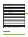
Appendices
No. Title
Type
1 BOSCH Drive Unit Performance I Intuvia |PowerPack 400 Original instructions
Charger
2 GATES CARBON DRIVE
Manual
Manual for the system belt
Attachments
No.
A
B
C
D
E
F
Document
Handover checklist
GRACE MX II Pedelec service manual
NuVinci N360
Avid (SRAM)
RockShox Sektor / RockShox Domain (SRAM)
SRAM X9 derailleur system
Page | 86
GRACE MX II Operating instructions
Technical manual
Technical manual
Technical manual
Technical manual
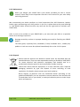
Explanations of symbols
To begin with, we would like to acquaint you with the meaning of the attention and hazard
symbols which you can find in these operating instructions.
It is very important that you follow the information by the symbols.
Caution!
This caution symbol points out a potentially hazardous situation through which
persons in the environment may sustain injury, or the product or objects may be
damaged.
Danger!
Denotes an immediate danger through explosion, for instance by improper handling
of the battery and charger.
Information!
This sign has useful information about how to handle your product.
Note!
This symbol points out that damage is possible on the vehicle.
Read the original operating manual!
This symbol refers to important information in the original operating instructions of
the component manufacturers.
GRACE MX II Operating instructions
Page | 87
1.
Your GRACE MX II
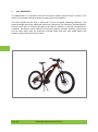
The GRACE MX II is a member of the class of electric power assisted cycles, or EPAC's. The
motor only provides assistance when you apply force to the pedals.
The force applied by the rider is measured in terms of speed, pedalling frequency, and
torque through which the motorised assistance is adjusted. The maximum assisted speed is
25 km/h (15.5 mph) or 32 km/h (20 mph) in the USA as a Pedelec, or 45 km/h (28 mph) as an
S-Pedelec. The electric motor switches off once this speed is reached. However, you are also
free to travel faster than the maximum assisted speed with your own pedal power and
without support from the electric motor.
1.
Page | 88
GRACE MX II Operating instructions
1.1. About this operating manual
This operating manual is solely for the GRACE MX II range in the Pedelec- and S-Pedelec
variants and frame sizes M and L for model year 2014. Follow the instructions and warnings
for your own safety. Failing to do so may damage the bike and/or lead to personal injury,
For maintenance work and repairs, please talk directly to your dealer.
Also observe the important information in the original operating instructions of the
component manufacturers available online:
Avid
Bosch
Busch + Müller
Cane Creek
Gates Carbon Drive
NuVinci
SRAM
RockShox
www.sram.com/de/avid
www.bosch-ebike.de
www.bumm.de
www.canecreek.com
www.carbondrivesystems.com
www.nuvinci.info
www.sram.com
www.sram.com/de/rockshox
1.2. Scope of supply
The GRACE MX II is delivered with:
•
•
•
•
•
•
•
•
•
Bosch charger
Transport safety mechanisms, x 2 for the braking system
Keys x 2 for securing the battery pack
GRACE MX II Manual
GRACE MX II Service manual
Reflectors 2 x (S-Pedelec only)
Rear-view mirror (S-Pedelec only)
Pedal reflectors, 2 pairs
Instructions for the add-on components
The following components from the scope of supply do not come assembled at delivery as
standard. However, they can be pre-assembled to the vehicle if so required. Please contact
your GRACE dealer for more information.
•
•
Mudguard:
Luggage rack:
Curana C-Lite 26'' x 60 mm (MX II Urban only)
Tubus Vega (MX II Urban only)
GRACE MX II Operating instructions
Page | 89
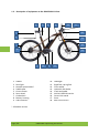
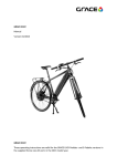
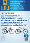
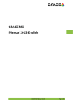
1.3. Description of equipment on the GRACE MX II Urban
1
4
8
9
18
10
2
3
11
3
12
15
13
7
1
2
3
4
5
6
7
8
9
17
Saddle
Rear light
Number plate holder*
Saddle post
Centre motor
Rear wheel
Carbon belt
Battery housing
Side reflector*
16
5
14
10
11
12
13
14
15
16
17
18
Headlight
Rigid fork, spring fork
Front wheel
Hydraulic disk brake
Crank and pedal
NuVinci N360 drivetrain
Centre kick stand
Stem
Rear-view mirror*
* S-Pedelec version
Page | 90
GRACE MX II Operating instructions
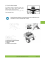
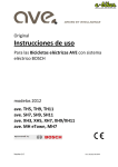
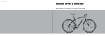
1.4. Description of equipment on the GRACE MX II Trail
1
4
8
9
18
10
2
3
11
3
12
15
13
7
1
2
3
4
5
6
7
8
9
17
Saddle
Rear light
Number plate holder*
Saddle post
Centre motor
Rear wheel
Chain
Battery housing
Side reflector*
16
5
14
10
11
12
13
14
15
16
17
18
Headlight
Spring fork
Front wheel
Hydraulic disk brake
Crank and pedal
SRAM derailleur system
Side stand
Stem
Rear-view mirror*
* S-Pedelec version
GRACE MX II Operating instructions
Page | 91
1.5. Anti-tamper plate
The anti-tamper plate is located on the down tube
under the battery. To see it, the battery will need to
be removed.
1.6. Serial number
The serial number of your GRACE MX II is located on the down tube at the height of the motor.
Please take a note of this serial number and keep it in a safe place.
1.7. Use of the vehicle as intended
The GRACE MX II Pedelec is a member of the class of electric power assisted cycles, or EPAC's.
The motor only provides assistance when you apply force to the pedals.
The GRACE MX II S-Pedelec is a moped as opposed to a bicycle and as such is subject to local
road traffic regulations (In Germany this is the German Road Traffic Regulations, StVZO). For this
reason, the vehicle does not bear a CE mark as a motorbike would but a number plate as well as
a chassis number registered with the Federal Motor Transport Authority in Germany. Please
refer to the current version of the German traffic regulations StVZO from 1st June 2010 for
information about guidelines, the equipment on mopeds for use on public roads.
Please pay attention to the following data when using the vehicle:
•
•
•
•
the safety-related advice in this operating manual
the "Technical data" chapter in this operating manual
the country-specific road traffic regulations (in Germany this is the German Road
Traffic Regulations, StVO)
country-specific regulations for vehicle registrations (in Germany this is the German
Traffic Registration Regulations, StVZO)
Before using it on main roads, first practice on your new GRACE MX II in an area with little
traffic. Bear in mind that other road users may not be able to judge the high speeds you are
riding at.
Page | 92
GRACE MX II Operating instructions
The active and passive lighting equipment required under technical safety regulations are
installed in compliance with the StVZO. This technical safety equipment must be inspected
regularly and when needed must be repaired by a technician.
The assembly of the following components is mandatory for the following Pedelec
types to make the vehicle roadworthy according to the German StVZO:
•
•
•
Reflectors 2 x (S-Pedelec)
Rear-view mirror (S-Pedelec)
Pedal reflectors (Pedelec/S-Pedelec)
Modifications to your GRACE MX II which result in an increase in the motor output
and speed put your safety while riding at risk and can lead to your driver's licence
being revoked or the loss of insurance coverage.
The total weight comprising the GRACE MX II incl. rider, accessories and luggage
must not exceed the maximum permissible weight of 150 kg (330 lbs).
The GRACE MX II is not intended for persons with impaired physical, sensory or
intellectual capabilities. GRACE MX II is also not suitable for children under 14 years.
Neither manufacturer nor dealer assume any liability for any damage resulting from
use beyond what is specified in this operating manual or from non-compliance with
technical safety instructions.
A helmet must be work at all times when riding the S-Pedelecs, and the bike must
have an insurance plate. You must have an M-category driver's licence and must
carry your licence with you at all times.
Neither manufacturer nor dealer assume any liability for any damage resulting from
use beyond what is specified in this operating manual or from non-compliance with
technical safety instructions.
Riding the GRACE MX II as an S-Pedelec with a bike trailer is not permitted.
GRACE MX II is not suitable for competitions.
GRACE MX II Operating instructions
Page | 93
2.
First time use
2.1. Charging the battery
The battery is fitted to the down tube of your
GRACE MX II. The battery can be recharged at
any time either separately or while in the vehicle.
Make sure the voltage set for your charger is the
same as that of the power supply (110V or
230V).
Next, insert the plug into the socket of the
charger. Next, connect the Bosch standard
charger to the mains.
Connect the charger plug to the battery which
has been switched off. The charger display
flashes.
The battery comes partly charged. Before using,
fully charge it. The battery is fully charged when
all 5 LEDs are permanently lit.
After the battery has been fully charged, the
charging will stop automatically. Disconnect the
charger from the mains and the battery from the
charger. The battery is switched off
automatically.
The battery can be charged at any time without
affecting its service life. Interrupting the charging
does not damage the battery.
Read the information in the Bosch technical manual
Page | 94
GRACE MX II Operating instructions
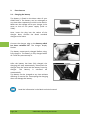
2.2. Removing the battery
Make sure the system has been switched off
before removing the battery. Turn the key in the
lock a quarter turn and at the same time, tilt the
battery to remove it out of the upper holder.
Next remove it from the lower holder.
In order to insert the battery, place it with its
contacts into the lower holder and tilt it into the
upper holder as far as it can go until the lock
audibly engages.
2.3. Important tips and advice about the battery
Only use original Bosch batteries which have been approved by the
manufacturer for the GRACE MX II. Using other batteries can lead to injuries
and the risk of fire.
If you want to stop using your GRACE MX II for a longer period of time (> 1
month), make sure that the battery is charged to approximately 60%, this is
equivalent to 3 – 4 LEDs on the display. Check the charge level after 6 months.
If only a single LED on the charge state indicator is still lit, recharge the battery
to around 60%.
The battery guarantees a minimum of 500 full charge cycles. You can extend
the life time of the battery by taking good care of it and by using it and storing
it at the right temperatures. We recommend operating temperatures
between +5 °C to +35 °C and an ambient temperature of +20 °C for storage.
Please follow the information in the original manual for the BOSCH Drive Unit
Performance | Intuvia | PowerPack 400 | Charger
GRACE MX II Operating instructions
Page | 95
2.4. Switching the system on and off
To switch the Bosch system on and off, press the
main switch on the battery.
The GRACE MX II drive can also be switched on
and of from the on-board computer.
The display on the on-board computer is also
switched on with the battery.
The on-board computer shows the charge state
of the battery as well as the settings of the drive
unit.
When switching on the bike, there must not be any load on the pedals on your
GRACE MX II - otherwise, performance of the drive may be impaired. If the
GRACE MX II was switched off accidentally while there was a load on the
pedals, switch off the bike again and switch it back on without a load on the
pedals.
The drive is activated as soon as you press down on the pedals. The level of assistance
provided is based on the settings in the on-board computer. Once you stop pressing down
on the pedals while riding, or once you have reached a speed of 25 km/h or 45 km/h*, the
drive will de-activate assistance mode.
Assistance mode is re-activated automatically
once you press down onto the pedals and the
speed is less than 25 km/h/45 km/h*. To switch
off the drive system, switch off the battery using
the On/Off button or press the On/Off button on
the on-board computer. If the drive is not used
for around 10 mins, the drive will switch itself off
automatically to save energy.
* MX II S-Pedelec
Page | 96
GRACE MX II Operating instructions
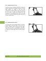
2.5. Adjusting the saddle
To adjust the height of the saddle, undo the SW5
hexagon socket in the clamp on the saddle post.
Adjust the height of the seat to your height by
placing your heel on the pedal when the crank is
at the lowest point. Your leg should almost fully
extended.
Do not extend the saddle post further than the
minimum depth mark.
Tighten the screw on the saddle post clamp (see
torque table).
If you pull out the saddle post too far, the seat tube may no longer be able to
support the saddle post sufficiently. The saddle post may come undone while
riding or it may damage or break off the seat tube. Danger of injury or
accident!
GRACE MX II Operating instructions
Page | 97
2.6. Adjusting the saddle angle
To change the angle and horizontal position of
the saddle, undo the two SW6 hexagon sockets
on the saddle clamp which are positioned
immediately behind the saddle post above the
rear wheel.
You can now move the saddle forwards and
backwards in the guide and adjust the angle.
Afterwards, retighten both screws again (see
torque table).
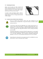
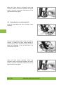
2.7. Adjusting the position of the brake lever
Undo the screw on the handlebar clamp with a Torx T25 spanner to twist and move the
brake lever on the handlebar. After adjustment, re-tighten the screw again (see torque
table).
The brake levers are configured correctly when your fingers can reach the
brake levers when your arms are outstretched. The wrist should be stretched
out as much as possible.
Page | 98
GRACE MX II Operating instructions
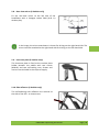
2.8. Rear-view mirror (S-Pedelec only)
Fix the rear-view mirror to the left side of the
handlebars with a hexagon socket SW4 (0.16 in)
without play.
In the image, the mirror attachment is shown for driving on the right-hand side. The
mirror must be attached to the right hand side for driving on the left-hand side.
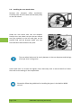
2.9. Insurance plate (S-Pedelec only)
The insurance plate is fixed to the number plate
holder beneath the saddle with two screws
(M4x10) and two self-sealing nuts. Screws and
nuts are not included in the scope of supply.
2.10. Side reflectors (S-Pedelec only)
The self-adhering side reflectors are secured to
the side of the fork - as shown next.
GRACE MX II Operating instructions
Page | 99
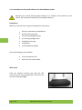
2.11. Assembly manual, pedal reflectors for Schindelhauer pedals
Operating the vehicle without pedal reflectors is a violation of the StVZO. For this
reason, we recommend assembly of the pedal reflectors.
Preparation
Make sure that all of the required components are present:
•
•
•
•
•
•
•
8x cross recessed screw M4x22mm
8x self-locking nuts M4
4x mounting wedge outside
4x mounting wedge inside
4x Reflector housing
4x Reflector
2x Schindelhauer pedals
Have the following tools available:
•
•
Cross screwdriver PH2
Wrench 7mm mouth width
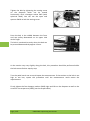
Work steps
Take the reflector housing and plug the M4
screws into the existing long holes. Then push on
this the mounting wedge.
Page | 100
GRACE MX II Operating instructions
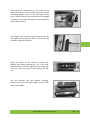
Now place the components on the front of the
pedals and push it from behind with the second
mounting wedge. Then set the M4 nuts on the
bolts. Please note that the inclination of the wedge
is placed in a way that the reflector is perpendicular
to the pedal surface.
Now tighten the screws using the above tool. Do
not tighten the screws too firmly. You should still
be able to align the reflector.
Align the centre of the reflector housing and
tighten the screws permanently. Tip: If you hold
the screwdriver still while tightening the screw and
only turn with the wrench, the housing will slip
less.
Clip the reflector into the reflector housing.
Repeat the process for both pedals and on both
sides of the pedals
GRACE MX II Operating instructions
Page | 101
3.
Before each ride
3.1. Checking the wheels and tyres
Before each ride, check:
•
•
•
The tyres and wheels for damage and any lodged foreign matter. Damaged wheels
can lead to a loss of tyre pressure and other damage.
The treads on the tyres.
The concentricity of the wheels by allowing both wheels to spin freely. Poor
concentricity may be caused by damaged tyres, broken axles or loose or broken
spokes. Explore the origin of any rattling noises and where necessary check the
bearings and screw connections.
The GRACE MX II comes with the following tyres as standard:
•
•
Schwalbe Big Ben RaceGuard 60-559 (MX II Urban)
CONTINENTAL MountainKing 2.2 (MX II Trail)
Observe the tyre pressure information provided by the manufacturer which is
printed on the tyre wall! Exceeding the maximum permissible air pressure when
pumping up the tyres can cause the tyre to puncture!
Note for S-Pedelec variant only: When replacing, make sure that only the tyres
shown below and that tyres must be assembled with a ECE-R75 release. The wheel
circumference can be adjusted via a setting function on the on-board computer.
Other tyres are also allowed by the manufacturer:
•
•
•
•
•
•
X-King 2.4 Protection C275 b/b, skw, fb - size: 60-559
X-King 2.2 Protection C275 b/b, skw, fb - size: 55-559
MountainKing 2.4 Protection C287 b/b, skw, fb - size: 60-559
RaceKing 2.2 Protection C256 b/b, skw, fb - size: 55-599
Contact II C269 b/b reflex, wire - size: 47-559
Cruise Contact C269 b/b, wire- size: 50-599
Page | 102
GRACE MX II Operating instructions
3.2. Checking the battery fitting
Before each ride, check that the battery lock cylinder is latched into position. If the battery is
not locked into place via the lock, it may dislodge during the ride and fall off.
3.3. Checking the drive
Inadequately secured belt pulleys and guides may dislodge during the ride.
Incorrectly adjusted drive belts may drift out of the pulleys while riding the bike.
Risk of accident and injury!
Always follow all instructions concerning how to work with drive belts, especially
when installing or removing the rear wheel. Extra care is needed to prevent damage
to the drive belt.
Before each ride, check
•
•
whether the drive belt is properly aligned and taught and the belt pulleys are firmly
screwed on.
that the belt guide is correctly installed to prevent the drive belt from skipping and
leaving the rear belt pulley.
3.4. Checking the function and wear of the brake system
On disc brakes, the pressure point must be stable. When the pressure point is not reached
after two thirds of the way, pull the lever several times ("pumps") until the linings rest
against the disk. When the pressure point wanders during the ride, the braking system must
vented in a specialist workshop.
Before each ride, carry out a brake check while the bike is stationary. To do so, pull the
braking lever towards the handlebars with two fingers and normal braking force. The brake
lever must not touch the handlebar grip.
Brake discs, brake callipers, and quick-release clamps and axle nuts can become
very hot after braking, especially on longer rides. Danger of injury!
Check the braking discs:
•
•
You should not be able to see any grooves or brake-outs with the naked eye. The
friction surface must be free of oil and dirt.
All screws must pre present and have a firm fit.
Check the brake callipers for oil leaks. Make sure the brake cables are kink-free. Check the
seal on the brake cables.
GRACE MX II Operating instructions
Page | 103
Pressure point: Each brake has a certain amount of idle motion at the brake lever.
When this idle motion is overcome with a small amount of handforce the brake will
apply, the pressure point is reached. If the brake is properly adjusted and vented,
applying a greater handforce will result in a higher braking performance while
moving the brake lever a shorter distance.
Brake pads and discs wear due to friction. The more often you ride in a hilly
environment or through rain or dirt, the higher the wear.
The braking system on the GRACE MX II has a fully-automatic pad synchronisation
system. This system balances the wear on the brake pads so that the pressure point
of the brake is always constant.
The wear condition of the brake pads can be checked with the transport securing
mechanism. The pads are worn and must be replaced when the thick end of the
transport securing mechanism no longer fits between the lugs on the brake pads
while the brake is applied.
New brake pads must be run in until they reach their optimal braking performance.
Accelerate the bike approx. 30-50 times to around 20 km/h (19 mph) and brake
until the bike comes to a stop. If the necessary handforce stops falling to brake, the
run-in procedure is closed.
3.5. Checking the spring fork (RockShox Domain, RockShox Sektor)
Before each ride, clean dirt and contaminants on the upper tubes and check them for
scratches.
Lubricate the seals and tubes before each ride.
3.6. Checking the screw connections
Before each ride, check whether the following screw connections are tightened firmly:
•
•
•
•
Securing the front wheel
Securing the rear wheel
Securing the grips and brake levers. It must not be possible to twist them.
Securing saddle and saddle post
Page | 104
GRACE MX II Operating instructions
3.7. Lights
Before each journey, make sure that the lights are
working. Make sure that the headlamp range on
the headlight is adjusted to meet local national
regulations. Correctly adjust the headlamp range
of the light. Observe Chapter 4.7.
4.
Function description
4.1. NuVinci N360 shifter Urban
On the NuVinci N360 rear wheel hub, the gear
ratio is easily adjusted by pressing the shifter.
The gear ratio appears on the shifter display as
an easy-to-understand graphic - a hill for driving
more slowly and a plain for quicker speeds.
There are no fixed gears so you can adjust the
gear ratio freely.
4.2. NuVinci N360 rear wheel hub Urban
Gera shifts take place inside the hub – soft and
comfortably by means of maintenance-free shift
elements which the hub protects from the
elements.
GRACE MX II Operating instructions
Page | 105
To preserve the longevity of the NuVinci hub and the shifter, we recommend you
only shift gears when there is a reduced load on the pedal.
Avoid shifting under full load and shifting against increased resistance when
activating the shifter.
Read the information in the NuVinci N360 technical manual
4.3. Gear SRAM X9 Trail
The shifting process in the SRAM X9 derailleur
system is carried out by activating the switch on
the right handlebar grip.
Note:
To preserve the service life of your X9 derailleur
system, we recommend you do not activate it
while stationary and only when there is a reduced
load on the pedal. Do not shift under full load.
Read the information in the SRAM X9 technical manual
4.4. Motor Bosch Drive Unit
The drive system has three sensors (speed, pedal
frequency and torque applied by the driver) in
order to optimally support the current driving
situation.
Page | 106
GRACE MX II Operating instructions
4.5. Bosch on-board computer
The display provides information about the:
Support level, speed, range, average speed,
maximum speed, distance and time.
You can choose between four drive types: Eco,
Tour, Sport and Turbo.
Please follow the information in the original manual for the BOSCH Drive Unit
Performance | Intuvia | PowerPack 400 | Charger
a.
b.
c.
d.
e.
f.
1.
2.
3.
4.
5.
6.
7.
8.
Engine output display
Assistance level display
Text display
Number display
Tachometer display
Battery charge state indicator
Display function "i" button
Lighting button
On-board computer
On-board computer holder
On/Off button on-board computer
Reset button "Reset"
USB port
Protective cap for USB port
GRACE MX II Operating instructions
Page | 107
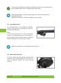
4.6. Bosch control unit
10. Control unit
11. Display function "i" button on the control
unit
12. Lower value/scroll down button "–"
13. Increase value/scroll up button "+"
14. Push assistance button "WALK"
3.
4.
15.
16.
On-board computer
On-board computer holder
Lock-latch for on-board computer
Locking screw for on-board computer
(included in delivery)
17. Speed sensor
18. Spoke magnet of the speed
sensor
Page | 108
GRACE MX II Operating instructions
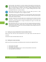
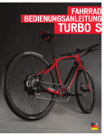
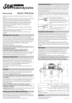
4.7. Lights
A precise lens system scatters light of a highperformance LED evenly on the road surface. This
produces a high light intensity thus increasing
safety.
Pressing the lighting button on the on-board
computer switches on the LED headlight and the
rear light.
The headlamp range must be adjusted according
to local national regulations. The adjacent figure
shows the requirements as applicable for
Germany for example. The headlight must be
adjusted so that the light cone hits the ground
after 10 m, or at distance of 5 m (16.4 ft) is only
half as high as when it was emitted.
a/2
10 m
a
5m
Park the bike on an even surface. Undo the
screw underneath the headlight with an Allen
key SW 3 and tilt it accordingly.
GRACE MX II Operating instructions
Page | 109
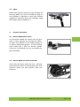
4.8. RockShox Sektor RL Trail
A lockout function disables the fork's suspension
function to allow you to pedal efficiently on a level
road surface. To enable it, turn the blue
"Compression" setting head on the fork crown to
the right as far as it goes. The black setting head
can be used to adjust the stiffness of the
suspension. The right-hand fork has a red knob
which can be used to adjust the speed with which
the fork springs down.
4.9. RockShox Domain Urban
The spring fork has two setting options. The blue
setting head on the top right, as seen from the
driver's viewpoint, can be used to set the speed
with which the fork is compressed. The lower
right-hand fork has a red knob which can be used
to adjust the speed with which the fork springs
down.
Page | 110
GRACE MX II Operating instructions
5.
Maintenance
5.1. Before every maintenance
Any time before conducting any
maintenance work, make sure the
drive is switched off.
Respect the information in the original BOSCH user manual
5.2. Removing the front wheel spring fork
Undo the quick release on the axle of the front
wheel. Firstly turn the lever 180° and then
engage it into the recess of the axle. The axle can
now be unscrewed with the aid of the lever.
Pull the quick-release axle out of the fork by
moving it towards the right. While doing so,
firmly hold the front wheel and undo the front
wheel by removing it out of the fork in a
downwards direction.
GRACE MX II Operating instructions
Page | 111
When the front wheel is removed, insert the
transport safety mechanism between the brake
pads to prevent unintended adjustment of the
gaps between brake pads.
5.3. Removing the front wheel rigid fork
Undo the quick-release axle with a hexagon socket
SW14mm.
Pull the quick-release axle out of the fork by
moving it towards the right. While doing so,
firmly hold the front wheel and undo the front
wheel by removing it out of the fork in a
downwards direction.
With the front wheel removed, insert the
transport safety mechanism between the brake
pads to prevent unintended adjustment of the
gaps between brake pads.
Page | 112
GRACE MX II Operating instructions
5.4. Removing the rear wheel Urban
The rear wheel can be removed from the dropout
by undoing the axle nuts SW15. Carefully slide the
drive belt past the belt pulley.
With the rear wheel removed, insert the transport
safety mechanism between the brake pads to
prevent unintended adjustment of the gaps
between brake pads.
Please also follow the guidelines in the NuVinci N360 manual
5.5. Removing the rear wheel Trail
Using the safety button attached to the derailleur,
lock the derailleur to relieve the tension on the
chain. Next, undo the quick release and guide the
rear wheel out of the dropouts by moving it
downwards.
Insert the transport safety mechanism between
the brake pads to prevent unintended adjustment
of the gaps between brake pads.
GRACE MX II Operating instructions
Page | 113
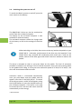
5.6. Installing the rear wheel Urban
Remove the transport safety mechanism.
Carefully place the drive belt onto the belt pulley
on the rear wheel.
Guide the rear wheel axle into the dropout.
Position the rear wheel so that the two torque
arm (key washer) on the left and right on the
outside slide into the dropout. Make sure that
the brake disc slides between the pads.
The rear wheel axle must lie evenly between in the two dropouts and the lugs
of torque arms in the groove .
Attach both axle nut screws and tighten them alternately with a wrench SW15 to 30 Nm.
Also refer to the settings in the torque table.
Please also follow the guidelines for installing the gears in the NuVinci N360
manual
Page | 114
GRACE MX II Operating instructions
5.7. Installing the rear wheel Trail
Remove the transport safety mechanism. Guide
the rear wheel axle into the dropout. Make sure
that the brake disc slides between the brake
pads. Fix the rear wheel with the quick release at
the rear. Undo the lock-latch of the derailleur so
that the chain is retightened.
5.8. Tensioning and aligning the drive belt Urban
The drive belt Gates Carbon Drive is very strong and enduring. However, before and during
assembly, show the utmost care to prevent damage to the carbon fibres which constitute
the actual strength of the drive belt. Extreme bending and rotating causes cracks which can
lead to faults to the belt under higher loads.
Please follow the guide about working with the belt on the Gates Carbon
Drive system and the user manual for the Gates Carbon Drive.
When the tension on the drive belt is set too low, this can cause the drive belt
to slip through on the timing pulleys.
This may cause damage to the carbon fibres inside the drive belt. If the drive
belt has slipped, you must have it replaced by a specialist workshop.
If the tension on the drive belt is too high, this may cause damage to the
bearings and seals in the wheel hub. This also increases the wear and
frictional losses in the entire drive.
Undo the four hexagon sockets (SW6) right and left on the dropouts as well as the screw for
the torque arm (SW5).
GRACE MX II Operating instructions
Page | 115
Tighten the belt by tightening the setting screw
on the dropouts which can be moved
horizontally, with a hexagon socket SW5 (with
spherical head). You can use the open end
spanner SW10 to lock the setting screw.
Press the belt in the middle between the front
and rear pulley downwards on its upper side
with a finger.
The belt is tensioned correctly when the belt can
be pressed downwards by approx. 12mm.
As the tension may vary slightly along the belt, this procedure should be performed while
the belt moves further step by step.
Turn the pedal crank one turn and repeat the measurement. If the tension on the belt is too
high or too low, repeat this procedure until the measurement result meets the
requirements.
Firmly tighten the four hexagon sockets (SW6) right and left on the dropouts as well as the
screw for the torque arm (SW5) (see the torque table).
Page | 116
GRACE MX II Operating instructions
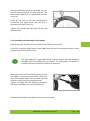
5.9. Setting the belt guide Urban
The gap A between the belt guide and the back
of the belt should lie between 1 - 1.5 mm (0.04 0.06 in). To adjust the gap undo the screw with a
hexagon socket SW5 (0.2 in) and move the belt
guide in the elongated bore.
Tighten the screw again with a hexagon socket SW5
(0.2 in) (see torque table).
A
5.10. Drive chain Trail
The chain should always be metallically clean and have a sufficient coating of lubricant.
If the chain is dry (without lubrication) or dirty, clean it with a clean or slightly oily cloth and
then coat it with a standard, commercially available bicycle chain oil and leave it overnight.
Remove any excess oil the following day with a cloth.
5.11. Switching gears Trail
For information about the gearshift adjustment,
please refer to the attached manual from
manufacturer SRAM
GRACE MX II Operating instructions
Page | 117
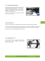
5.12. Tyre change
Remove the valve cap on the tube and, where
present, the knurled nuts on the valve connection.
Remove the air from the tube by pressing the
valve pin. Using a tyre lever, remove the tyre from
the rim. Replace faulty tyres or tubes.
Always replace the tube when replacing an existing tyre with a new tyre!
Pull the tyre with one side onto the rim. Pay
attention to the tyre direction stamped onto the
tyre by the manufacturer.
Push the valve through the hole and place the
tube into the rim well.
Page | 118
GRACE MX II Operating instructions
Using the assembly aid, lever the wheel rim over
the rim flange. Pump up the tube until the tyre
takes shape. Make sure it is positioned correctly
in the rim.
Pump up the tyre as per the manufacturer's
instructions and again check that the tyre is
positioned correctly in the rim.
Tighten the knurled nuts and screw the valve cap
onto the valve.
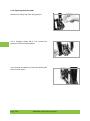
5.13. Assembly and disassembly of the pedals
Apply a thin layer of grease to the threads on the pedal axis and crank.
First of all, screw the pedal loose by hand. Make sure the parts are positioned at the correct
angle to each other and do not tilt.
The right pedal has a right-hand thread, the left pedal a left-hand thread to
the pedal axle for assembly onto the cranks. The right pedal is screwed in a
clockwise direction and the left pedal anti-clockwise.
Move the crank into a horizontal position so that
the pedal is facing the front wheel. Place the
open end spanner SW15 on the pedal axle and
hold the crank firmly on the opposite side.
Tighten the pedal with the torque according to
the data provided by the crank manufacturer.
Disassembly proceeds in the opposite direction to assembly.
GRACE MX II Operating instructions
Page | 119
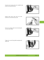
5.14. Replacing the brake pads
Remove the safety clip from the guide pin.
Use a hexagon socket SW 2.5 to remove the
guide pin from the brake calliper.
Use a slotted screwdriver to press the brake pads
back into the piston.
Page | 120
GRACE MX II Operating instructions
Remove the H springs with the installed brake
pads out of the brake calliper.
Replace both brake pads when the total
thickness is less than 3mm per pad.
Place the H springs with the new brake pads
into the brake calliper.
Tighten the screw fitting before applying the
safety clip.
GRACE MX II Operating instructions
Page | 121
6.
Transport
To prevent damage to your GRACE MX II during transport, please heed the following
instructions:
Before transporting on a car roof or tailgate carrier, do not remove firmly-fixed accessories
such as the display unit.
Slide the transport safeties into the brake callipers provided that you dismantle the wheels.
Transporting the GRACE MX II battery in a passenger aeroplane is not
permitted.
Transporting the GRACE MX II with its battery installed on a car with a roof or
tailgate carrier is not permitted. Remove the battery before transport.
The weight of the bike places special requirements on a car roof or tailgate
support. Unsuitable vehicle supports can rupture while riding or may not be
able to support the GRACE MX II reliably.
Only use suitable bike carriers for the transport. Take notice of the information
given in the vehicle manual on roof loads and bearing loads as well as the
instructions in the assembly/operating manual for the bike carrier.
7.
Cleaning and maintenance
Do not use high-pressure cleaners to clean the GRACE MX II. The strong water
jet from a high-pressure cleaner can cause damage to tyres, drive belts,
bearings or electric components which are not visible externally. Components
damaged in such a way may fail unexpectedly. Risk of accident!
In particular, take the following instructions into account when maintaining
your GRACE MX II:
Use as little water as possible and keep it away from electrical contacts. Clean
the vehicle with a soft sponge or soft brush. Clean the battery carrier on the
down tube with a damp cloth. Allow the electrical plug connections to dry
before putting the bike back into operation.
Page | 122
GRACE MX II Operating instructions
8.
Wear parts, maintenance, vehicle inspection after an accident
Some parts and components on your GRACE MX II are susceptible to function-related wear.
For this reason, such parts need to be monitored very closely and regularly maintained or
replaced.
The wear parts include:
8.1. Tyres
Tyres wear according to how the GRACE MX II is used and can vary considerably from one
rider to the next. Heavy braking which causes the wheel to lock up reduces the service life of
the tyre considerably. The tyre pressure should be checked regularly and the tyres must be
inflated to the value indicated by the tyre manufacturer.
8.2. Brake pads
The brake pads are subject to function-related wear which is heavily dependent on how the
GRACE MX II is used. When riding along tracks with heavy drops or when using it for bike
sports, it may be necessary to replace the brake pads at shorter intervals. It is therefore
essential that you check the wear on your brake pads regularly. When necessary, have them
replaced by a specialist dealer.
8.3. Belt
Always replace the Gates carbon drive belt when damaged due to improper handling or
serious external influences. For instance, when a stone, twig or piece of clothing is caught in
the belt and drawn between the belt and the belt pulleys. This kind of external influence can
cause damage to the sensitive carbon fibres inside the belt even if there does not appear to
be any damage to the belt on the outside. If you suspect the belt may be damaged, replace it
as a preventative measure against accident or injury.
GRACE MX II Operating instructions
Page | 123
8.4. Replacing the belt pulleys when they are damaged
The belt pulleys must be replaced if they are damaged by serious external influences. For
instance, if you land hard with the front belt pulley when riding over a rock or twig, it may
bend, and in this case will need to be replaced. Stones which are drawn in and get in
between the belt and belt pulleys can damage the teeth on the belt and may even damage
or tear off some of them. The affected belt pulley will need to be replaced in this case as
well. Whether or not you will also need to have the belt replaced will depend on the criteria
in the previous section. If there is wear on the drive and all components were in use for the
same time, we generally recommend you replace all components even if only one of the
components has reached its wear limit.
8.5. Chain Trail
The chain is susceptible to function-related wear which depends on maintenance, repair and
the how the GRACE MX II is used (performance, dirt, salt, riding in rain, etc.). The service life
can be extended by regularly cleaning and lubrication. However, the chain will need to be
replaced when it reaches its wear limit.
8.6. Chain wheels, cartridge, rear derailleur rollers and the bottom bracket Trail
All sprockets, chain wheels and the bottom bracket are susceptible to wear due to their
function. The wear on these components depends on maintenance, repair and the how the
GRACE MX II is used (performance, dirt, salt, riding in rain, etc.).
8.7. Shift cables
The Bowden cables on the gears must be regularly maintained and may need to be replaced.
In particular, this can be case when GRACE MX II is often left outdoors and exposed to the
elements.
Page | 124
GRACE MX II Operating instructions
8.8. Handlebar grips
Handlebar and grip surfaces are subject to function-related wear and may need to be
replaced at regular intervals. The grips must always be firmly attached to the handlebars.
8.9. Lubricants
Lubricants change their properties in time. For this reason you should regularly clean and relubricate all lube points to prevent increased wear on the affected parts and bearings.
8.10. Handlebars and saddle post
Both the handlebars and the saddle post are subject to strong dynamic loads while riding.
Therefore, check them at regular intervals for externally visible damage, replace when
necessary. We also recommend you replace these parts every two years with heavy use of
the GRACE MX II.
8.11. Moving parts and bearings
All moving parts and bearings are subject to use-related wear. The degree of wear depends
on how the bike is maintained, services and how it is used (distance, riding in rain, dirt, salt).
8.12. Frame paint and coating
The coatings on the parts of your GRACE MX II protects them from corrosion. Regularly
check all paint surfaces for damage and touch up these surfaces right away. This also
preserves the look of your bike.
GRACE MX II Operating instructions
Page | 125
8.13. Maintenance
When you bought your GRACE MX II your dealer provided you with a service
manual. Please keep to the inspection intervals in the manual for your own safety
and riding pleasure!
We recommend your dealer performs an initial inspection after 100 kilometres. Spokes,
brakes, gears and bearings may shift position in this run in phase due to the parts breaking
in. Your GRACE dealer knows your bike very well and has the right tools to maintain your
GRACE bike.
After a crash or an accident on your GRACE MX II, you must take your bike to a specialist
dealer for a thorough inspection.
Damage caused by crashes or improper handling must only be fixed by your GRACE
dealer!
The faulty parts, especially forks, handlebars, frame, handlebar stem , saddle post,
pedals or crank arms must be replaced immediately due to the risk of rupture.
8.14. Disposal
Waste electrical devices and batteries should never be discarded with the
household waste! They must be separated according to Guideline 2002/96 EC
for waste electrical and electronic equipment and handed over to a
professional collection point for environmentally friendly recycling.
Please take waste electrical equipment at a local collection point. Separate
packaging materials by type and dispose of them according to local
regulations. For details, please contact your local authority.
Never dispose of batteries with the household waste! According to the
guideline 2006/66/EC you are required to remove batteries from the bike and
to hand them over to your dealer, a municipal collection point or other shops
which sell batteries.
Page | 126
GRACE MX II Operating instructions
9. Technical data GRACE MX II Urban
Frame
Forks
Motor
Torque
Batteries
Display
Forks bearing
Braking
Drive
Tyres
Charger
Weight
Special features
Range
Saddle post
Handlebars
Handlebar grips
Stem
Saddle
Alloys
Front wheel hub
Rear wheel hub
Pedals
Controller
Cranks
Permissible
total weight
Frame sizes
Charge time
Headlight
Rear light
Aluminium 6061
Rigid fork 26“ Unicrown / RockShox Domain RC
Bosch Drive Unit Performance 250 Watt/ Bosch Drive Unit 350 Watt
max. 48 Nm
Bosch Li-Ion 36V/11Ah 400 Wh
Bosch 4-Mode LCD display, background lighting
Cane Creek 40 series
Avid Elixir 5, 200mm (front) and 180mm (back)
Gates Carbon Drive with NuVinci N360 hub
Schwalbe Big Ben RaceGuard 60-559
Bosch Charger 4 Ah/42V
24.1 kg
4 drive modes (Eco, Tour, Sport, Turbo)
max. 175 km* / max. 120 km**
Truvativ Stylo
BikeLink 710mm
Velo
Truvativ Stylo
Ergon SM30 MTB
Rigida Taurus 21
KT Industries
NuVinci N360 hub
Schindelhauer
Bosch HMI unit
Lasko
150 kg
Size M or L
Approx. 3.5 hours
Busch & Müller Lumotec Lyt 42
DToplight Mini LED* SHINYO LED rear light (E-marked)**
** MX II S-Pedelec
* MX II Pedelec
GRACE MX II Operating instructions
Page | 127
10. Technical data GRACE MX II Trail
Frame
Fork
Motor
Torque
Batteries
Display
Forks bearing
Braking
Drive
Tyres
Charger
Weight
Special features
Range
Saddle post
Handlebars
Handlebar grips
Stem
Saddle
Alloys
Front wheel hub
Rear wheel hub
Pedals
Controller
Cranks
Permissible
total weight
Frame sizes
Charge time
Headlight
Rear light
Aluminium 6061
RockShox Sektor Gold 140 mm RL
Bosch Drive Unit Performance 250 Watt/ Bosch Drive Unit 350 Watt
max. 48 Nm
Bosch Li-Ion 36V/11Ah 400 Wh
Bosch 4-Mode LCD display, background lighting
Cane Creek 40 series
Avid Elixir 5, 200mm (front) and 180mm (back)
SRAM X9 derailleur system
Continental Mountain King 2.2, 26"
Bosch Charger 4 Ah/42V
21.9 kg
4 drive modes (Eco, Tour, Sport, Turbo)
max. 175 km* / max. 120 km**
Truvativ Stylo
BikeLink 710mm
Velo
Truvativ Stylo
Ergon SM30 MTB
Rigida Taurus 21
SRAM X9 15*100
SRAM X9
Wellgo
Bosch HMI unit
Lasko
150 kg
Size M or L
Approx. 3.5 hours
Busch & Müller Lumotec Lyt 42
DToplight Mini LED* SHINYO LED rear light (E-marked)**
** MX II S-Pedelec
* MX II
Pedelec
Page | 128
GRACE MX II Operating instructions
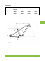
11. Frame sizes
GRACE MX II
Size M
GRACE MX II
Size L
A
Top tube
B
Standover
height
C
Inside leg
measurement
D
Seat tube
height
588mm
790mm
559mm
420mm
622mm
790mm
675mm
500mm
GRACE MX II Operating instructions
Page | 129
12. Torques
Torques for connecting elements of wheels
Rear wheel axle nuts
Dropout on frame (M8)
Torque arm, left dropout
30 Nm
16 Nm
6 Nm
Torques for handlebars and stem
Stem handlebars
Stem forks
Gripshift
Brake lever
5 Nm
5 Nm
2 – 2.5 Nm (data from NuVinci)
2.8 – 3.4 Nm (data from SRAM)
Torques for add-on parts
Brake callipers
Screw fitting for brake pads
Post-mount adapter
Saddle clamp
Saddle fixing
Brake disks
8 – 10 Nm (data from SRAM)
1 Nm
9 – 10 Nm (data from SRAM)
8 Nm
10 Nm
6.2 Nm (data from SRAM)
Page | 130
GRACE MX II Operating instructions
13. Warranty
A statutory warranty period of two years has been in effect since 01/01/2002. The warranty
period begins when you receive your GRACE MX II from your dealer, who is your contact
person for all warranty issues.
Please keep the new owner's certificate and invoice or till receipt in a safe place for the
duration of the warranty period.
A warranty claim is valid under the following conditions:
•
•
•
•
If there is a manufacturing or material defect, or misinformation,
if the claimed damage already existed at the time of the handover,
if the change to the product was not the result of function-related wear or ageing, and
if the damage did not originally arise as the result of using the bike as intended,
The following is excluded from the warranty:
•
•
•
•
•
All wear parts, according to the list of wear parts under point Wear parts, maintenance,
vehicle inspection after an accident unless production or manufacturing defects are
involved;
damage arising from the use of the bike in competition;
damage arising through improper repair tools and inadequate maintenance;
repairs which was the result of the use of used parts;
damage which was the result of retrofitting non-standard equipment and technical
modifications.
When purchasing your GRACE MX II you receive these instructions as well as
with the instructions and warranty and warranty terms and conditions from
the manufacturers of add-on components.
Please carefully read through these documents as well!
GRACE MX II Operating instructions
Page | 131
14. EC Declaration of Conformity
Name/address of the manufacturer:
MIFA AG, Kyselhäuser Straße 23,
D-06526 Sangerhausen, Germany
Product name:
EPAC/Pedelec (vehicle with electric motor as auxiliary drive)
This declaration only concerns products in the condition they were placed on the market; parts added by the end user
and/or post-purchase interventions are not considered. This declaration becomes invalid when the products are converted
or modified without agreement.
MGE-014-01, MGE-014-03, MGE-014-05,
MGE-014-07, MGE-014-09, MGE-014-11,
MGE-014-13, MGE-014-15
Type:
Year of manufacture: 2014
The designated product meets the requirements of the Guidelines:
•
•
•
•
Machinery Directive 2006/42/EC
EU Directive on Electromagnetic compatibility 2004/108/EC
Electrical Equipment Directive 2003/95/EC
Directive on the restriction of certain hazardous substances in electrical and electronic equipment 2011/65/EU
Related harmonised norms and other technical norms:
DIN EN 15194:2009
DIN EN ISO 13849:2008
DIN EN 62079:2001
DIN EN 62321:2011-04
Cycles - Electrically power assisted cycles - EPAC Bicycles
Safety of machinery - Safety-related parts
Preparation of instructions for use – Structuring, content and presentation
Methods for determining certain substances in electricalproducts
The designated product meets the requirements of the Guidelines:
Product name:
Charger for charging electro-chemical energy storage devices
The Bosch charger
Type:
0 275 007 907
satisfies
relevant EU guidelines
In the event of modifications of the designated equipment we did not approve, this certificate loses its validity
Karl-Heinz Nicolai; Kyselhäuser Straße 23; D-06526 Sangerhausen
Authorised documentation representative:
Sangerhausen, 11.02.2014
(Place, date)
Page | 132
(legally binding signature of the publisher)
CEO Karl-Heinz Nicolai
GRACE MX II Operating instructions