1
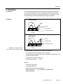
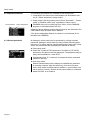
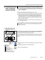
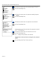
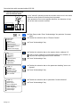
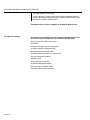
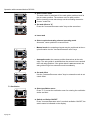
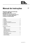
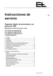
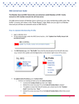
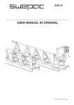
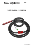
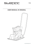
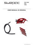
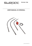
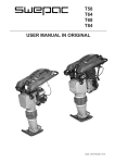
Operating manual en Digital web guider WSS Hybrid guiding (web center) with motor-driven sensor positioning device VS .... with position controller DC 03.. / DC 23.. and command device DO 200. 1. 2. 3. 4. 5. 6. 7. 8. 9. Function Assembly Installation Setup mode Commissioning with command station DO 200. Operation with command device DO 200. Optimization Maintenance Technical data Component descriptions: Sensor Sensor support beam Actuating element Command stations Digital interfaces (optional) Control card Electrical components (optional) CAN bus, serial bus Service manual (optional) Spare parts Parameter lists Diagrams 3 5 5 7 9 17 21 23 23 B C D H I J U V W X Y Z ANL--251003-EN-01 Operating instruction notes Explanation of symbols jobs to be performed important information and instructions sections of the manual due particular attention to assure the safe operation of the web guider. Operating manual structure The E+L web guider manual consists of a general system description (A), individual component descriptions (B, C, ... W), spare parts lists (X), parameter lists (Y) and diagrams (Z). Proceed according to the operating manual instructions. All important operating procedures are explained in the manual. Where necessary, reference is made to the individual component descriptions. The block diagram includes a schematic of your system. The block diagram also includes the address settings in the case of web guiders designed by E+L. See the parameter lists for explanations of the individual setup parameters. See "Setup editor" section 4 for procedure on checking/changing parameters. Type overview The operating manual applies for web guiders with the following actuating elements: - reel station WS A page 2 Function 1. Function 1.1 Purpose The web guider positions the moving web according to the web center. It corrects deviations from the set position and thus prevents it wandering off to the side. Web oscillation within the operating range of the actuating element and width measuring are possible. 1.2 Design Unwind station Sensor Support beam Actuating element Actuator Wind station Sensor Support beam Actuating element Actuator Example: web guider WSS with reel station, sensor and support beam The web guider consists of the following components: - two sensors for actual position value recording - an actuating element (steering roller reel station) with actuator and a return-to-center switch - a motor-driven support beam VS .... - a digital controller DC .... or SE ..... optional - command station DO .... - command station NT .... - web offsetting command station RE .... - digital interface DI .... (e.g. CAN-SPS, CAN-ARCNET, CAN-INTERBUS) KAP--250967-EN-01 A page 3 Function 1.3 Operating principle To insert the web move the actuating element to its center position and drive the sensors to their outer position. Once the web is inserted, drive the sensors to the web edge. If the web guider is in automatic and the guider stop contact is enabled, the web is guided. The sensors follow up in the event of web width deviations. The sensor scans the web edge. If the web edge deviates from its set position, the sensor sends the magnitude and direction of the deviation to the digital controller for evaluation. The position controller corrects the web edge back to its set position via the actuating element. 1.3.1 Oscillation The oscillating function is used to offset the web to the left/right of the set position. Use command station DO 01.. / DO 20.. or the setup parameters to set the oscillating time and stroke. With path-dependent oscillation the oscillating time and stroke can be specified by the customer (reel station controls). The web continues to be guided during oscillation. 1.3.2 Width measuring The web width is displayed in mm in conjunction with command station DO 01.. / DO 20.. or remote display DO 002. . A page 4 Assembly / Installation 2. Assembly Please observe the locally applicable and professional safety and accident prevention regulations! 2.1 Actuating element Mount actuating element according to attached description. See also dimensioned or set-up drawing. 2.2 Sensors The sensors are pre-mounted on the actuating element (sensor support beam). In exceptional cases, see sensor and actuating element descriptions, application instructions section. 2.3 Support beam (optional) The support beam is pre-mounted on the actuating element. In exceptional cases, see support beam description. The support beam must be mounted so that the sensors are located immediately after the actuating element, see also actuating element description, application instructions section. 2.4 Digital controller The digital controller is either mounted on the actuating element or designed for mounting in a control cabinet on-site. The connection between control board and D.C. positioning drive can run in one line up to a length of 3 m. However, if the distance is between 3 m and 10 m then the motor lead and the lead of the incremental encoder MUST run seprately. 2.5 Command stations (optional) 3. Installation The command stations should be mounted in such a way that the operator actually sees the equipment he is controlling (e.g. the support beam). Please observe the locally applicable and professional safety and accident prevention regultions ! Run electrical leads according to the attached wiring diagram. 3.1 Sensor No installation work is requried for compact systems. See the sensor description for exceptions. 3.2 Support beam (optional) No installation work is required for compact systems. See the description "Suppor beams" for exceptions. KAP--250504-EN-01 A page 5 Assembly / Installation A page 6 Setup mode 4. Setup mode 4.1 Basic operation in setup mode Setup settings should be performed by qualified personnel only. Basic operation in setup mode on how parameters are displayed and changed, is documented in the following diagram. In setup mode, the parameter values may be displayed and modifiable parameter values also changed by each device featured in the CAN network. Setup mode iis started via the "Acknowledge" key and, at the same time, the "Increase value" key. If a password is requested in the display, setup mode may only be started once the password has been entered . + Enter the password via the "Increase/Decrease value" keys. Press "F2" to select each individual place. + Press "Decrease value" to select the "Show Cannet" menu option. To quit setup mode you must select the "Keyboard" menu option. Then press the "Acknowledge" key. Select the required device via the "Increase/Decrease value" keys . The parameter value may be changed via the "Increase/ Decrease value" keys Select the required parameter via the "Increase/ Decrease value" keys. To change a parameter, the latter must be opened via the "Acknowledge" key . Select the required option via the "Increase/Decrease value" keys. A tick is set via the "Acknowledge" key . With round brackets () only one menu option may be selected, with square brackets [] several. KAP--250211-EN-01 A page 7 Setup mode 4.2 Important additions The following two options are available to quit setup mode: 1. Jump back in the menu to the start window (as described in section 4.1 "Basic operation in setup mode"). 2. Setup mode is quit by pressing one of three "Automatic", " Center mode" or "Manual mode" keys, regardless of where one is. Device address Device designation CANMON may only be called up once, either via the CANMON program or command station DO 200. . A flashing device address means that two devices are featured in the CAN network with the same device address. If the device designation flashes, the device is not featured (is not identified via CANMON). 4.3 Allocate password All settings in setup mode may be protected by a freely selected password. Settings in setup mode are only possible following password entry. To assure that no unauthorised persons may enter setup mode, we recommend that a password is defined as follows: Start setup mode. Select the "customer PIN" parameter in the device (*ZC 4070*) and enter a five-place numerical password. The password may be freely selected between 1 and 32767. If parameter value "0" is entered, no password will be requested (status on delivery). Quit setup mode. Should unauthorised persons attempt to establish the password by entering numbers, after the third entry of an incorrect password, setup mode is inhibited and in addition, a commentary entered in the error memory. Switch off the power briefly on command station DO 200. to re-enable it. A page 8 Commissioning with command station DO 200. 5. Commissioning with command station DO 200. There must not be anybody present in the web guider's danger area during commissioning or operation. Please observe the locally applicable and customary safety and accident prevention regulations. Check the individual connecting cables are correct. Connect all the web guider's equipment to the operating voltage. Check CAN bus connections. The light emitting diodes for the CAN bus connections on the web guider and the command stations illuminate green, i.e. ready. If a light emitting diode illuminates red, there is a malfunction on this CAN connection. Check device and CAN cabling. Position sensor, check and set if necessary (e.g. adjustment etc.), see sensor description. A prerequisite for continued commissioning is complete mechanical assembly, as well as the correct CAN addressing of the individual components. 5.1 Setting direction of web travel on the command station Direction of web travel on the overall machine HELP The direction of web travel arrow in the display on the command station must match the direction of web travel in the overall machine. This setting defines the allocation of the keys. If the arrow points in the opposite direction, the value in the parameter "arrow direction" in the command station must be inverted as follows: F1 F 2 F 3 F 4 + System-Menu Keyboard Canmon Show Cannet Rescan Cannet Save Cannet EEProm CAN Status Check Power Supply Start Setup mode. Press "Acknowledge" key and also "Increase value". Position selection bar on "Rescan Cannet". Press "Acknowledge" key. KAP--250974-EN-01 A Page 9 Commissioning with command station DO 200. CAN 0.1(FR5001) 0.2(FR5001) 0.5(RK4...) (Center Switch) 0.8(AK 4022) 0.A(*ZC4071*) 0.B(LK4203) 0.A (*ZC4071*) ZC 4071 keyboard settings width user parameter special keys 0.A (*ZC4071*) ZC 4071 keyboard settings keyboard usage arrow direction used sensor values used add. values width 0.A(*ZC4071*) arrow direction ( * ) Normal ( ) Inverted Position the selection bar on the command station "*ZC 4071*". Press "Acknowledge" key. Position the selection bar on the parameter heading "keyboard settings". Press "Acknowledge" key. Position the selection bar on the parameter "arrow direction". Press "Acknowledge" key. Invert parameter value. The actual state of the parameter is marked by a " * " in the parameter. Position the selection bar on the value that is not in use. Press "Acknowledge" key. The " * " changes to the parameter value selected. The direction of web travel has been changed on the command station. Leave Setup mode. Press "Center mode" key. A Page 10 Commissioning with command station DO 200. 5.2 Actuator initialization run + System-Menu Keyboard Canmon Show Cannet Rescan Cannet Save Cannet EEProm CAN Status Check Power Supply CAN 0.1(FR5001) 0.2(FR5001) 0.5(RK4...) (Center Switch) 0.8(AK 4022) 0.A(*ZC4071*) 0.B(LK4203) 0.5 (RK 4...) Set Address Set Default Error List Possible Errors Properties Service Functions Reset 0.5 (RK 4...) camera cal. standard camera cal. pattern actuator calibr. 1 support calibration save back parameter save parameter device reset During the initialization run the guider detects the two mechanical end points (actuator stop) and the actuator limit switches. These positions are saved in the guider. In addition the actuator's start position is saved as the center position. The actuator should therefore be in the required center position before the initialization run. Start Setup mode. Press "Acknowledge" key and also "Increase value". Position the selection bar on "Rescan Cannet". Press "Acknowledge" key. Position the selection bar on the master device, address X.5. If two or more guiders are connected together on a network, at this point the required guider must be selected. Press "HELP" key. Position the selection bar on "Service Functions". Press "Acknowledge" key. Position the selection bar on "actuator calibr. 1". Press "Acknowledge" key. The actuator's initialization run is performed. Leave Setup mode. Press "Center mode" key. If two or more digital guiders are connected together on a network, this chapter must be undertaken for each guider installed. A Page 11 Commissioning with command station DO 200. 5.3 Checking effective direction for manual mode In the "manual" operating mode the actuator must move in the same direction as the symbol on the key that is pressed. If the actuator moves in the opposite direction, the direction of rotation of the motor must be inverted: HELP F1 F2 F3 F4 ESC + System-Menu Keyboard Canmon Show Cannet Rescan Cannet Save Cannet EEProm CAN Status Check Power Supply CAN 0.1(FR5001) 0.2(FR5001) 0.5(RK4...) (Center Switch) 0.8(AK 4022) 0.A(*ZC4071*) 0.B(LK4203) 0.5 (RK 4...) RK 4004 webedge offsets webedge controller servo configurate Pos. controller 0.5 (RK 4...) reserved 21 defect range ± servo configuration motion direction motion range total positionrange + positionrange - A Page 12 Start Setup mode. Press "Acknowledge" key and also "Increase value". Position the selection bar on "Rescan Cannet". Press "Acknowledge" key. Position the selection bar on the master device, address X.5. If two or more guiders are connected together on a network, at this point the required guider must be selected. Press "Acknowledge" key. Position the selection bar on the parameter heading "servo configurate". Press "Acknowledge" key. Position the selection bar on parameter "motion direction". Press "Acknowledge" key. Commissioning with command station DO 200. 0.5 (RK 4...) motion direction nb : min : def. : max : 24 0.0 0.0 1.0 Invert parameter value. Change "0" to "1", or Change "1" to "0" 0 The effective direction has been changed. Leave Setup mode. Press "Center mode" key. If the effective direction for the manual mode has been inverted, chapter 5.2 must be performed again. If two or more digital guiders are connected together on a network, this chapter must be undertaken for each guider installed. A Page 13 Commissioning with command station DO 200. 5.4 Effec. dir. for automatic mode on an unwinder For an unwinder it is not necessary to make any settings for the automatic mode. In the automatic mode the reel moves in the direction of the free sensor if a sensor is free (one sensor covered, one sensor free). On an unwinder, the parameter value for "P13 prop range ±" on the control card must have a positive sign (no sign). 5.5 Effec. dir. for automatic mode on a winder On a winder the sensor is mechanically linked to the reel. The sensor is therefore positioned with the reel. In the automatic mode the reel moves in the direction of the web if a sensor is free (one sensor covered one sensor free). On a winder, the parameter value for "P13 prop range ±" on the control card must have a negative sign (no sign). Check the setting: + System-Menu Keyboard Canmon Show Cannet Rescan Cannet Save Cannet EEProm CAN Status Check Power Supply A Page 14 Start Setup mode. Press "Acknowledge" key and also "Increase value". Position the selection bar on "Rescan Cannet". Press "Acknowledge" key. Commissioning with command station DO 200. Position the selection bar on the master device, address X.5. CAN 0.1(FR5001) 0.2(FR5001) 0.5(RK4...) (Center Switch) 0.8(AK 4022) 0.A(*ZC4071*) 0.B(LK4203) If two or more guiders are connected together on a network, at this point the required guider must be selected. Press "Acknowledge" key. 0.5 (RK 4...) RK 4004 webedge offsets webedge controller servo configurate Pos. controller 0.5 (RK 4...) webedge controller prop range ± dual-rate width dual-rate level velocity auto velocity pos velocity jog 0.5 (RK 4...) prop range ± nb : min : def. : max : Position the selection bar on the parameter heading "webedge controller". Press "Acknowledge" key. Position the selection bar on the parameter "prop range ±". Press "Acknowledge" key. The parameter value is displayed. Note parameter value displayed. e.g. 10.0 mm 13 -2000.0 10.0 2000.0 10.0 mm 0.5 (RK 4...) prop range ± nb : min : def. : max : Press "Decrease value" key until the original value with a negative sign is displayed. 13 -2000.0 10.0 2000.0 The effective direction for the winder has been changed. -10.0 mm If two or more digital guiders are connected together on a network, this chapter must be undertaken for each guider installed. Leave Setup mode. Press "Center mode" key. A Page 15 Commissioning with command station DO 200. The web guider is now ready. In the majority of cases a good result will be obtained with this setting. Should this not be the case, various settings can be optimized, see chapter "Optimization". Commissioning is then complete for standard applications. 5.6 Special settings If necessary, the settings for the following functions can be referred to in the description for the control card RK 4004: Step size for web offset using keys Oscillation Proportional range (control loop gain) Actuating speed, automatic mode Actuating speed, manual mode Actuating speed reduction on a web fault Sensor emergency guiding Adaptive gain End position pre-warning Programmable digital inputs Run-up ramp in manual mode Dynamic motor current increase A Page 16 Operation with command device DO 200. 6. Operation with command device DO 200. Only insert web when the web guider and processing machine are switched off. Risk of injury! If two or more digital guiders are networked, before operation each individual control loop for which the following operation sequence is to be applicable must be selected via the "multi-operation" function. Enable web guider operating voltage 6.1 Multi-operation (if featured) Select multi-operation menu Press "F 4" to start the multi-operation menu. All groups featured will be displayed. HELP F1 F2 F3 F4 Select group Via the "Decrease value" key each group may now be selected by the selection bar. A tick displayed in front of a group indicates that the latter has been selected for subsequent operation. To set a tick, press "F 4" and press again to remove ticks. Select the individual groups one after another via the "Decrease value" key and make your selection. Quit multi-operation menu Press "Acknowledge" to quit the multi-operation menu. User group The group selected by the selection bar prior to quitting the menu is now selected as user group. The first number indicated in the "Group" display represents the user group. The remaining numbers indicate the groups selected. 6.2 Actuating element and support beam operation HELP F1 F2 Select actuating element menu Press "F 2" until the following symbol displayed beside the key. (actuating element) is F3 F4 KAP--251002-EN-01 A page 17 Operation with command device DO 200. HELP F1 F2 F3 F4 HELP Select center mode The web control is switched off, the web guider positions itself at the set center position. The sensors move to park position. Before inserting a new web always set the actuating element to "center" mode first. Set web offset to "0" Press the "Increase/Decrease value" keys at the same time. F1 F2 F3 F4 Insert web Select required actuating element operating mode Automatic, center position or manual mode. HELP - Manual mode: the actuating element may be positioned at the required location via the "Increase/Decrease value" keys. F1 F2 F3 F4 HELP F1 F2 F3 F4 HELP F1 F2 - Automatic mode: the sensors position themselves at the web edge. The web guider is enabled when the sensors have reached their web edge position. If the guider block is not connected, the web guider will go into automatic mode immediately. Set web offset Use the "Increase/Decrease value" keys in automatic mode to set a web offset. F3 F4 7.3 Oscillation HELP F1 F2 F3 Select oscillation menu Press "F 3" to start the oscillation menu for entering the oscillation stroke and time. F4 Switch oscillation ON/OFF Press "Increase/Decrease value" to switch oscillation ON/OFF, the switch status is indicated on the display. A page 18 Operation with command device DO 200. Enter amplitude To enter the amplitude (oscillation stroke) the acknowledge key must be pressed. Press the "Increase/Decrease value" keys to enter the required amplitude (oscillation stroke). Enter time Press the acknowledge key again to enter the time (oscillation time for a cycle) via the "Increase/Decrease value" keys. HELP F1 F2 F3 F4 A page 19 Quit the oscillation menu Press "Acknowledge" again to quit the oscillation menu. Operation with command device DO 200. A page 20 Optimization 7. Optimization 7.1 Optimization premises Amplification too high Amplification right Amplification too low Amplification is correctly set if, after brief overshooting the error is corrected. If the position controller is set with too great a degree of sensitivity, the guider will overshoot as well. In the case of too little amplification the control loop will be too slow. Optimum amplification may be determined with a characteristic curve tracer. In practice, amplification may also be determined by trial and error: While the web is controlled in the automatic mode it is necessary to shortly cover up the sensor measuring range (with a piece of cardboard for ex.). A change of the web position will change the web path. The level-out behavior of the web guider provides further data on the amplification. The smaller the set proportional range at a constant maximum positioning velocity (Parameter ".1.6. velocity auto") is, the greater the amplification of the web guider will be. A negative proportional range causes negative amplification, the effective direction is thus inverted in automatic mode. Velocity correction established correction positioning velocity depending on proportional range Proportional range .1.3. prop range ± 2,0 3,5 15 mm/s 8 mm/s control deviation Positioning velocity .1.6. velocity auto 20 mm/s Set position (sensor measuring range center ) Control deviation of 1.5 mm By reducing the proportional range the characteristic curve (see fig.) will become steeper. The steeper the characteristic curve the greater the positioning velocity will be in the case of a control deviation and the system thus more sensitive. The positioning velocity of the actuator may be determined on the basis of the characteristic curve regardless of the control deviation. KAP--250547-EN-01 A page 21 Optimization In this example a proportional range of 2 mm or 3.5 mm has been assumed at a maximum motion speed of 20 mm/s. If the control deviation is 1,5 mm the following positioning velocity will result: 15 mm/s for a proportional range of 2 mm 8,6 mm/s for a proportional range of 3,5 mm The values may also be calculated arithmetically: Amplification (G) = parameter .1.6. / Parameter .1.3. Correction velocity (VK) = control deviation * amplification (G) Example 1: Example 2: G = 20/2 = 10 1/s G = 20/3,5 = 5,71 1/s VK = 1,5 mm * 10 1/s VK = 1,5 mm * 5,71 1/s VK = 15 mm/s VK = 8,6 mm/s Reduce the proportional range by small steps only. Following each change of the parameter value a web deviation should be produced manually in automatic mode so that oscillation may be detected immediately. Reduce the proportional range until the guider starts to oscillate. The increase the proportional range again until no more oscillation may be observed. 7.2 Optimizing the proportional range Select operational mode "Automatic" . Select parameter ".1.3. prop range ±" . Modify parameter value as required. Smaller value = web guider more responsive Bigger value = web guider less responsive Each time the parameter value is changed the web should be deviated so that oscillation is detected immediately. Leave the setup mode after setting the proportional range. If two or several digital controllers are networked it is necessary to select the equipment address of the relevant web guider before selecting the parameter, see chapter "Setup-Editor". A page 22 Maintenance / Technical data 8. Maintenance Maintenance may only be performed when the web guider and processing machine are switched off . 8.1 Sensor See sensor description. 8.2 Support beam (optional) See support beam description. 8.3 Actuating element See actuating element description. 9. Technical data The technical data depend on the devices implemented and are specified in the relevant descriptions. Technical data subject to modification without notice. KAP--250502-EN-01 A page 23 Erhardt + Leimer GmbH Postfach 10 15 40 D-86136 Augsburg Telephone (0821) 24 35-0 Telefax (0821) 24 35-6 66 Internet http://www.erhardt-leimer.com E-mail [email protected]