1
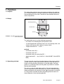
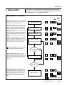
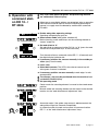
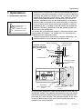
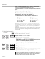
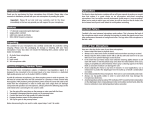
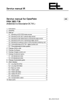
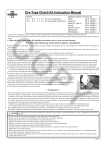
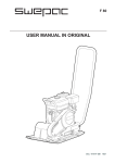
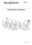
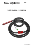
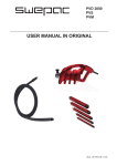
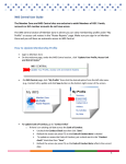
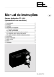
Operating manual
en
Digital web guider
DRS, SRS
Guiding by the web center
with manual sensor positioning
with digital guider RK 4004
and command device DO 10.. / RT 4006
1.
2.
3.
4.
5.
6.
7.
8.
9.
Function
Assembly
Installation
Setup editor
Commissioning with command station DO 10.. / RT 4006
Operation with command station DO 10.. / RT 4006
Optimization
Maintenance
Technical data
Component descriptions:
Sensor
Actuating element
Command stations
Digital interfaces (optional)
Control card
Electrical components (optional)
CAN bus, serial bus
Service manual (optional)
Spare parts
Parameter lists
Diagrams
3
5
5
7
9
11
13
15
15
B
D
H
I
J
U
V
W
X
Y
Z
ANL--250509-EN-01
Operating instruction notes
Explanation of symbols
➜ jobs to be performed
important information and instructions
sections of the manual due particular attention to assure the
safe operation of the web guider.
Operating manual structure
The E+L web guider manual consists of a general system description
(A), individual component descriptions (B, C, ... W), spare parts lists
(X), parameter lists (Y) and diagrams (Z).
Proceed according to the operating manual instructions. All important
operating procedures are explained in the manual. Where necessary,
reference is made to the individual component descriptions.
The block diagram includes a schematic of your system. The block
diagram also includes the address settings in the case of web guiders designed by E+L.
See the parameter lists for explanations of the individual setup parameters. See "Setup editor" section 4 for procedure on checking/
changing parameters.
Type overview
The operating manual applies for web guiders with the following actuating elements:
- pivoting frame DR
- steering roller SR
A Seite 2
Function
1. Function
1.1 Purpose
The web guider positions the moving web according to the web center. It corrects deviations from the set position and thus prevents the
web wandering off to the side. The web can be oscillated within the
sensor set position.
1.2 Design
Actuating element
Actuator AG ....
Sensor
Example: web guider DRS with pivoting
frame and sensors
The web guider consists of the following components:
- two sensors for recording the actual position value
- an actuating element (pivoting frame, turn rod, steering roller, reel
station) with actuaor and a return-to-center switch
- a digital controller DC .... or SE ..... .
optional
- command station DO ....
- command station NT ....
- command station for web offset RE ....
- digital interface DI .... (e.g. CAN PLC, CAN ARCNET, CAN INTERBUS)
1.3 Operating principle
To insert the web, move the actuating element to the center position
and the sensors to their outer position manually. Once the web is inserted, manually position the sensors at the web edge. If the web
guider is in automatic mode and the guider stop contact is enabled
the web will be guided.
The sensors scan the web edge position. If the web edge deviates
from its set position (sensor zero pont), the sensors send the magnitude and direction of the deviation to the digital controller for evaluation. The position controller corrects the guiding criterion back to its
control diagram via the actuating element.
KAP--250510-EN-01
A page 3
Function
1.3.1 Oscillating mode
A page 4
Use the oscillating mode to displace the web to the left/right around
the set position. Use remote display DO 002. or setup parameters to
set the oscillating time and stroke. On path-dependent oscillation,
the oscillating time (reel station controls) is specified by the customer.
The web continues to run during oscillation.
Assembly / Installation
2. Assembly
Please observe the locally applicable and professional safety
and accident prevention regulations!
2.1 Actuating element
➜ Mount actuating element according to attached description. See
also dimensioned or set-up drawing.
2.2 Sensors
The sensors are pre-mounted on the actuating element (sensor support beam). In exceptional cases, see sensor and actuating element
descriptions, application instructions section.
2.3 Support beam (optional)
The support beam is pre-mounted on the actuating element. In exceptional cases, see support beam description. The support beam
must be mounted so that the sensors are located immediately after
the actuating element, see also actuating element description, application instructions section.
2.4 Digital controller
The digital controller is either mounted on the actuating element or
designed for mounting in a control cabinet on-site.
The connection between control board and D.C. positioning drive
can run in one line up to a length of 3 m. However, if the distance
is between 3 m and 10 m then the motor lead and the lead of the
incremental encoder MUST run seprately.
2.5 Command stations
(optional)
3. Installation
➜ The command stations should be mounted in such a way that the
operator actually sees the equipment he is controlling (e.g. the
support beam).
Please observe the locally applicable and professional safety
and accident prevention regultions !
➜ Run electrical leads according to the attached wiring diagram.
3.1 Sensor
➜ No installation work is requried for compact systems. See the sensor description for exceptions.
3.2 Support beam (optional)
➜ No installation work is required for compact systems. See the description "Suppor beams" for exceptions.
KAP--250504-EN-01
A page 5
Assembly / Installation
A page 6
Setup editor
4. Setup editor
Parameters can be displayed and some even changed in setup
mode. You can access setup and expanded setup mode via command station DO .... or operator panel RT .... .
Basic operation in setup mode:
Parameter
Start setup mode: press the setup and additionally the increase value key (press the se tup key
first). The green LED on the key will flash.
Enter device number: press and hold down the
setup key and select parameter 0 via the increase
value key. Let go the setup key again and enter
the device number via the increase or decrease
value keys (device number is specified in block
diagram)
Enter group number: press and hold down the
setup key and select parameter 1 via the increase
value key. Let go the setup key again and enter
the group number via the increase or decrease
value keys (group number is specified in block
diagram)
Select and change parameter: press and hold
down the setup key and select the parameter you
require via the increase value key. Let go the setup key again and enter the parameter value you
wish via the increase or decrease value keys.
Parametervalue
+
Start setup mode
+
Enter device number
or
+
Enter group number
or
+
Select parameter
Change parameter value
or
Improper parameter changes can impair
the function of the entire system !
Select expanded setup mode: select device
number X.5, then press and hold down the
setup key and select parameter 3 via the increase
value key. Let go the setup key again and enter
parameter value 42 via the increase or decrease
value keys .
parameter value can be
changed
yes
no
+
Expanded setup mode
or
Select
further parameters
yes
no
Quit setup mode: select device number X.5
then press and hold down the setup key and select parameter 3 via the increase value key. Let go
the setup key again and enter parameter value 1
via the increase or decrease value keys. Press
and hold down the setup key and press the
increase value key once..Let go the setup key
again.
+
Quit setup mode
or
+
X is used as a stand-in for digits
KAP--250505-EN-01
A page 7
Setup editor
The full device address must be entered in the setup editor before
the parameters of a specific device (e.g. sensor) can be changed.
The device address is made up of the device and group number.
All device addresses are specified in the block diagram.
Parameters are selected by pressing and holding down the setup key
and then pressing the increase or decrease value key until the parameter you want appears on the display.
Once you let go the setup key the parameter value will appear on the
display. Use the increase or decrease value keys to change the parameter value.
Values are adopted or a reaction triggered by changing parameters,
i.e. by selecting the next parameter.
Parameters that cannot be edited must be selected and changed in
expanded setup mode.
A page 8
Commissioning with command station DO 10.. / RT 4006
5. Commissioning
with command
station DO 10.. /
RT 4006
No-one must be present in the danger area around the web
guider during commissioning or operation. Please observe
the locally applicable and professional safety regulations.
➜ Check that the connecting leads are correctly wired.
➜ Connect all web guider devices to the operating voltage.
➜ Check the CAN bus connections. The CAN bus connection LEDs
on the web guider and command stations will light up green, i.e.
operational. If one of the LEDs lights up red, the corresponding
CAN connection has a malfunction. Check the device and CAN
cabling.
➜ Position and check sensor, set if necessary (e.g. adjustment etc.)
see sensor description.
This terminates the commissioning for standard applications.
The settings for the following functions are listed in the descripton of the control board RK 4004:
Step size for web displacement by touch control
Oscillation
Proportional range (amplification of control loop)
Positioning speed in automatic mode
Positioning speed in manual mode
Reduction of positioning speed in the event of a web defect
Sensor emergency operation
Adaptive amplification
Early warning for limit of travel
Programmable digital inputs
Acceleration ramp manual mode
Dynamic motor current elevation
KAP--250506-EN-01
A page 9
Commissioning with command station DO 10.. / RT 4006
A page 10
Operation with command station DO 10.. / RT 4006
6. Operation with
command station DO 10.. /
RT 4006
Only insert web when web guider and processing machine
are switched off. Risk of injury!
When two or more digital guiders are networked, prior to operation
each individual control loop for which the following operating sequence is to apply must be selected by multifunction commandDO 0022.
➜ Enable web guider operating voltage
Operating voltage display goes on.
➜ Select center mode (web guider switched off)
Before inserting a new web always set the actuating element to
"center" mode first.
➜ Set web offset to "0"
Set web offset on command station DO 10.. to "0" (press the web
offset/manual adjustment keys at the same time).
Turn the web offset on command station RE 17.. (if featured) until
the digital display indicates 0.0.
➜ If necessary position the sensors manually in the outside position (away from the web)
➜ Insert web
➜ Select both sensors. The LED in the relevant sensor key will
shine green if sensor is selected.
➜ If necessary position sensors manually to web edge / to reference position.
The sensors may only be positioned when the machine is at
a standstill. Risk of injury.
➜ Set operating mode
- Center mode: the actuating element is moved to the stored center
position.
- Manual mode: the actuating element can be moved to the desired
location via the "web offset/manual adjustment" keys.
- Automatic mode: if the guider stop contact is not connected, the
web guider will go into automatic immediately.
In automatic mode, the web can be offset via command station
RE 17.. or the "web offset/manual adjustment" keys.
KAP--250511-EN-01
A page 11
Operation with command station DO 10.. / RT 4006
➜ Start processing machine
If the guider stop contact is connected the web guider will not go
into automatic until enabled by the guider stop contact.
➜ Set web offset
Use the web offset/manual adjustment keys to offset the web within the sensor measuring range. If a command station RE 17.. is
available, it alone can be used to offset the web, the "web offset/
manual adjustment" keys on DO 10../RT 4006 have no function.
A page 12
Optimisation
7. Optimization
7.1 Optimization premises
Amplification too high
Amplification right
Amplification too low
Amplification is correctly set if, after brief overshooting the error is
corrected. If the position controller is set with too great a degree of
sensitivity, the guider will overshoot as well. In the case of too little
amplification the control loop will be too slow. Optimum amplification may be determined with a characteristic curve tracer. In
practice, amplification may also be determined by trial and error:
While the web is controlled in the automatic mode it is necessary
to shortly cover up the sensor measuring range (with a piece of
cardboard for ex.) . A change of the web position will change the
web path. The level-out behavior of the web guider provides further data on the amplification.
The smaller the set proportional range at a constant maximum positioning velocity (Parameter ".1.6. velocity auto") is, the greater the
amplification of the web guider will be.
A negative proportional range causes negative amplification, the
effective direction is thus inverted in automatic mode.
Velocity correction
established correction
positioning velocity depending on proportional
range
Proportional range
.1.3. prop range ±
2,0 3,5
15 mm/s
8 mm/s
Control deviation
Positioning velocity
.1.6. velocity auto
20 mm/s
Set position
(sensor measuring range
center )
Control deviation of
1.5 mm
By reducing the proportional range the characteristic curve (see fig.)
will become steeper. The steeper the characteristic curve the greater
the positioning velocity will be in the case of a control deviation and
the system thus more sensitive. The positioning velocity of the actuator may be determined on the basis of the characteristic curve regardless of the control deviation.
KAP--250501-EN-01
A page 13
Optimisation
In this example a proportional range of 2 mm or 3.5 mm has been
assumed at a maximum motion speed of 20 mm/s.
If the control deviation is 1,5 mm the following positioning velocity will
result:
15 mm/s for a proportional range of 2 mm
8,0 mm/s for a proportional range of 3,5 mm
The values may also be calculated arithmetically:
Amplification (G) = parameter .1.6. / Parameter .1.3.
Correction velocity (VK) = control deviation * amplification (G)
Example 1:
Example 2:
1
G = 20/2 = 10 /s
G = 20/3.5 = 5.71 1/s
VK = 1.5 mm * 10 1/s
VK = 1.5 mm * 5.71 1/s
VK = 15 mm/s
VK = 8.6 mm/s
Reduce the proportional range by small steps only. Following each
change of the parameter value a web deviation should be produced
manually in automatic mode so that oscillation may be detected immediately.
Reduce the proportional range until the guider starts to oscillate. The
increase the proportional range again until no more oscillation may
be observed.
7.2 Optimizing the proportional range
➜ Select operational mode "Automatic" .
+
/
. 1. 3.
➜ Select parameter ".1.3. prop range ±" .
➜ Modify parameter value as required.
Smaller value =
web guider more responsive
Bigger value =
web guider less responsive
Each time the parameter value is changed the web should be deviated so that oscillation is detected immediately.
Leave the setup mode after setting the proportional range.
+
. . 3.
1
+
. . 4.
➜ Select parameter "..3. start service".
➜ Enter parameterwert 1.
➜ Select parameter "..4.".
By entering "1" into parameter "..3." and then changing to another
parameter a reset with data storage is activated.
If two or several digital controllers are networked it is necessary to
select the equipment address of the relevant web guider before
selecting the parameter, see chapter "Setup-Editor".
A page 14
Maintenance / Technical data
8. Maintenance
Maintenance may only be performed when the web guider
and processing machine are switched off .
8.1 Sensor
➜ See sensor description.
8.2 Support beam (optional)
➜ See support beam description.
8.3 Actuating element
➜ See actuating element description.
9. Technical
data
The technical data depend on the devices implemented and are specified in the relevant descriptions.
Technical data subject to modification without notice.
KAP--250502-EN-01
A page 15
Erhardt + Leimer GmbH
Postfach 10 15 40
D-86136 Augsburg
Telefon (0821) 24 35-0
Telefax (0821) 24 35-666