1
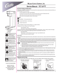
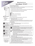
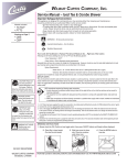
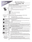
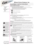
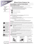
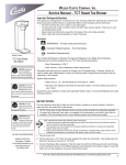
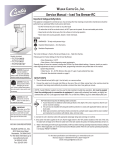
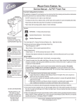
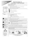
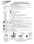
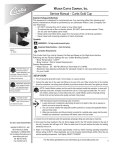
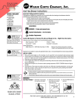
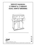
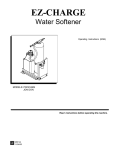
Wilbur Curtis Company, Inc. Service Manual – TCT & PTT Important Safeguards/Symbols This appliance is designed for commercial use. Any servicing other than cleaning and preventive maintenance should be performed by an authorized Wilbur Curtis service technician. • Do NOT immerse the unit in water or any other liquid • To reduce the risk of fire or electric shock, do NOT open service panels. No user serviceable parts inside. • Keep hands and other items away from hot surfaces of unit during operation. • Never clean with scouring powders, bleach or harsh chemicals. Symbols WARNINGS – To help avoid personal injury Important Notes/Cautions – from the factory Sanitation Requirements The Curtis G3 Brewer is Factory Pre-Set and Ready to Go… Right from the Box. Following are the Factory Settings for the G3 Iced Tea Brewer. Models Included: • TCTS/T • PTT3 CAUTION: Equipment must be installed to comply with applicable federal, state, and local plumbing/ electrical codes having jurisdiction. CAUTION: Follow this setup procedure before attempting to use this unit. Failure to follow these instructions can result in injury and/or void of warranty. CAUTION: DO NOT connect the unit to hot water. The inlet valve is not rated for hot water. IMPORTANT: After setup, run a FULL brewcycle. Place a tea container to catch both hot water from the brewcone and dilution water from spout on the front cover. • Brew Temperature = 204°F • Brew Volume = Set to dispensing vessel requirements (2.2 liters) Generally there will never be a reason to change the G3/Gold Cup Series default settings. However, should you need to make slight adjustments to meet your brewing needs, programming instructions are provided later in this manual. System Requirements: • Water Source 20 – 90 PSI. Minimum flow rate of ½ gpm (1 gpm preferred flow rate). • Electrical: See electrical schematic on page 6. SETUP STEPS The unit should be level (left to right and front to back), and located on a secure counter top. Connect a water line from the water filter to the brewer. NOTE: A water filtration device must be used to maintain a trouble-free operation. (In areas with extremely hard water, we suggest that a sedimentary and taste & odor filter be installed.) This will prolong the life of your brewing system and enhance coffee quality. NSF International requires the following water connection: 1. A quick disconnect or additional coiled tubing (at least 2x the depth of the unit) so that the machine can be moved for cleaning underneath. 2. In some areas an approved backflow prevention device may be required between the brewer and the water supply. 3. Water pipe connections and fixtures directly connected to a potable water supply shall be sized, installed and maintained in accordance with federal, state, and local codes. 1. A 1/4” Flare has been supplied for water line connection. Use tubing sized sufficiently to provide ½ GPM (preferred flow rate is 1gpm). 2. Connect the unit to an appropriate electrical power circuit. 3. Turn on the toggle (STANDBY/ON) switch behind the unit. The heating tank will start to fill. When the water level in the tank rises to the correct volume, the heating element will energize automatically. With G3 tea brewers there is no danger of element burnout caused by an empty tank. 4. The heating tank will require 20 to 30 minutes to reach operating temperature (204°F) as indicated by the READY-TO-BREW LCD readout. 5. Important: Run one full brewcycle, to purge the water lines and valves of air. Five seconds of dilution water at the beginning of each brewcycle is normal pre-programmed operating behavior. BREWING INSTRUCTIONS WARNING HOT LIQUID, Scalding may occur. Avoid splashing. 1. Brewer should be ON (Confirm at rear toggle switch, then press ON/OFF button) and Ready-to-Brew displayed. 2. Place filter in brew basket. Pour leaf tea into basket. 3. Slide brew cone into brew rails. Place tea container under brew cone. 4. Press the BREW button to brew tea. ISO 9001:2008 REGISTERED WILBUR CURTIS CO. Montebello, CA 90640 For the latest information go to www.wilburcurtis.com Tel: 800/421-6150 1 Programming Your Curtis Generation 3 Brewer is Factory Pre‑Set for Optimum Performance. After connection to water and power; the rear toggle switch must be on. You will hear a beep sound, indicating power is available to the controller. The control displays CURTIS < TCT > CURTIS . Press ON/OFF button and the screen will display . After three seconds, Water will fill the tank (approximately 2-3 minutes depending on water flow rate). When the proper level is reached screen. It takes approximately 20 minutes to reach set point temperature of 204°F. CURTIS Control will displayREADY to BREW CURTIS FILLING CURTIS HEATING is displayed. will appear on the when temperature reaches the set point (204°F). Unit is now ready to brew. To Go Into Programming Turn off (dark display) by pressing ON/OFF button (yellow). Press and hold BREW button 4 (green) and then press and release ON/OFF button (yellow). Continue holding BREW button. Display will read spond to the buttons (see illustration below). The default code set at the factory is 1‑2‑3‑4. Then , wait until is displayed Enter the 4‑digit access code, the digits 1‑4 corre- will be displayed. All programming selections are performed with the three center buttons. The symbols below the buttons are: 1 2 3 4 Scroll LEFT SELECTION or ENTER to save new parameter Scroll RIGHT SPRAYHEADS: Mentioned in this Programming guide are the words Gray and Purple. This refers to the color of the sprayhead. The current sprayhead is the purple AFS. The older version is the gray sprayhead. See the illustration at right. GRAY PURPLE Program Menus Program Menus Program Menus screen. Press > button, to show the next menu item. Recipes (Factory set to Standard Tea Purple) Press to Select. Press < or > to scroll through recipes: Standard Gray, Standard Purple, Tropical Gray, Tropical Purple, 76/308 Gray or 76/308 Purple. Press to set. Recipes Tea by Volume: Press to select, Display will now show Push START To Begin... Press the BREW button then hot water starts running, when desired volume is reached press BREW button again to stop the flow. Now the volume has been set. Pressing > button will display the subsequent menu features. Tea By Volume * Tea By Time * Tea by Time (Factory set to 5:52) Press to select. By pressing < or > buttons, you can increase and decrease time. Press to set minutes and seconds. Units with the half batch option, the Half Batch brew button is factory set at for half the brew time (2:56). Tea Dilut Delay * Tea Dilution Delay (Factory set to 0:30) Press to Select. Press < or > buttons, to add or decrease time. Press to set. Tea Dilut Volume * Tea Dilution Volume: Press to Select, Display will now show Push START To Begin... Press the BREW button and water will flow, when desired volume is reached press BREW button again to stop the flow. Now the volume has been set. Press > to display subsequent menu features. Tea Dilut Time * Dilution Time (Factory set to 4:05) Press to Select. By pressing < or > buttons, you can increase and decrease time. Press to set minutes and seconds. * On units with the half batch option, the half batch brew button may be independently set. 2 Continued on Page 3 Programming Tea Dilut Stir Tea Dilution Stir (Factory set to ON). Press to Select. Press < or > buttons, to toggle between OFF and ON. Press to set. Tea Pulse Brew Tea Pulse Brew (Factory set to OFF). Press to Select. Press < or > to select ON, OFF or D. D is a manual adjust from 1 to 20 pulses with an ON time from 5 to 150 seconds and an OFF time from 5 to 150 seconds. Tea Fast Brew Tea Fast Brew (Factory set to OFF). Press to Select, press < or > to choose ON or OFF. Selecting ON will start hot water spraying in the brewcone first and then 1 minute later the dilution water will start to flow. Tea Half Batch Tea Half Batch (Factory set to OFF). Press to Select. Press < or > buttons, to toggle between OFF and ON. Press to set. Tea Drip-Out Tea Drip-Out (Factory set to OFF) Press to Select. Press < or > to adjust time. Settings are OFF, up to 15 minutes, at one minute increments. Temperature Temperature (Factory set to 204ºF) Press to Select. Press < or > to increase or decrease setting. Temperature range, from 170ºF to 208ºF in 2‑degree increments. Energy Save Mode Brew Count Odom Brew Count Total Cold Brew Lock Energy Save Mode (Factory set to OFF) Press to Select, < or > ON, OFF or ON 140ºF , to set. When in ON, unit will automatically shut off 4 hours from last brew. When feature is OFF, unit does not have the energy saving mode. In the ON 140ºF position, temperature goes down to 140ºF. if unit has not brewed in 4 hours. This feature will save energy by maintaining a lower temperature in the tank during periods of non‑operation. Brew Count Odom. Press to Select, Shows total gallons and total brew cycles on the unit. Press ex or Reset Brew Count Total. Brew Count Total Press to Select, Shows total gallons and total brew cycles on the unit. Cannot be reset. Cold Brew Lock (Factory set to 5º F) Press to select, < or > to select desired setting (CBL 5, 15 or OFF), to set. The Cold Brew Lock feature allows the brewer to brew at three different temperature levels from the actual set point. The first setting is within 5 degrees of set point, next is within 15 degrees of set point, OFF is within 30 degrees of set point for the Ready to Brew message, however it will brew at any temperature. Master Reset Master Reset Press to display Are You Sure? Then < for Yes, > for No. When Master Reset is used, the all of the menu selections in the UCM return to factory defaults. Service Call Service Call (Phone number Factory set to 1-800-000-0000) Press to display number and change number or < to move place and EX to exit when complete. This number will be displayed during a Heating system SENSOR ERROR or during a WATER ERROR. Access Code Access Code (Factory set to 1‑2‑3‑4) Press to display number and change number, (the number can be changed 1 to 4) or < to move place and ex to exit when complete. Continued on Page 4 3 Programming Banner Name P-Maintenance Beeper On/Off Banner Name (Factory set to CURTIS) Press to display letters and change letters or < to move place and EX to exit when complete This feature allows up to 14 letters to be programmed for company name or regional name. Programming all blanks disables Banner Name. If programmed, Banner Name is displayed every 5 sec. on and off. P-Maintenance (Factory set to OFF) Press to Select, Set gallons brewed to indicate P-Maintenance. Press < or > to adjust from Off to 3000 gallons. Press to exit. Beeper On/Off (Factory set to ON) Press to display ON or OFF. Pressing either < or > toggles between on and off. to set. When ON, this feature allows you to hear a short beep each time a button is pressed. Quality Timer Quality Timer (Factory set to OFF) Press to Select. By pressing < or > buttons, you can increase and decrease time. Setting range is from 0 to 10 hours in 1 hour increments. Press to set. Expired time indicated by audio alarm and flashing “Quality Timer”. Display Brew Time Display Brew Time (Factory set to ON) Press to Select. Pressing < or > toggles between ON and OFF. Display Messages (Factory set to ON) Display Messages Press to display ON or OFF. Pressing either < or > toggles between on and off. This feature allows the operator to select the message “Rinse Server Before Brewing”. This will be displayed any time the unit is not brewing. Model Select Exit Model Select (Factory set to 1/Half Batch) Press to Select. Pressing < or > toggles between 1/Half Batch and 3-Batch. Exit Press to select, exits program mode and returns unit to operation. Pressing > returns you to Tea Recipes. Tank Temperature Check Turn on brewer at the control panel ON/OFF button. Press and hold will be displayed (temperature in heating tank). button (see illustration, page 2) for 5 seconds. Water Temperature Error Message With G3/Gold Cup Series brewers, there are three error messages that can appear on the screen to advise the user of a malfunction. If one of these error messages appear, the brewer will lock up and stop functioning until the error is corrected. An error message will occur under the following conditions: 4 (800) 000-000 Water Level Err 1. Water level fill error or overflow. This error message occurs when the inlet valve solenoid has been on for more than 10 minutes. This error message also occurs when the valve is refilling the tank during a brew cycle for more than 1½ minutes. (800) 000-000 Sensor Err 2. Water temperature control system error. An open probe or a break in the temperature control circuit is detected. The screen may display a phone number to call for service. After the malfunction is corrected, the error message must be cleared. To reset the control panel and return to normal operation, press for 5 seconds. Illustrated Parts TCT 18A 18 6 19 7 8 20 22 23 24 9 5 5B 25 26 1 2 3 10 32 11 29 28 21 12 5A 14 13A 31A 30 4 27 16 17 16A 33 31 13 15 A 5 PARTS LIST 6 ITEM 1 2 2A 3 4 5 5A 5B 6 7 8 8A 9 9A 10 10A 11 11A 12 13 13A 14 14A 14B 14C 14D 14E 15 16 16A 17 18 18A 19 20 21 22 23 24 25 26 27 28 29 30 31 31A 32 33 PART Nº DESCRIPTION WC-3301 BASKET, WIRE 7.00 DIA. USE WITH WC-3311 (OPTNL) WC-3647 STRAINER BT-10 BREWCONE (EXCEPT PARADISE) WC-8532 STRAINER, TROPICAL BREWCONE WC-3320 BREW CONE W/HANDLE 8.8” D W/STRNR (OPTIONAL) WC-3201 HANDLE, BREW CONE BLACK FOR WC-3320 WC-3398 BREW CONE, ASSY STD TEA NON-METAL W/BLU GUARD WC-3358 BREWCONE W/WC-3320, WC-3301 & WC-3647 (OPTNL) WC-3399 BREW CONE, ASSY TROPICAL TEA NON-MTL W/YEL GUARD WC-58117 COVER, TOP BREWER WC-2977-101K KIT,SPRAYHEAD FITTING PLASTIC WC-37189* UCM KIT, LABEL & OVERLAY 120V TCTS/T WC-37338 KIT, UCM & OVERLAY W/HALF BATCH BREW TCTS WC-39398* LABEL, UCM PANEL TCT/PTT GT3 W/O FAUCET CURTIS WC-39628 LABEL, UCM PANEL W/HALF BATCH W/O FAUCET WC-29025* SPRAYHEAD, PURPLE ADVANCE FLOW WC-2942 SPRAYHEAD, GRAY (OLDER UNITS) WC-66079 SPOUT ASSY , DILUTION PLASTIC WC-2965 SPOUT, BYPASS ASSEMBLY WC-8556* HEAT SINK ASSY DV WC-37255 KIT, DUAL VALVE WATER INLET WC-2401 ELBOW, 3/8 NPT X 1/4 FLARE PLATED WC-58017-104 COVER, FRONT TCTS WC-58021-103 COVER, FRONT CENTER WRAP TCTT WC-58101-102 COVER, CENTER WRAP PTT3 WC-58017 COVER, CENTER WRAP TCT-35S TCTDP-35S (OLDER UNITS) WC-58021 COVER, FRONT CENTER WRAP TCTT/TCTD-35S (OLDER UNITS) WC-58101 COVER, CENTER WRAP SS PTT3 (OLDER UNITS) WC- 102* SWITCH, TOGGLE SPST 25A 125/250VAC RESISTIVE WC-3518 LEG, GLIDE 3/8”-16 STUD SCREW WC-3503 LEG, 8-32 STD SCREW BUMPER WC-8531 RAIL, BASE TCTD WC-5853-102 COVER, TOP HEATING TANK GEN USE WC-5851 COVER, TANK W NOTCHES (OLDER UNITS) WC-43062 GASKET, TANK LID WC-6277 TANK, COMPLETE 1600W 120V WC-5231* COMPOUND SILICONE 5 OZ WC-5502-01* KIT, PROBE, ASSY WATER LEVEL W/HEX FITTING, O-RING & NUT WC- 904-04* ELEMENT, HEATING 1.6KW 120V W/JAM NUTS WC-4394 SHOCK GUARD, HEATING ELEMENT WC-1438-101* SENSOR, TEMPERATURE TANK WC- 523* THERMOSTAT, MANUAL RESET 120/220V 25A 220ºF MAX WC-5310* TUBING, 5/16” ID X 1/8” W SILICONE WC-2707 TEE, FLARE ¼ x ¼ x ⅜ BRASS WC-53038 TUBE ASSY, FLEXIBLE 1/4 FLARE 11-1/8” WC- 826L* VALVE, INLET 1 GPM 120V 10W WC- 895-105 VALVE, INLET DUAL 120V 10W 2 GPM X .5 GPM WC- 801* VALVE, INLET BRASS .50 GPM 120V 10W RU/WB (OLDER UNITS) WC-43134 O’RING, .426 X 9/16 O.D X .070 WALL EDPM TCTS WC- 810-103 VALVE, CHECK 3/8 X 3/8 BARB SS WITH O-RING & .010 SPRING * RECOMMENDED PARTS TO STOCK Illustrated Parts List TCO 3 1 2 4 6 5 7 ITEM PART Nº DESCRIPTION 1 WC-5683 LID ASSY, TCO 2 WC-38471 LABEL, FRONT ICED TEA GENERIC 3 WC-3724* KIT, EZ-VIEW REPLACEMENT (OLDER UNITS) 4 WC-1803 FAUCET, SPB 5 WC-1805* SEAT CUP, FAUCET S’ 6 WC-3707* KIT, REPAIR SPB FAUCET 7 WC-37260* KIT, FAUCET W/ADAPTER COMPLETE * RECOMMENDED PARTS TO STOCK 7 Illustrated Parts List TCN 1 2 5 4 6 3 10 7 8 9 ITEM PART Nº DESCRIPTION 1 WC-61436 LID, BLACK PLASTIC TCN 2 WC-38471 LABEL, FRONT TCN GENERIC 3 WC-1803* FAUCET, SPB 4 WC-37260 KIT, FAUCET W/ADAPTER COMPLETE 5 WC-3707* KIT, REPAIR SPB FAUCET 6 WC-1805* SEAT CUP, FAUCET S’ 7 WC-38163 LABEL, CURTIS SWP CLR/WHT 8 WC-5686 DRIP TRAY, OCTAGON STYLE 9 WC-3531* LEG, PLASTIC GLIDE TCN 10 WC-3289 HANDLE, GASKET * RECOMMENDED PARTS TO STOCK 8 TCT ELECTRICAL SCHEMATIC 9 TEA TIPS WARNING DO NOT refrigerate unused tea overnight for later consumption. CLEANING IMPORTANT: If the brew cone comes with a screen; clean the screen to maintain the tea flow. Neglecting this screen will eventually cause the brewcone to overflow, spilling hot liquid over the unit. CAUTION: DO NOT use undiluted bleach or chlorine. 1. Store tea bags in a dark, cool and dry place away from strong odors and moisture. Do not refrigerate. 2. Never hold finished brewed tea for more than eight hours at room temperature. Discard any unused tea after eight hours 3. Brew only enough tea that you reasonably expect to serve within a few hours. 4. To protect tea flavor and to avoid bacterial contamination and growth, clean and sanitize tea brewing, storage and dispensing equipment at least once a day. Regular cleaning of your airpots and tea containers will maintain the highest quality coffee and iced tea your equipment is capable of producing. A proper cleaning is essential in preserving the appearance of the brewer. 1. Turn off the tea brewer at the ON/OFF button on the front control panel. 2. Wipe exterior surfaces with a damp cloth, removing spills and debris. 3. Slide the brewcone out and clean it. Thoroughly soap the sprayhead area with a mild detergent solution. 4. Wash the brewcone and wire brew basket, if applicable. Use a soft bristled brush for hard to clean areas. Wash both parts with a detergent solution or put these parts through a dishwasher. 5. Wash the tea container and top cover. Use a detergent solution and a soft bristled brush to clean inside the container. Wipe the exterior surfaces with a sponge and detergent solution. Rinse thoroughly. 6. Clean the faucet assembly. Unscrew the handle assembly from the faucet and remove. Clean the faucet shank with a gage glass brush (circular bristle) by pushing the brush through the shank. Using the same brush clean the faucet body inlet and outlet. Clean the faucet cap and silicone seat cup. 7. After the cleaning, place the parts (sprayhead, brewcone and basket and faucet parts) into a sink to be sanitized. To sanitize the disassembled parts: A. Use a clean container to submerge all parts. Wear rubber gloves for protection. B. Immerse in commercial Bar Tabs/Sani-Tabs sanitizing solution The solution must be warm (75°F.) Let the parts soak for at least one minute. 8. Thoroughly rinse parts with hot water. Air dry, all parts that were sanitized. 9. After cleaning, sanitizing and drying, assemble any parts taken from the tea container. 10. Clean out airpots with a sponge brush and a mild detergent solution. To remove mineral deposits, fill liner with vinegar and allow to soak. LIQUID LEVEL PROBE Cleaning intervals for the probe are to be determined by the user or the service tech based on water conditions. The use of water filters, or the type of water filter that is being used can impact the service interval. Intervals can be from one month to several years, however, replacing rather than cleaning the probe is preferable. WARNING: Disconnect electrical power before removing access panels. CAUTION: This procedure involves working with hot water and hot surfaces. 1. Unplug the power cord and shut off the water line. 2. Remove the top cover of the unit. Locate the top of the tank and remove the cover. 3. Drain the tank to a level about 3” below the tip of the probe. 4. Allow some time for the probe to cool before working on the brewer. 5. Clean the tip of the probe using a Scotch-BriteTM scuff pad. 10 6. If a residual white layer is still visible on the probe, remove the probe and soak it in vinegar or a scale removing chemical. Repeat this step until the white layer is removed. TCT ROUGH-IN DRAWING PTT ROUGH-IN DRAWING 11 Product Warranty Information The Wilbur Curtis Company certifies that its products are free from defects in material and workmanship under normal use. The following limited warranties and conditions apply: 3 Years, Parts and Labor, from Original Date of Purchase on digital control boards. 2 Years, Parts, from Original Date of Purchase on all other electrical components, fittings and tubing. 1 Year, Labor, from Original Date of Purchase on all electrical components, fittings and tubing. Additionally, the Wilbur Curtis Company warrants its Grinding Burrs for Forty (40) months from date of purchase or 40,000 pounds of coffee, whichever comes first. Stainless Steel components are warranted for two (2) years from date of purchase against leaking or pitting and replacement parts are warranted for ninety (90) days from date of purchase or for the remainder of the limited warranty period of the equipment in which the component is installed. All in-warranty service calls must have prior authorization. For Authorization, call the Technical Support Department at 1-800-9950417. Effective date of this policy is April 1, 2003. Additional conditions may apply. Go to www.wilburcurtis.com to view the full product warranty information. CONDITIONS & EXCEPTIONS The warranty covers original equipment at time of purchase only. The Wilbur Curtis Company, Inc., assumes no responsibility for substitute replacement parts installed on Curtis equipment that have not been purchased from the Wilbur Curtis Company, Inc. The Wilbur Curtis Company will not accept any responsibility if the following conditions are not met. The warranty does not cover and is void under the following circumstances: 1) 2) 3) 4) 5) 6) 7) 8) 9) Improper operation of equipment: The equipment must be used for its designed and intended purpose and function. Improper installation of equipment: This equipment must be installed by a professional technician and must comply with all local electrical, mechanical and plumbing codes. Improper voltage: Equipment must be installed at the voltage stated on the serial plate supplied with this equipment. Improper water supply: This includes, but is not limited to, excessive or low water pressure, and inadequate or fluctuating water flow rate. Adjustments and cleaning: The resetting of safety thermostats and circuit breakers, programming and temperature adjustments are the responsibility of the equipment owner. The owner is responsible for proper cleaning and regular maintenance of this equipment. Damaged in transit: Equipment damaged in transit is the responsibility of the freight company and a claim should be made with the carrier. Abuse or neglect (including failure to periodically clean or remove lime accumulations): Manufacturer is not responsible for variation in equipment operation due to excessive lime or local water conditions. The equipment must be maintained according to the manufacturer’s recommendations. Replacement of items subject to normal use and wear: This shall include, but is not limited to, light bulbs, shear disks, “0” rings, gaskets, silicone tube, canister assemblies, whipper chambers and plates, mixing bowls, agitation assemblies and whipper propellers. Repairs and/or Replacements are subject to our decision that the workmanship or parts were faulty and the defects showed up under normal use. All labor shall be performed during regular working hours. Overtime charges are the responsibility of the owner. Charges incurred by delays, waiting time, or operating restrictions that hinder the service technician’s ability to perform service is the responsibility of the owner of the equipment. This includes institutional and correctional facilities. The Wilbur Curtis Company will allow up to 100 miles, round trip, per in-warranty service call. RETURN MERCHANDISE AUTHORIZATION: All claims under this warranty must be submitted to the Wilbur Curtis Company Technical Support Department prior to performing any repair work or return of this equipment to the factory. All returned equipment must be repackaged properly in the original carton. No units will be accepted if they are damaged in transit due to improper packaging. NO UNITS OR PARTS WILL BE ACCEPTED WITHOUT A RETURN MERCHANDISE AUTHORIZATION (RMA). RMA NUMBER MUST BE MARKED ON THE CARTON OR SHIPPING LABEL. All in-warranty service calls must be performed by an authorized service agent. Call the Wilbur Curtis Technical Support Department to find an agent near you. Rev S . ECN 14598 . 12/7/[email protected] Rev R . ECN 14359 . 8/21/[email protected] Rev Q . ECN 13707WILBUR . 12/27/[email protected] CURTIS CO., INC. ECN 13004 . 3/4/116913 @ 7.5Acco St., Montebello, CA 90640-5403 USA ECN 12167 . 2/24/10 @ 15.0800/421-6150 . EAR 8219 Phone: Fax: 323-837-2410 Technical Support Phone: 800/995-0417 (M-F 5:30A - 4:00P PST) Web Site: www.wilburcurtis.com E-Mail: [email protected] FOR THE LATEST SPECIFICATION INFORMATION GO TO WWW.WILBURCURTIS.COM Printed in U.S.A. 12/2012 F-3329-S Rev S