1
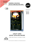
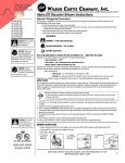
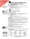
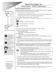
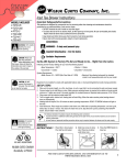
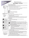
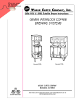
F IND
OUT MORE
ON THE WEB .
W I L B U RC U RT I S . C O M
W ILBUR CURTIS COMP
ANY, I NC.
OMPANY
D500 Generation 3 - Airpot Brewer Instructions
Models Included
• D500GT
• D500GT/H
Important Safeguards/Conventions
This appliance is designed for commercial use. Any servicing other than cleaning and maintenance
should be performed by an authorized Wilbur Curtis service center.
• Do NOT immerse the unit in water or any other liquid
• To reduce the risk of fire or electric shock, do NOT open top or rear panel. No user serviceable parts inside. Repair should
be done only by authorized service personnel.
• Keep hands and other items away from hot parts of unit during operation.
• Never clean with scouring powders, bleach or harsh implements.
Conventions
WARNING HOT LIQUID,
Scalding may occur.
Avoid splashing.
CAUTION: Please use
this setup procedure
before attempting to use
this brewer. Failure to follow the
instructions can result in injury or
the voiding of the warranty.
CAUTION: DO NOT
connect this brewer to
hot water. The inlet valve
is not rated for hot water.
W ARNINGS – To help aavoid
void personal injur
injuryy
Important Notes/Cautions – from the factory
Sanitation
Requirements
Your Curtis ADS System is FFactor
actor
actoryy Pre-Set and Read
Readyy to Go… Right out of the Carton.
Following are the Factory Settings for your D500GT Airpot Coffee Brewing System:
ture = 200°F
• Brew Tempera
emperature
• Brew Volume = Set to dispensing vessel requirements (2.2 liters)
Generally there will never be a reason to change your ADS programming. However, should you need to make slight adjustments
to meet your brewing needs, programming instructions are provided later in this manual.
System Requirements:
• Water Source 20 – 90 PSI (Minimum Flow Rate of 1 GPM)
• Electrical: See attached schematic for standard model or visit www.wilburcurtis.com for your model.
Equipment to be installed to comply with applicable federal, state, or local plumbing/electrical codes having jurisdiction.
SETUP STEPS
CAUTION: When
cleaning, DO NOT use
powders, liquids,
cleansers, or any substance
containing chlorine. These
products promote corrosion,
cause pitting of stainless steel and
will void the warranty.
The unit should be level (left to right and front to back), located on a solid counter top. Connect a water line from the water filter to the
brewer. NOTE: Some type of water filtration device must be used to maintain a trouble-free operation. (In areas with extremely hard
water, we suggest that a sedimentary and taste & odor filter be installed.) This will prolong the life of your brewing system and
enhance coffee quality.
The National Sanitation Foundation requires the following water connection:
1. A quick disconnect or additional coiled tubing (at least 2x the depth of the unit) so that the machine can be moved
for cleaning underneath.
2. In some areas an approved backflow prevention device may be required between the brewer and water supply.
1. A 3/8” NPT x 1/4” Flare elbow has been supplied for water line connection. Use tubing sized sufficiently to provide a minimum of
1.0 GPM.
2. Connect the unit to an appropriate electrical power circuit.
3. Turn on the toggle (STANDBY/ON) switch behind the unit. The heating tank will start to fill. When the water level in the tank rises
to the correct volume, the heating elements will energize automatically. With ADS Systems there is no danger of element burnout
caused by an empty tank.
4. The heating tank will require 20 to 30 minutes to reach operating temperature (200°F) as indicated by the READY-TO-BREW
indicator light.
5. Prior to brewing, dispense 12 ounces of hot water through the hot water faucet.
6. Brew a cycle of at least 12 ounces, to purge the water lines of any air that may be trapped after filling.
BREWING INSTRUCTIONS
1. Brewer should be ON (Confirm at rear toggle switch, then press ON/OFF button). Ready-to-Brew should be displayed.
2. Place empty airpot on deck.
3. Place filter in brewcone.
C
ISO 9001 REGISTERED
WILBUR CURTIS COMPANY
Montebello, CA 90640
4. Pour ground
coffee into
brewcone.
5. Position
brewcone
into brew
rails.
6.Press Brew
button.
FOR THE LATEST SPECIFICATIONS AND INFORMATION GO TO
WWW.WILBURCURTIS.COM
1
Quick Start
D500 GT
Your Curtis ADS System is FFactor
actor
erformance.
actoryy Pre-Set for Optimum PPerformance.
After connection to water and power; the rear toggle switch must be on. You will hear a beep sound, indicating power is available to the controller.
The control displays
WILBUR CURTIS
. Press ON/OFF button and the screen will display
<Airpot Brewer>
WILBUR CURTIS
. After three seconds,
Water will fill the tank (approximately 2-3 minutes depending on water flow rate). When the proper level is reached
screen. It takes approximately 20 minutes to reach setpoint temperature of 200°F.
Control will display
WILBUR CURTIS
READY TO BREW
WILBUR CURTIS
FILLING
WILBUR CURTIS
HEATING
is displayed.
will appear on the
when temperature reaches the setpoint (200°F). Unit is now ready to brew.
To Go Into Programming
Turn off (dark display) by pressing ON/OFF button (yellow). Press and hold BREW button (green) and then press and release ON/OFF button (yellow).
Continue holding BREW button. Display will read
correspond to the buttons (see illustration below).
ENTERING PROGRAM
MODE
, wait until
ENTER CODE
– – – –
is displayed Enter the 4-digit access code, the digits 1-4
The default code set at the factory is 1-2-3-4. Then
displayed.
<
PROGRAM MENUS
SELECT
>
will be
All programming selections are performed with the three center buttons.
The symbols below the buttons are:
Scroll LEFT
1
2
PROGRAM MENUS
During actual brew cycle a
2-minute drip mode is added to
the brew time. The programmed
water level compensates for back
to back brewing in Delta 3 to allow
for an increase of water volume.
3
4
SELECTION or ENTER to save new parameter
Scroll RIGHT
Brew Volume (Factory set to 2.2 Liters)
Selecting Brew by Volume or Brew by Time depends on whether you know your brew time before starting.
From Program Menus press > display will now show the next feature.
Brew by Volume
olume: Press to Select, Display will now show Push START To Begin... Press the BREW button then hot water starts running, when desired
volume is reached press BREW button again to stop the flow. Now the volume has been set. Pressing > button will display the subsequent menu features.
Next item in the sequence is Brew by Time. Press to Select to change the brew time. Display will now show the current time. By pressing < or > you can
toggle back and forth from minutes to seconds to exit (ex). Change the time or set and exit by pressing .
Tempera ture (F
actor y set to 200
F)
(Factor
200°F)
Press to Select. Press < or > to move to desired temperature and then to set. Temperature is programmable from 170ºF to 204ºF in 2-degree increments.
Energy Save Mode (Factory set to OFF)
Press to Select, < or > ON, OFF or ON 140ºF , to set. When in ON, unit will automatically shut off 4 hours from last brew. When feature is OFF, unit does not have the energy saving mode.
In the ON 140ºF position, temperature goes down to 140ºF. if unit has not brewed in 4 hours. This feature will save energy by not heating the tank during periods of non-operation.
Brew Count Odom.
Press to display total brew cycles. Press ex or Reset
Pre-Infusion (Factory set to OFF)
Press to Select. Current setting in seconds is displayed < to decrease or select > to increase (range from OFF to 10 through 60 seconds), to set.
If Pre-infusion is selected (ON), Cold Brew Lock is set to Delta 1 within 5ºF of set point and Cold Brew Lock is dissappears from the list of program selections. When Pre-infusion is ON, Pulse Brew
dissappears from the list of program selections.
Brew Count Total
Press to Select, Shows total gallons and total brew cycles on the unit. Not resettable.
Cold Brew Lock . . . (Factory set to OFF)
Press to select, < or > to select desired setting (CBL 5, 15 or OFF), to set.
The Cold Brew Lock feature allows the brewer to brew at three different temperature levels from the actual set point. The first setting is within 5 degrees of set point, next is within 15 degrees of set point, OFF
is within 30 degrees of set point for the Ready to Brew message, however it will brew at any temperature. This feature will operate after initialization to set temperature after the rear standby toggle switch is
reset to ON.
Master Reset
Press
to display Are You Sure?
Then < for Yes
es, > for No
No.
Brewer factory defaults are then reset.
Service Call (Phone number Factory set to [800] 995-0417)
Press to display number and change number or < to move place and EX to exit when complete This number will be displayed during a Heating system SENSOR ERROR or during a WATER ERROR.
Access Code (Factory set to 1-2-3-4)
Press to display number and change number, (the number can be change 1 to 4) or < to move place and ex to exit when complete.
Banner Name (Factory set to WILBUR CURTIS)
Press to display letters and change letters or < to move place and EX to exit when complete
This feature allows up to 14 letters to be programmed for company name or regional name. Programming all blanks disables Banner Name. If programmed, Banner Name is displayed every 5 sec. on and off.
P-Maintenance (Factory set to OFF)
Press to Select, Set gallons brewed to indicate P-Maintenance. Press < or > to adjust from Off to 3000 gallons. Press to exit.
Beeper On/Off (Factory set to ON)
Press to display ON or OFF. Pressing either < or > toggles between on and off. to set.
2
Pulse Brew (Factory set to OFF)
Press to select, < or > to select OFF or one of four pulse patterns (A to D) .
Guidelines for Pulse Brew:
This feature allows tuning of the coffee flavor. This option should only be used with the standard Gray or Purple AFS sprayheads. The pot level should always be set first with this option OFF.
Depending on your grind profile and water conditions, the three Pulse Brew options help “tune” or change the coffee flavor. Filter Pack type coffees typically extract better with the A and B pulse setting.
Decaffeinated coffees typically extract better with the B pulse setting. High-Yield coffees typically extract better with the C pulse setting. Of course, any of the A, B or C settings may be used to suit your taste
profile.
If Pulse Brew is selected (ON), Cold Brew Lock is set to Delta 1 within 5ºF of set point and Cold Brew Lock disappears from the list of program selections.
When Pulse Brew is ON, Pre-infusion disappear from the list of program selections.
Model Select
Press to select, < or > to select desired model (ALPHA-1, ALPHA-2, ALPHA-3/4/5, Airpot Brewer, Thermo-Alpha) Press
Exit
Press to select, exits program mode and returns unit to operation.
to set. The control will reset itself when a new model is selected.
Tank Tempera
ture Check
emperature
Turn on brewer at the control panel ON/OFF button. Press and hold 3 button (see illustration, page 2) for 5 seconds. Water Temperature will be displayed (temperature in heating tank).
PARTS DIAGRAMS
18
19
16
25
20
21
27
26
22
28
23
17
16
24
29
D
15
6
7
D
1
Illustrated Parts List
Nº
1
2
3
4
5
5A
5B
6
7
8
9
10
11
12
13
14
15
16
17
18
19
20
21
22
23
23A
24
25
26
27
28
29
Part N
Nº
WC-2977
WC-37064
WC-39346
WC-1809
WC-3621
WC-3316
WC-3316-101
WC-5310
WC-5450
WC- 889
WC-2936
WC- 102
WC-6221
WC-3503
WC- 826
WC-8591
WC-3763
WC-3765
WC- 830
WC-6277
WC-5851
WC-5502-01
WC- 917
WC-4394
WC- 522
WC- 523
WC-43055
WC-43062
WC-43058
WC-1438-101
WC-5231
WC-37098
Description
FITTING ASSY, SPRAYHEAD
KIT, LABEL & UCM D500GT CURTIS
LABEL, CNTRL PNL (CURTIS LOGO)
FAUCET, HOT WATER W/JAM NUT
BREWCONE, UNIV7 1/8" BLK PLASTIC
BREW CONE, ASSY S.S. (OPTIONAL)
BREWCONE ASSY, WITH BYPASS (OPTNL)
TUBING, SILICONE, 5/16" I.D. ( 1 FT.)
COVER, TOP
VALVE, DUMP RIGHT 120V
SPRAYHEAD, RED (.131 DIA.)
SWITCH, TOGGLE 125/250 VAC RESISTIVE
GRID, DRIP TRAY AIRPOT
LEG, SCREW BUMPER 3/8-16 STD
VALVE, INLET 1 GPM 120V 10W
CAPACITOR, X2
KIT, VALVE REPAIR USE ON WC-889
KIT, VALVE REPAIR USE ON WC-826
WASHER, FLW ½” 1.0 GPM USE W/WC-826
TANK COMPLETE, D500GT 120V
COVER, TANK W/NOTCHES
PROBE ASSY, WATER LEVEL
HEATING ELMNT 1450W 120V W/NUTS
GUARD, SHOCK HEATING ELEMENT
THERMOSTAT, HI LIMIT HEATER CONTROL
THERMOSTAT, MANUAL RESET
GUARD, SHOCK RESET THERMOSTAT
GASKET, HEATING TANK
PLUG, TANK DRAIN, PP RED
SENSOR, HEATING TANK
COMPOUND, SILICONE 5 OZ TUBE
KIT, BYPASS GEN USE
8
2
3
– D500GT
4
5
5A
9
13
10
11
12
14
5B
3
ELECTRICAL
SCHEMA
TIC
SCHEMATIC
Product Warranty Information
The Wilbur Curtis Company certifies that its products are free from defects in material and workmanship under normal use. The following limited warranties and conditions apply:
3 Years, Parts and Labor, from Original Date of Purchase on digital control boards..
2 Years, Parts, from Original Date of Purchase on all other electrical components, fittings and tubing.
1 Year, Labor, from Original Date of Purchase on all electrical components, fittings and tubing.
Additionally, the Wilbur Curtis Company warrants its Grinding Burrs for Forty (40) months from date of purchase or 40,000 pounds of coffee, whichever comes first. Stainless Steel components are warranted for two (2) years from
date of purchase against leaking or pitting and replacement parts are warranted for ninety (90) days from date of purchase or for the remainder of the limited warranty period of the equipment in which the component is installed.
All in-warranty service calls must have prior authorization. For Authorization, call the Technical Support Department at 1-800-995-0417. Effective date of this policy is April 1, 2003.
Additional conditions may apply. Go to www.wilburcurtis.com to view the full product warranty information.
CONDITIONS & EXCEPTIONS
The warranty covers original equipment at time of purchase only. The Wilbur Curtis Company, Inc., assumes no responsibility for substitute replacement parts installed on Curtis equipment that have not been purchased from the
Wilbur Curtis Company, Inc. The Wilbur Curtis Company will not accept any responsibility if the following conditions are not met. The warranty does not cover and is void under the following circumstances:
1)
Improper operation of equipment: The equipment must be used for its designed and intended purpose and function.
2)
Improper installation of equipment: This equipment must be installed by a professional technician and must comply with all local electrical, mechanical and plumbing codes.
3)
Improper voltage: Equipment must be installed at the voltage stated on the serial plate supplied with this equipment.
4)
Improper water supply: This includes, but is not limited to, excessive or low water pressure, and inadequate or fluctuating water flow rate.
5)
Adjustments and ccleaning:
leaning: The resetting of safety thermostats and circuit breakers, programming and temperature adjustments are the responsibility of the equipment owner. The owner is responsible for proper
cleaning and regular maintenance of this equipment.
6)
Dama
ged in transit: Equipment damaged in transit is the responsibility of the freight company and a claim should be made with the carrier.
Damaged
7)
Abuse or neglect (including failure to periodically clean or remove lime accumulations): Manufacturer is not responsible for variation in equipment operation due to excessive lime or local
water conditions. The equipment must be maintained according to the manufacturer’s recommendations.
8)
Replacement of items subject to normal use and wear: This shall include, but is not limited to, light bulbs, shear disks, “0” rings, gaskets, silicone tube, canister assemblies, whipper chambers and plates,
mixing bowls, agitation assemblies and whipper propellers.
9)
Repairs and/or Replacements are subject to our decision that the workmanship or parts were faulty and the defects showed up under normal use. All labor shall be performed during regular working hours. Overtime
charges are the responsibility of the owner. Charges incurred by delays, waiting time, or operating restrictions that hinder the service technician’s ability to perform service is the responsibility of the owner of the equipment.
This includes institutional and correctional facilities. The Wilbur Curtis Company will allow up to 100 miles, round trip, per in-warranty service call.
RETURN MERCHANDISE AUTHORIZA
TION: All claims under this warranty must be submitted to the Wilbur Curtis Company Technical Support Department prior to performing any repair work or return of this equipment
AUTHORIZATION:
to the factory. All returned equipment must be repackaged properly in the original carton. No units will be accepted if they are damaged in transit due to improper packaging. NO UNITS OR PARTS WILL BE
ACCEPTED WITHOUT A RETURN MERCHANDISE AUTHORIZATION (RMA). RMA NUMBER MUST BE MARKED ON THE CARTON OR SHIPPING LABEL. All in-warranty service calls must be
performed by an authorized service agent. Call the Wilbur Curtis Technical Support Department to find an agent near you.
WILBUR CURTIS CO., INC.
6913 Acco St., Montebello, CA 90640-5403 USA
Phone: 800/421-6150
Fax: 323-837-2410
Technical Service Phone: 800/995-0417 (M-F 5:30A - 4:00P PST)
Web Site: www.wilburcurtis.com
4
7/16/02.15.0 . edr 3410 Rev NC
9/11/02 8.1 ecn 5131 Rev A
4/7/3 . 9.5 . ecn 5751 . rev B
4/22/3 . 15.0 . ecn 5789 . rev C
E-Mail: [email protected]
FOR THE LATEST SPECIFICATION INFORMATION GO TO WWW.WILBURCURTIS.COM
Printed in U.S.A.
4/03
F-3240-S Rev D