1
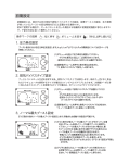
HK S
E L E C T R O N IC S
T E C HNO L O G Y
Instruction Manual
Installation should be performed by a professional.
Prior to installation and use, thoroughly read the
instruction manual. Retain this instruction manual
for later reference.
45003-AK005
HKS USA Inc
Ver.111506
Introduction
HKS EVC
Read this instruction manual prior to installation to ensure safe and correct usage and
optimal product performance,
Product
Use
EVC
Boost Controller- Automotive Turbocharged Engine
Application Vehicle that operates on a DC 12V negative ground.
Part No.
45003−AK005
・A fuel controller (e.g. F-CON, AIC, etc) may be needed when raising boost
pressure with the EVC Boost Controller.
Remarks ・Some vehicles have a fuel cut function when boost is raised. To bypass the
fuel cut function, a unit such as the HKS FCD can be used. When using an
HKS FCD, a fuel controller may be required for additional fuel tuning.
The HKS EVC enables the adjustment of the boost setting from inside the vehicle.
Utilizing a stepping motor, it stimulates boost increase and attains the designated
boost value without over-shooting.
This product was developed to improve engine output and was designed to be used for
racing in a closed circuit. Improving engine output may affect oil and/or water
temperature and oil pressure. To preserve engine performance, regularly monitor
engine conditions before driving.
To use this product on public roads, follow the necessary procedures if there are any
regulations for a tuned/modified vehicle.
●Compact Design
Its compact designed display and stepping motor enables a versatile installation
into the vehicle interior and the engine compartment.
●Wide Boost Range
The boost level can be controlled from baseline boost to 250kPa (36.0PSI).
●Simple Boost Setting
Just directly input the desired boost value to modes A and B, and let HKS EVC
control the boost.
●Return Function
Once EVC is turned off, the boost level returns to the baseline value. For some
vehicles, the boost may become lower than the the stock settings after EVC is off.
●Scramble Function
With the scramble function, the boost can be increased by a designated value above
the set boost value. The increase in boost is obtained while pressing botton① of
the display or the optional external scramble switch (using the provided harness).
The time span of the boost increase after the release of the botton can also be set.
●Dual Boost Mode Settings
A Mode & B Mode are the 2 user specified preset boost level selections. Each mode
can be used for a different purpose or situation.
−1−
●Dual Offset Mode Settings
If the desired set boost and the actual boost levels do not match, the offset
function can be used to adjust for the difference. The offset of both A Mode &
B Mode can be set individually; therefore, more precise results can be obatined.
●Warning Function
If the boost exceeds the user selectable warning value, the EVC notifies the user
with an audiable beep and visable warning display. Simultaneously, it lowers the
boost to the baseline boost value or by a user preset value. This function prevents
damage to the engine and/or the turbine due to over-boost.
●Throttle Position Input
With the throttle position sensor signal input, boost characteristics can be
tuned in relation to throttle percentage.
●RPM Signal Input
With the engine RPM signal input, boost characteristics can be tuned in
relation to RPM level.This feature works on engines from 1 to 8 cylinders and
operates up to 12,000 RPM.
●Speed Signal Input
With the vehicle speed signal input, boost characteristics can be tuned in
relation to vehicle speed. This feature works on applications that utilize speed
pulses between 2 to 16 and has a maximum speed capacity of 500km/h.
●Map Adjustment Function
Input of the throttle signal and the engine RPM or vehicle speed signals can draw a
3D map by using 2 these signals as axes. Using the 3D map enables the easy control
of the boost characteristics.(The setting range must be within +/-120kPa [17.0PSI]
to the baseline boost setting.) This function is user selectable to be on or off.
●Digital Triple Data Meter
3 digital data readings of surge tank pressure, throttle percentage, and engine RPM
or vehicle speed can be displayed.
●Bar Graph Selection
The bar graph display can be set for boost, throttle percentage, engine RPM and
vehicle speed.
●Bar Graph Peak Hold Function
The peak hold function of the bar graph displays and holds the maximum value
achieved for easy instant recognition.
●After Image Display Function
When the boost changes from positive pressure to negative pressure, the maximum
positive boost value is displayed for a few seconds. This function is user
selectable to be on or off.
●Data Memory Function
All set values are saved in the internal memory of the EVC. Therefore, these
settings are not lost when the ignition is off or if the battery is disconnected.
●Exhaust Bypass (wastegate type) Selection
The EVC can work with both internal and external wastegate types.
−2−
●Pressure Unit of Measure Selection
The unit for of measure for pressure can be selected between kPa or PSI.。
●Dimmer Function
The brightness of the display unit is adjustable.
●Data Lock Function
To prevent accidental change of data settings, the unit can be locked with a code
●Large Multi-Display
Utilizing a large positive display enables clear day and night viewing. The multidisplay also enables simultaneous data recognition.
●Digital and Analog Boost Monitoring
The digital data and the bar graph can allow the driver to read and understand the boost
conditions intuitively and visually.
●This manual indicates items you need to pay attention to in order to install this
product safely and lists precautions to avoid any possible damage and/or accidents.
●Please contact your dealer for purchasing consumable parts and lost or missing part.
●To use this product on the public road, follow the necessary procedures if there are
any regulations for a tuned vehicle.
●HKS will not be responsible for any damage caused by incorrect use or use after
modification and/or dismantling of this product.
●To use this product on the public road, follow the necessary procedures if there are
any regulations for a tuned vehicle.
●This product was designed for installation and use on a factory vehicle or a vehicle
using other HKS products. The performance and/or safety cannot be guaranteed if this
product is installed onto other vehicles than mentioned above.
●This product is applicable for any vehicle that operates on a DC12V negative ground.
●The specifications of this product, including installation are subject to change
without prior notice.
●This manual is subject to revise without prior notice.
−3−
Index
Introduction…………………………………………………………………………………………………1
Index …………………………………………………………………………………………………………4
Safety Precautions…………………………………………………………………………………………5
Parts List……………………………………………………………………………………………………8
Features and Functions……………………………………………………………………………………9
Installation…………………………………………………………………………………………………12
Hose Connection Layout…………………………………………………………………………………12
Wiring………………………………………………………………………………………………………23
Mounting of Components…………………………………………………………………………………24
Post Installation Checks…………………………………………………………………………………25
Operation ……………………………………………………………………………………………………26
Optional Parts List ………………………………………………………………………………………44
Maintenance …………………………………………………………………………………………………44
Trouble Shooting……………………………………………………………………………………………45
Product Specifications……………………………………………………………………………………45
EVC Set-Up Sheet……………………………………………………………………………………………47
−4−
Safety Precautions
Below are symbols used in this manual to highlight areas where .
Warning
-Risk of severe injury or death may result if
warning is not acknowledged or followed.
Caution
-Risk of injury to self, damage to vehicle or
property may result if caution is not taken.
Warning
●Make sure to work on the vehilce in a well-ventilated area to prevent
possible explosion or fire.
●Do not mount the unit where it can distract driving.
●Do not install this product on a 24V vehicle. It is designed for use on
a 12V vehicle.
●Make sure to remove the cable from the negative terminal of the battery
to avoid possible damage to other electronics during installation.
●Make sure to hold connectors when removing them to avoid possible
damage to other electronic parts caused by disconnections or by a
short circuit.
●Stop using the product if any unusual conditions are noticed; it may
cause a fire or an electrical shock. Consult an authorized dealer
immediately.
●Do not operate the EVC while driving to avoid the possiblity of an
accident.
−5−
Caution
●Do not install this product by yourself unless you know how to use the
tools and equpiment necessary to safely perform service operations on
your vehicle
●Do not modify, disassemble and/or remodel this product and any of its
attached parts.
●Handle the parts with caution at all times.
●Avoid allowing oil and/or water from entering the unit. It may cause
damage to the engine.
●Prior to installation, make sure that the engine bay temperature has
cooled. Failure to let the engine cool can lead to severe burns.
●Select the appropriate exhaust bypass type. Selecting the wrong type
may cause damage to the vehicle.
●Install the unit away from excessive heat or water to avoid possible
malfunction and damage to the engine.
●Do not tie or bundle a vehicle fuel line with any of the other hoses
and/or harnesses. It may cause severe damage to the vehicle.
●Make sure all connections and wiring are not disconnected, short
circuited or incorrect. It may cause an electrical shock or
damage to the vehicle.
●Used the provided splices and install them to the correct positions. If
not, it may cause serious damage to the vehicle.
●Connect the ground wire onto a good chassis ground. If not, it may
cause damage to the vehicle.
●Insert the vacuum filter and replace it at regular intervals. If not,
it may cause damage to the vehicle.
●When installing the vacuum filter, make sure no oil or lubricants are
existant to cause the hose to come off. If a hose comes off, it may
cause damage to the vehicle.
●Replace the vacuum filter earlier than the regular interval if there
is excessive build up. Dirt build up may cause an inability to control
boost, which may cause damage to the engine.
●Install the air relief valve of the stepping motor downward to avoid
allowing oil and/or water from entering the valve. It may cause
damage to the vehicle.
−6−
Caution
●Do not raise the boost excessively. It may cause damage to the engine
and/or the turbocharger.
●The warning function must be activated to prevent any damage to the
engine caused by over-boosting.
●Do not test the product on the vehicle on a public road.
●If this product or the vehicle does not perform properly, consult your
authorized dealer immediately.
●Do not repair the product by yourself.
●If an unusual noise, smell and/or vibration is noticed, take the
necessary measurements referring to the user's manual.
●Insulate wires left on the vehicle after removal of the product. It
may cause damage to the electronic parts.
●Daily check-up of the vehicle must be done by the owner.
●This manual shows a typical installation. Actual installations may vary depending on
the vehicle application.
●Refer to the factory manual when removing the factory parts.
●Make sure all connections and wiring are correct.
●Do not lose and/or damage any removed parts.
●Use the appropriate tools to tighten bolts and nuts with the correct torque specs to
avoid damage.
●Make sure not to disconnect any wiring from the vehicle when installing the product.
●For a vehicle equipped with a boost control solenoid valve, remove the connector or
hose to deactivate its function.
−7−
Parts List
2.7m
1.5m
1
EVC Display Unit
1
1.0m
5
Power Harness
2
EVC Stepping Motor 3
9
6mm Hose
1.5m
1m
6
7
Scramble Harness
(1 for Speed & RPM,
1 for Throttle signal)
10
2
4mm ,6mm 1 each
T-Fitting
11
3
15
Double-Sided Tape
1
Vacuum Filter
12
S T E C HNOLOG
Hardware Set
操作マ
ークの
ボリュー
パスタ
Pa)
●スクラ
。
イプを
(例:80k ト
Pa)
●ワーニ
最大ブ
EVC取
ースト
付け後の
手動での
を設定
ノーマル
設定を行
する
う場合は 最大ブーストの設
、ボリュ
ームを回 定を行ってくださ
してノー
マル最大 い。
ブースト
を入力し
てくださ
い。
18
設定時間
実際のブース
(例:100 ト
kPa)
エンジン回転
図3.スク
数
ランブル
機能未使
用の場合
スクランブル
開始ポイント
ブース
ト
Instruction Manual
1
kPa)
実際のブース
(例:100 ト
kPa)
ングとは
スクランブル
ワーニ
ブースト設定
ングと
(例:20k 値
?ドロッ
画面お
は、設
Pa)
エンジン回転
図4.スク
よび音
定した
数
プブース
ドロッ
ランブル
で警告
ワーニ
プブー
機能使用
をする
ングブ
ップブ
トとは?
ストと
の場合
ースト
ととも
ースト
は、ワ
に対し
に目標
ドロッ
OFF
ーニン
て実際
ブース
プブー
ではノ
グ作動
のブー
トを下
んので
スト設
ーマル
時に目
ストが
げる機
注意し
定モー
ブース
標ブー
その値
能です
てくだ
ドで設
トに下
を超え
ストの
。
さい。
定した
がりま
た場合
下げ幅
ブース
す。
に、
を決定
ワーニングブ
ト値に
できる
ースト(例:
、実際
機能で
120kPa
のブー
す。ド
)
ストが
ロ
目標ブースト
なるわ
(例:100
けでは
kPa)
ノーマルブー
ワーニングブ
ありま
(例:60k スト
(例:120 ースト
せ
実際のブース
Pa)
kPa)
3.ノ
ーマル
(例:60k ト
Pa)
図5.ドロ
数
ップブー
ワーニン
ストOF
グ作動時
Fの
エンジン回転
。
目標ブースト
(例:100
ドロップブー
実際のブース
kPa)
(例:20k スト設定値
(例:80k ト
Pa)
Pa)
図6.ドロ
数
ップブー
ワーニン
スト設定
グ作動時
後の
エンジン回転
E051
21−K
Ver.
000?
3−1.
?−00
01
E0512
1−K00
Ver.
0??−0
3−1.
01
0
17
図1.オフ
エンジン回転
セット1
数
00%の
場合
ンブ
スクラ
ルブース
ンブル
ブース
ブース
トとは?
図2.オフ
トを一
トとは
エンジン回転
スクラ
定時間
セット1
、Aモ
数
ンブル
プラス
20%の
ードま
ません
ブース
ことが
場合
たはB
ので注
ト設定
できる
モード
意して
モード
機能で
で設定
くださ
で設定
す。
した目
い。
したブ
標ブー
ースト
ストに
目標ブースト
値に、
対して
(例:80k
実際の
、設定
Pa)
ブース
した
トがな
るわけ
目標ブースト
ではあ
(例:80k
スクランブル
り
Pa)
実際のブース
ムを回し
アクチュ
設定す
て排気バ
エータを
る
イパスタ
するポペ
使用する
ットバル
スイング イプの設定を行っ
設定が終
ブタイプ
バルブタ
了したら
の場合「
イプの場 てください。
ボリュー
ーPー]
合「ーS
ムを押し
を選択し
−」を、
て決定し
てくださ
ウエスト
てくださ
い。
ゲートを
い。
使用
。
ット
オフセ
とは?
ットと
圧になら
は、A
モード
オフセ ない場合に、値を または
ット値
Bモー
がりま
調整する
を上げ
ドで設
す。排
ると実
定した
ことによ
この関
気バイ
際のブ
目標ブ
係性は
パスタ
ースト って目標
変わり
ブースト ーストに対し
イプが
は上が
ません
スイン
り、オ
に安定さ
て実際
。
グバル
フセッ
せること のブー
目標ブースト
ブタイ
ト値を
(例:100
ができる ストがその
プ、ポ
下げる
kPa)
機能です
ペット
と実際
バルブ
のブー
。
タイプ
ストは
のどち
下
らでも
実際のブース
目標ブースト
(例:80k ト
、
(例:100
:ボリ
ューム
ブース
ト
った後も、本製品
ご使用中にわから
の側に置いてご活
ないことや、不具
用ください。
合が生じた際に便
利です。
操作クイ
ックマニ
:短く
ュアル
押す
EVC機
能解説
ブース
ト
取付けは、必
ず専門業者に
依頼してくだ
取付け前及び
さい。
ご使用前に必
ずお読みにな
ってください
本書はお読みにな
21207-023T
1998年○月○日発行
Ver.3-1.0
1Set
●オフセ
ブース
ト
った後も、本製品
ご使用中にわから
の側に置いてご活
ないことや、不具
用ください。
合が生じた際に便
利です。
Tie Wrap
ブース
ト
った後も、本製品
ご使用中にわから
の側に置いてご活
ないことや、不具
用ください。
合が生じた際に便
利です。
取付けは、必
ず専門業者に
依頼してくだ
取付け前及び
さい。
ご使用前に必
ずお読みにな
ってください
本書はお読みにな
。
った後も、本製品
ご使用中にわから
の側に置いてご活
ないことや、不具
用ください。
合が生じた際に便
利です。
16
ション
を回す
エンジン
スイッ
キーを回
:1秒
がないこ
チを"
してイグ
以上押
とを確認
ON"
ニッショ
し続け
してくだ
にする
ンスイッ
る
さい。問
チを"O
題がなけ
N"にし
を設定
ればその
てEVC
初めて使
および車
ままエン
する
用する場
両から異
ジンをか
ボリュー
合は、自
音・異臭
けてくだ
ムを回し
設定が終
さい。
てブース 動的に下図のよう
了したら
ト表示の
ボリュー
圧力単位 な画面が表示され
ムを押し
をPAS
て決定し
(kPa ています。
てくださ
)または
PSIか
い。
ら選択し
てくださ
い。
2.排
気バイ
取付けは、必
ず専門業者に
依頼してくだ
取付け前及び
さい。
ご使用前に必
ずお読みにな
ってください
本書はお読みにな
100mm…………Qty.5
2.圧
力単位
R
取付けは、必
ず専門業者に
依頼してくだ
取付け前及び
さい。
ご使用前に必
ずお読みにな
ってください
本書はお読みにな
2
説明
1.イ
グニッ
車種別配線位
置図
Y
V ALV E C ONT
R OLLE
Hose Clamp
ブース
ト
HK S E LE C T T
R ONIC
1
1Set
取付けは、必
ず専門業者に
依頼してくだ
取付け前及び
さい。
ご使用前に必
ずお読みにな
ってください
取付けは、必
。
ず専門業者に
依頼してくだ
取付け前及び
さい。
ご使用前に必
ずお読みにな
ってください
。
E LE C T R ONIC
4mm Hose
1801-SA033
6mm……4599-RA016
4mm……4599-RA017 1Set
1
14
Splice
1m
φ6用
M6Bolt and Nut
M6Flat Washer
M6Lock Washer 1 each
13
1
Input Signal Harness 8
1
1
Extension Harness
1
4-4-4mm
1801-SA004
4
1
1
1m
Main Harness
Connecting Manual
1
19
20
Quick Manual
1
Function Manual
1
● Tools required for installation: Test Light or Volt Meter, Screwdriver, Socket Wrench,
Wire Cutters, Hose Cutters and Pliers.
● Retain all unused parts.
−8−
Features and Functions
1. Features
1.Button ①
Front
Panel
2.Volume Knob
3.Button ②
4.Main Harness Connector(3PIN)
Rear
Panel
5.Scramble Harness Connector(2PIN)
6.Easy Writer Connector(5PIN)
1.Button ①
Use this button to activate the scramble function in the standard mode. While pressing
this button, the scramble function is activated. When the scramble function's timer is
set,the function starts working when the button is released. If the set value is blinking
in the speed axis set mode, RPM axis set mode, throttle axis set mode, map correction
boost A/B set mode, or map offset A/B set mode, this button is used to select between the
set axis and the set value.
2.Volume Knob
In the standard mode, pressing the volume knob for more than 1 second resets the peak
value. Turn the knob left to switch to boost mode A and turn right to the mode B.
Pressing the volume button in each mode makes the set value blink or turn it on. When
the set value is blinking, turning the volume knob to the right increases the value; and
turning it to the left decreases the value. In other modes (aside from standard mode),
when the value is blinking, turning the button switches the modes in each mode group.
3.Button ②
In the standard mode (when the A/B boost value is not being set) press this button for
more than 1 second to switch the EVC on or off. When the power is on, the EVC control
becomes active. When the power is off, the vehicle returns to the standard boost value
which is not controlled by the EVC. When the set value in each mode is blinking,
pressing this button switches the mode group.
4.Main Harness Connector
This main harness connects the power harness, extension harness, and each signal harness.
5.Scramble Harness Connector
This scramble harness connects the optional external scramble switch.
6.Easy Writer Connector
This connector is for PC communication to make settings with the HKS Easy Writer. (Optional)
−9−
2.Display
2.1.Digital Display
1.Digital Display (S)
2.Speed / RPM Display
3.Throttle Display
6.Indicator Display
4.Unit Display
7.Bar Graph Display
5.Digital Display(L)
8.Selection Display
1.Digital Display(S)
In this display, the preset warning value, preset A/B boost values, scramble
countdown time, mode name, or wastegate type is shown. The pressure is shown as
○○○(kPa) or ○○.○(PSI), the scramble countdown time is shown as ○○(Sec), the
mode name is shown as ○○○(MODE), and the wastegate type is shown as −○−.
Standard Mode
:Set Warning Value
Standard Mode(A/BBoost Settings)
:Preset A/BBoost Values
Standard Mode(Scramble Function)
:Scramble Countdown Time
Each Setting Mode
:Mode Name
Opening Screen
:Wastegate Type
2.Speed / RPM Display
In this display, the value for each axis of the following mode is shown; Speed Axis
Set Mode, RPM Axis Set Mode, Map Correction Boost A/B Set Mode and Map Offset A/B
Set Mode.
3.Throttle Display
In this display, the value for each axis of the following mode is shown; Throttle Axis
Set Mode, Map Correction Boost A/B Set Mode, and Map Offset A/B Set Mode.
4.Unit Display
In this display, the 4 units of measure(kPa, PSI, S, V) are shown for each mode:
kPa is displayed for manifold pressure
PSI is displayed for manifold pressure
S is displayed in the Scramble Time Set Mode
V is displayed in the Full Throttle Voltage Set & Closed Throttle Voltage Set Modes
5.Digital Display(L)
In this display, the manifold pressure, set value, or name is shown as ○○○(kPa) or
○○.○(PSI):
In the Standard Mode the boost value is shown
In each Set Mode, the set value or mode name is shown
6.Indicator Display
This display shows the following:
In the Standard Mode and the peak value is displayed, "P.H." is iluminated.
In the Standard Mode and the map function is being used or in the Map Set
Group, "MAP" is iluminated.
In each mode where the set value is being changed, "SET" is illuminated.
In each mode where the set value is being selected, "SEL" is illuminated.
In the Scramble Boost Set Mode, Scramble Time Set Mode, or if the scramble function
is activated, "SBC" is illuminated.
In the Warning Boost Set Mode, Drop Boost Set Mode, or if the warning function is
activated, "WRN" is illuminated.
−10−
7.Bar Graph Display
In this display, a bar graph of the following can be shown: manifold pressure, speed,
RPM, throttle percentage opening, set value, or axis number. In the Standard Mode, you
can select between the manifold pressure, speed, RPM, and throttle percentage opening
for real-time display.
8.Selection Display
The indicators of A and B show the selected preset boost setting in the Standard Mode.
In the Offset A/B Set Mode, Map Boost A/B Set Mode and Map Offset A/B Set Mode, the
current preset value is shown. The indicator of SPD, REV, and THR show the input signal
currently used for the correction map in the Standard Mode, Map Boost A/B Set Mode and
Map Offset A/B Set Mode. In the Speed Axis Grid Point Set Mode, RPM Axis Grid Point
Mode and Throttle Axis Grid Point Set Mode, each corresponding signal is shown.
2.2.Start-Up
After the unit beeps once, the
wastegate type appears on the digital
display (S), and the preset boost value
appears on the digital display (L).
Beep
2.3.Scramble Boost Activated
..
ep..
eee
Beee
After the unit beeps, the bar graph
and the SBC indicator will blink.
2.4.Warning Function Triggered
.
p...
pBee
Bee
Beep
After the unit beeps, the bar graph and
the WRN indicator will blink.
Note
・The LCD of the display unit may have a black line. This is caused by static electricity,
and it does not affect the functions or performance of the unit. To remove the line,
wipe the display with an antistatic cloth or a cloth with the antistatic solution.
−11−
Installation
1. Removal of Battery Terminal
…………………………………………………………………… 12
2. Hose Connection Layout
2.1. Stepping motor and 4mm Hose ……………………………………………………………
2.2. Swing Valve Type …………………………………………………………………………
2.3. Poppet Valve Type …………………………………………………………………………
2.4. Twin Turbo(Swing Valve) ………………………………………………………………
2.5. 4mm Hose Connection Layout(Swing Valve) …………………………………………
3. Wiring
13
14
18
20
21
……………………………………………………………………………………………… 23
4. Mounting of Components …………………………………………………………………………… 24
5. Post Installation
………………………………………………………………………………… 24
Warning
●This product was designed to be used with vehicles using a DC12V
negative ground. Do not use on a vehilce with a 24V ground.
●This manual shows a typical installation.
the vehicle application.
Actual installation may vary depending on
1.Removal of Battery Terminal
(1)Disconnect the negative terminal from the battery.
2.Hose Connection Layout
(1)With consideration to the hose and harness lengths, determine the appropriate hose
connection layout and mounting in regards to the display unit and stepping motor.
Advice
・Leave some slack for the harness & hoses to avoid tension during engine movement.
・Do not install any components in high temperature areas.
−12−
2.1.Stepping Motor and 4mm Hose
(1)Cut the 4mm and 6mm Hose and connect them
to the respective 4mm and 6mm vacuum
filters as shown in the diagram on the left.
Advice
・Cut the 4mm and 6mm hose to different
lengths so that the vacuum filters are
not in contact with each other.
・Do not pu any oil and/or lubricants on
or in the hose and vacuum filter.
6mm Vacuum Filter
4mm Vacuum Filter
4mm Hose
5cm Length
6mm Hose
8cm Length
Hose Clamp
(2)Remove the hose that connects the intake
manifold and the fuel pressure regulator
from intake manifold side.
Remove Here
Intake
Manifold
4mm Hose
Fuel
Pressure
Regulator
(3)Cut a 5cm length portion of the included
4mm hose and connect it the the T-Fitting
as shown in the diagram on the left.
4mm Hose
5cm Length
Intake
Manifold
4mm Hose
4x4x4 mm
T- Fitting
Fuel Pressure
Regulator
4mm Vacuum Filter
NippleB
(4)Use the remaining 4mm hose to connect the
T-Fitting to 4mm vacuum filter on Nipple B
of the EVC Stepping Motor.
Advice
・Make the hose length short as possible
・Do not put and oil and/or lubricants on
or in the hose and vacuum filter
Fuel Pressure
Regulator
・Nipples of the EVC stepping motor must be
facing upward to avoid any oil or water
from entering.
4x4x4mm
T-Fitting
Intake
Manifold
4mm Hose
EVC Stepping Motor
−13−
2.2.Swing Valve Type
2.2.1.For Applications without a Boost Solenoid Valve
Before Installation(Basic Connection Layout)
Airflow Meter
Turbine
Compressor
Nipple①
Actuator
Air Filter
Throttle Valve
Intake
Manifold
6mm Hose
Fuel Pressure
Regualtor
After Installation
Airflow Meter
Turbine
Compressor
Nipple①
Actuator
Air Filter
Throttle Valve
Intake
Manifold
6mm Hose
4x4x4 mm
T-Fitting
6mm Hose
Vacuum Filter
Fuel Pressure
Regulator
4mm Hose
EVC Stepping Motor
−14−
Hose Clamp
Hose Clamp
Nipple①
(1)Remove the hose which connects the actuator
and Nipple① from the compressor side.
Note
・The position of Nipple① on the compressor
may vary depending on vehicle.
・Reuse the factory hose clamp.
Actuator
6mm Hose
6mm Vacuum Filter
Hose Clamp
Nipple①
(2)Connect Nipple① and the EVC Stepping
Motor's 6mm vacuum filter using the
included 6mm hose.
EVC Stepping
Motor
(3)Connect the factory hose, which is still
connected to the actuator, to the EVC
Stepping Motor's NippleO.
Hose Clamp
NippleO
Factory 6mm Hose
Advice
・Do not put any oil and/or lubricants on or in the hose and vacuum filter.
・Use the hose clamp to connect the 6mm hose and the 6mm vacuum filter.
・If the factory hose's length is not long enough to connect, use the optional
oil-resistant hose. This optional oil-resistant hose is available separately.
(Refer to the Optional Parts list in this manual)
−15−
2.2.2.For Applications with a Boost Control Solenoid - 1
●Bypass the function of the boost control solenoid valve by removing the connector or
hose.
Before Installation(Basic Connection Layout)
Airflow Meter
Turbine
Compressor
Actuator
Air Filter
Throttle Valve
Boost Control
Solenoid Valve
Intake
Manifold
6mm Hose
Fuel Pressure
Regulator
After Installation
Rubber Cap
Airflow Meter
Turbine
Boost Control
Solenoid Valve
Compressor
Actuator
Air Filter
Throttle Valve
Intake
Manifold
Rubber Cap
6mm Hose
4x4x4 mm
T-Fitting
6mm Hose
Vacuum Filter
Fuel Pressure
Regulator
4mm Hose
EVC Stepping Motor
−16−
2.2.3.For Applications with a Boost Control Solenoid Valve - 2
●Bypass the function of the boost control solenoid valve by removing the connector or
hose.
Before Installation(Basic Connection Layout)
Airflow Meter
Turbine
Compressor
Actuator
Air Filter
Throttle Valve
Intake
Manifold
6mm Hose
Boost Control
Solenoid Valve
Fuel Pressure
Regulator
After Installation
Rubber Cap
Airflow Meter
Turbine
Compressor
Actuator
Air Filter
Rubber Cap
Throttle Valve
6mm Hose
Boost
Control
Solenoid
Valve
Intake
Manifold
4x4x4 mm
T-Fitting
6mm Hose
Vacuum Filter
Fuel Pressure
Regulator
4mm Hose
EVC Stepping Motor
−17−
2.3.Poppet Valve Type
To install this unit on to a poppet valve equipped vehicle, the hose set for the poppet
type is necessary.
Before Installtion
Airflow Meter
Turbine
Upper Port
Compressor
Air Filter
Throttle Valve
Intake
Manifold
8mm Hose
Wastegate
Fuel Pressure
Regulator
After Installation
Airflow Meter
Turbine
Wastegate
Compressor
Attach nipple
(L or straight nipple)
to upper
Air Filter
6x8x6mm T-Fitting
port
Throttle Valve
6mm Hose
Intake
Mainfold
4x4x4 mm
T-Fitting
6mm Hose
Vacuum Filter
6mm Hose
Fuel Pressure
Regulator
4mm Hose
EVC Stepping Motor
−18−
Nipple①
Cut Here
5cm Length
Wastegate
Nipple①
Hose Clamp
6x8x6 mm T-Fitting
(1)Cut the 8mm hose at the point of 5cm from
the compressor's Nipple①. Remove the
remaining 8mm hose and 8mm nipple from the
wastegate.
Note
・The position of Nipple① on the compressor
may vary depending on the vehicle.
(2)Install the 6x8x6mm T-Fitting using the 8mm
Hose Clamp.
Note
・Use the 6x8x6mm T-Fitting and 8mm Hose
Clamp included in the hose kit for the
poppet valve type applications.
(3)Connect the 6mm Vacuum Filter of the EVC
Stepping Motor's NippleⅠ to the T-Fitting
using the 6mm hose.
Advice
・Do not put any oil and/or lubricants on
or in the hose or vacuum filter.
Hose
Clamp
6mm Hose
6mm Vacuum Filter
NippleⅠ
(4)After removing the 8mm nipple from the
wastegate, install the 6mm nipple (straight
or L-Shaped).
(5)Install the included 6mm hose as shown in
the diagram on the left.
Hose Clamp
6mm Hose
6mm Nipple
Note
・Use the hose clamp to connect the 6mm hose and the 6mm nipple.
−19−
6mm Nipple
(6)Install the 6mm nipple to the wastegate's
upper port.
(7)Using 6mm Hose, connect the EVC Stepping
Motor's NippleO to the 6mm nipple installed
on the wastegate in step #(6).
6mm Hose
NippleO
2.5.Twin Turbo Applications (Swing Valve Type)
To install this unit on to a twin turbo vehicle, the hose set for the twin turbo
vehicle is needed. The basic hose layout procedure is similar as the swing valve.
(1)Remove the factory hoses between each
turbocharger's compressor and actuators.
Remove These
Actuators
IN
IN
EX
(2)Connect the actuators of each of the two
turbochargers using 6mm hose.
(3)Connect each compressor of the two
turbochargers using 6mm hose.
6mm Hose
Advice
・Use the 6mm hose and 6mm hose clamps.
Actuators
IN
IN
EX
6mm Hose
(4)Cut the center of each of the 6mm hoses and
and insert a 6x6x6 T-Fitting in each.
Advice
・Use 6mm hose clamps to secure hoses.
6mm Hose
6x6x6 mm
T-Fitting
Actuator
IN
IN
EX
−20−
(5)Follow the instructions of Section 2.2 Swing Valve Type for remaining steps.
EVC Stepping Motor
4mm Hose
6mm
Vacuum Filter
4mm Vacuum Filter
6mm Hose
IN
IN
EX
Twin Turbo Application Sample
2.5.4mm Hose Layout Application
To install this unit on a 4mm hose equipped vehicle, the 4mm hose set is needed.
The basic hose layout procedure is the same as for the swing valve type.
Airflow Meter
Turbine
Compressor
Actuator
4mm→
←6mm Hose
Adapter
Air Filter
Throttle Valve
4mm Hose
6mm Hose
Vacuum Filter
6mm Hose
Intake
Manifold
4x4x4
T-Fitting
4mm Hose
4mm←6mm Hose
Adapter
Fuel Pressure
Regulator
4mm Hose
EVC Stepping Motor
(1)Use the 4mm hose included in the 4mm hose set instead of the included 6mm hose on
points where the 6mm hoses are supposed to be used.
(2)Connect the 6mm hose to the 6mm vacuum filter using the 4mm-6mm adpater included
included in the 4mm hose set.
Advice
・Use the 6mm hose included in this product.
・Do not put any oil and/or lubricant on or in the hose and the vacuum filter.
−21−
∼MEMO∼
−22−
3.Wiring
3.1.Installing Splices
①Strip 5mm of the wiring insulator for wiring.
Strip 5mm of cover
②Connect another wire to the uncovered
portion by twisting the wires together.
Twist wires together
③Stake the twisted wires using a splice.
Stake the wires
using a splice
④Cover the splice and wires with
electrical tape to insulate.
Insulate with
electrical tape
3.2. Wiring
Vehicle Interior
Engine Compartment
EVC Display Unit
EVC Stepping Motor
Throttle Input Signal (Blue)
Speed / RPM Input Signal (White)
5 PIN Connector (White)
4 PIN Connector (White)
Main
Harness
Power Harness
Extension Harness
5 PIN Connector
(Black)
Scramble Harness
(1)Pull the white connector of the Extension Harness from the engine compartment into
the vehicle interior and connect it to the 5 PIN connector of the EVC Main Harness.
(2)Connect the Extension Harness to the 5 PIN Connector of the EVC Stepping Motor.
(3)Connect the EVC Main Harness to the 3 PIN Connector of the Display Unit.
(4)Connect the red wire of the Power Harness to the ignition wire using a splice.
(a)Reconnect the negative battery cable to the battery terminal.
(b)Turn the ignition switch on and find the wire generating 12v using a test light.
(c)Remove the negative battery cable from the terminal of the battery.
(5)Confirm the locations of the throttle signal line and the engine RPM signal line or
the speed signal line of the vehicle's harness that connects to the ECU. Connect
the blue wire of the Input Signal Harness to the throttle signal line, and the white
wire to the engine RPM signal line or the speed signal line using splices. Refer to
the factory service manual for signal line locations.
Advice
・If a speed limiter release device such as the HKS SLD is already installed on
the vehicle, connect the white wire of the input signal harness to the side towards
the vehicle's harness from the device.
・Do not connect unused signal lines.
(6)Connect each input signal wire to the same colored wires on the Main Harness.
(7)Connect the ground wire (Black).
−23−
Advice
・Rub off any paint and/or rust of the surface where the ground wire is connected.
(8)Connect the 4 PIN Connector of the Main Harness to the Power Harness.
Note
・When utilizing an external switch for the Scramble Boost activation, connect the
two wires (blue and white) of the scramble harness to a momentary switch in the
form that when the switch is triggered a closed-circuit is made.
4.Mounting of Components
4.1.Mounting the Display Unit
EVC Display Unit (Rear)
Double-Stick Tape
(1)Remove any dirt, dust and/or oil from the
area the unit is going to be mounted to.
(2)Secure the display unit using the included
double-side tape.
Advice
・The display was designed to have the best
visibility when it is looked at downward.
It is recommended to mount the display unit
to a position where it is lower than your
eyes or mount the unit facing upwards.
4.2.Mounting the Stepping Motor
(1)Mount the Stepping Motor using the M6
bolt and nut.
Nipple
EVC Stepping Motor
M6
4.3.Securing the Hose and Harness
(1)Secure hoses and harnesses using the included tie-wraps.
Advice
・Leave slack in the hose and harness to absorb engine vibration and movement.
5. Post Installation
(1)Reinstall all removed factory parts.
(2)Reconnect the negative battery cable to the battery terminal.
−24−
Post Installation Checks
Check the following after the installation processs is complete.
1.
Check the following BEFORE starting the engine
Items to check
Checked
Make sure all hoses are routed and connected correctly.
Make sure all hoses do not have too much slack.
Make sure all hoses are not damaged.
Make sure all hose clamps are secure and tight
Make sure all bolts and nuts are properly tightend.
Make sure hoses, harnesses & installed components do not contact other parts.
Make sure hoses and harnesses are secured properly.
Make sure wiring is done correctly.
Make sure all connectors and splices are connected securely.
Make sure all splices are the included ones and stalked properly.
Make sure the unit or components are mounted securely and dont disturb driving.
Make sure the negative cable terminal is securely attached to the battery.
Make sure the boost control solenoid valve is bypassed.
2.
Check the following AFTER starting the engine
Advice
・Do not raise the engine RPM right after staring engine. (Let it idle)
Items to check
Checked
Make sure there is no air leakage.
Make sure there is no air leakage after revving the engine in neutral 2-3 times.
Make sure installed parts are not in contact with each other.
Make sure there is no excessive stress on hoses or harnesses.
Make sure there are no parts that have loosened after stopping the engine.
−25−
Operation
1. Operation Outline ……………………………………………………………………………………27
2. Initial Set-Up…………………………………………………………………………………………29
3.
Standard Mode
3.1. Boost Control ……………………………………………………………………………… 31
3.2. Peak Hold …………………………………………………………………………………… 31
3.3. Scramble …………………………………………………………………………………… 31
4. Basic Settings Group
4.1. Offset A Set Mode / Offset B Set Mode ……………………………………………
4.2. Scramble Boost Set Mode …………………………………………………………………
4.3. Scramble Time Set Mode……………………………………………………………………
4.4. Warning Boost Set Mode……………………………………………………………………
4.5. Drop Boost Set Mode ………………………………………………………………………
32
32
32
33
33
5. Map Setting Group
5.1. Map Functions Set Mode……………………………………………………………………
5.2. Speed Axis Grid Point Set Mode…………………………………………………………
5.3. RPM Axis Grid Point Set Mode……………………………………………………………
5.4. Throttle Axis Grid Point Set Mode ……………………………………………………
5.5. Boost Map Correction A Set Mode / Boost Map Correction B Set Mode ………
5.6. Offset Map A Set Mode / Offset Map B Set Mode …………………………………
34
34
35
35
36
37
6. Function Setting Group
6.1. Bar Graph Function Set Mode ……………………………………………………………
6.2. Bar Graph Maximum Value Set Mode………………………………………………………
6.3. Backlight Brightness Set Mode …………………………………………………………
6.4. After Image Set Mode………………………………………………………………………
6.5. Bar Graph Peak Set Mode …………………………………………………………………
6.6. Data Lock Set Mode…………………………………………………………………………
38
38
39
39
40
40
7. Vehicle Setting Group
7.1. Cylinder # Set Mode ………………………………………………………………………
7.2. Speed Pulse Set Mode………………………………………………………………………
7.3. Throttle-Off Voltage Set Mode …………………………………………………………
7.4. Full Throttle Voltage Set Mode…………………………………………………………
7.5. Sampling Rate Set Mode……………………………………………………………………
7.6. All Reset Mode………………………………………………………………………………
41
41
42
42
43
43
−26−
1.Operation Outline
Ignition ON
(Ref. page 29)
Initial Set-Up
First Use / After All Reset
Standard Mode
Post Initial Set-Up
(Ref. page 31)
A Mode
B Mode
Turn Knob
Target Boost Setting:
①
or External Scramble Switch
Short
Power ON/OFF: ②
Peak Value Reset:
Long
Long
②
Short
②
Short
Offset A Set Mode
②
Map Function Set Mode
Turn
Turn
Offset B Set Mode
Speed Axis Grid Point Set Mode
Turn
Turn
Scramble Boost Set Mode
RPM Axis Grid Point Set Mode
Turn
Turn
Scramble Time Set Mode
Throttle Axis Grid Point Set Mode
Turn
Turn
Warning Boost Set Mode
Boost Map Correction A Set Mode
Turn
Turn
Drop Boost Set Mode
Boost Map Correction B Set Mode
Turn
Offset Map A Set Mode
Turn
Offset Map B Set Mode
Basic Setting Group
Map Setting Group
(Ref. page 32)
(Ref. page 34)
−27−
Short
Button①
Volume Knob
Button②
※Operational Diagram
① :Button①
② :Button②
:Volume Knob
Scramble
After Scramble Countdown
②
②
Bar Graph Function Set Mode
Short
Short
Cylinder # Set Mode
Turn
Turn
Bar Graph Max Value Set Mode
Speed Pulse Set Mode
Turn
Turn
Backlight Brightness Set Mode
Throttle-Off Set Mode
Turn
Turn
After Image Set Mode
Full Throttle Set Mode
Turn
Turn
Bar Graph Peak Set Mode
Sampling Rate Set Mode
Turn
Turn
Data Lock Set Mode
All Reset Mode
Function Setting Group
Vehicle Setting Group
(Ref. page 38)
(Ref. page 41)
−28−
2.Initial Set-Up
Initial Set-Up Configuration: unit of measure for pressure, wastegate type,and target
boost. The characteristics of the boost change for each vehicle can be memorizedby the
EVC. When using the EVC for the first time (or after a reset) the initial set-up will
be automatically started. Follow the procedure below for the initial setting.
Action Key
:Press
:Turn Volume
:Press and hold for 1 sec.
2.1.Setting the Pressure Unit of Measure
(1)Turn the volume knob and select the pressure unit of
measure from "PAS (kPa)" or "PSI."
・The digital display (S) will display "
".
(2)Press the volume knob after selecting the unit, Go to
2.2 for setting the exhaust bypass (wastegate) type.
2.2.Setting the Exhaust Bypass Type
For most factory turbo applications, the actuator type is used; therefore, the exhaust
bypass type is the swing valve type. For most large capacity turbo applications, the
external wastegate is used; therefore, the exhaust bypass type is the poppet valve type.
(1)Turn the volume knob and select the exhaust bypass
type from "-S-" for the swing valve type or "-P-" for
the poppet valve type.
・The digital display (S) shows " ".
(2)Press the volume knob after selecting the exhaust
bypass type. Go to 2.3 for setting the standard max
boost setting.
2.3.Setting the Standard Maximum Boost Setting
The maximum baseline/default boost after installing the EVC.
(1)Turn the volume knob and set the max baseline /
default boost value if the boost value is known.
If not, drive the vehicle under load to achieve the
maximum boost value. The value will then be shown
in the digital display (S).
・The speed/RPM display shows " ".
・The digital display (L) shows the current boost
value.
・Enter the max boost value that is stable.
(2)Press the volume knob when the digital display (S)
is showing the max baseline/default boost value.
Go to 2.4 for setting the target boost.
−29−
2.4.Setting the Target Boost
Set the target boost level desired
(1)Turn the volume knob to select the desired target boost value.
・The digital display (S) shows "
".
・The target value is for both A & B boost settings.
・Changes to target boost for both A & B modes can made
in the Standard Mode after completing the initial
setting.
(2)Press the volume knob after setting the target boost.
Go to 2.5 for setting the correction coefficient.
2.5.Setting the Correction Coefficient
If the target cannot be achieved, increase or decrease the correction coefficient to adjust
the boost to the target value.
(1)Ensure the display is as shown in the illustration
on the left. Drive the vehicle to reach the max
boost. If the target boost and the actual max boost
do not match, turn the volume until the actual max
boost reaches to the target boost.
・The speed/RPM display shows "
".
・Increasing the correction coefficient raises boost
and decreasing the coefficient reduces boost.
・The digital display(S) shows the peak hold value
and the digital display (L) shows the current
boost value.
(2)Press the volume knob after setting the coefficient.
This completes the initial setting.
Go to 3 for the standard mode.
Note
・For the vehicle equipped with the boost solenoid valve, after installing the EVC, the
standard max boost will be lower than the boost before installing the EVC.
・In the below cases, the max boost cannot reach 250kPa:
(a)The set load (spring's force) of the wastagate's valve or actuator is too low.
(b)The exhaust back pressure is creating a resistance.
・In the below cases, the boost cannot be stabilized:
(a)Wastegate's valve area and/or its stroke in not sufficent. Or, the boost creep or
drop is due to the actuator incapacity.
(b)Turbo air volume is not sufficent for the engine displacement. Or, the boost creep
or drop is due to an increase in the exhaust pressure.
Therefore, conditions and specifications of the vehicle must be examined carefully
before installing the EVC.
・Refer to the following procedures for the setting range of each value.
B
o
o
s
t
B
o
o
s
t
RPM
Stable Boost
−30−
RPM
3.Standard Mode
3.1.Boost Control
Set the boost values for A/B modes in the Standard Mode.
(1)In the Stanards Mode, press the volume knob to set
・The EVC will beep and P.H.will illuminate; the
digital display (S) changes from peak hold display
to the blinking target boost value.
・"SET" will also illuminate.
・To set value for B Mode, select B Mode with the
volume knob (turn right), then press knob.
(2)Turn the volume knob to set the target boost value.
When the value is selected, press the volume knob again.
・The EVC will beep and the displays returns to peak
hold display.
・The selection range is from baseline boost to
250kPa / 36.0 PSI.
・The target boost value set in the initial setting is
the default value for booth A & B Modes.
(3)To turn the EVC off, press Button② for more than 1
second. Repeat set to turn the EVC on.
・An audible beep will be emitted to confirm action.
・When the EVC is off, the current boost reading and the
Peak Hold value will be the only data displayed.
3.2.Peak Hold
While the EVC is in the Standard Mode, the maximum boost is displayed and automatically
updated in the digital display (S), denoted with the P.H illumination. To reset value:
(1)Press the volume knob for more than 1 second
・The peak hold value will cleared and reset to
0 kPa or 0.0 PSI accordingly.
3.3.Scramble
Activate the Scramble boost function by pressing Button① or the external scramble switch.
(1)After pressing Button① or the external scramble
to trigger its activation, the EVC will.
・Beep to indicate that the function is active.
・The bar graph and "SBC" will blick and the remaining
time of the scramble will be displayed on the digital
display (S).
・When using the user preset time function of the
Scramble, the countdown does not begin until the
release of the button or external switch.
−31−
4.Basic Settings Group
4.1.Offset A Set Mode / Offset B Set Mode
Adjust the boost's gain or stability for both A and B Modes.
(1)Press the volume knob in the Offset A Set Mode or
Offset B Set Mode.
・The digital display (S) will display [
].
・The EVC will beep and the digital display (L) blinks.
・"SET" will appear in the display.
・The left illustration references Offset A Set Mode.
(2)Turn the volume knob and set the Offset A and B value.
When the settings are done, press the volume knob.
・The setting range is between 1-199% in 1% increments.
・The default setting value is 100%.
・The boost will rise when the set value is increased
and vice versa. This applies to both wastegate
type selections.
4.2.Scramble Boost Set Mode
Set the boost value to be added to the target boost when the Scramble function is triggered.
(1)Press the volume knob while in the Scramble Boost Set
Mode.
・Digital Display (S) will illuminate [
].
・"SBC" will be illuminated on the display.
・The EVC will beep and the digital display (L) blinks.
・"SET"will be illuminated on the display.
(2)Turn the volume knob to select the amount of additional
boost for the Scramble function. After the selection,
press the volume knob to set.
・The setting range is between 0-120 kPa or 0.0-17.0 PSI
respectively for the unit of measure selected.
・The default setting is 0 kPa or 0 PSI.
4.3.Scramble Time Set Mode
Set the time duration of the added Scramble boost for when the Scramble is triggered.
(1)Press the volume knob while in the Scramble Time Set Mode.
・The digital display (S) will illuminate [
]
・"SBC" will be illuminated on the display.
・The EVC will beep and the digital display (L) blinks.
・"SET"will be illuminated on the display.
−32−
(2)Turn the volume knob to select the duration of Scramble
Time. After selection is done, press the volume knob.
・The setting range is between 0-60 seconds in 1 second
increments.
・The default setting is 0 seconds.
Note
・While pressing Button①, the Scramble function is activated. However, the Scramble timer
function will not countdown until after the release of the button. When the Scramble time
is set to 0 second, the Scramble function is only active when the button is pressed.
4.4.Warning Boost Set Mode
The warning function is activated when the manifold pressure goes exceeds the user preset
boost value. The EVC will drop boost to baseline boost or by a user set amount of boost.
(1)While in the Warning Boost Set Mode, press the volume
knob.
・The digital display (S) will illuminated [
].
・"WRN" will be illuminated on the display.
・The EVC will beep and the digital dusplay (L) blinks.
・"SET" will be illuminated on the display.
(2)Turn the volume knob to select the warning boost value.
After value has been selected, press the volume knob.
・The setting range is 0-250 kPa or 0.0-36 PSI in
increments of 1kPa or 0.1 PSI respectively.
・The default setting value is 250 kPa or 36.0 PSI.
Note
・The warning function is reset when the manifold pressure drops below 5 kPa.
4.5.Drop Boost Set Mode
Set the amount of boost to drop when the warning function is triggered.
(1)While in the Drop Boost Mode, press the volume knob.
・The digital display (S) will illuminated [
].
・"WRN" will illuminate on the display
・The EVC will beep and the digital display (L) blinks.
・"SET" will illuminate on the display.
(2)Turn the volume knob to select the value amount of
boost drop. After selections, press volume knob.
・The setting range is 1-120 kPa or 0.1-17.0 PSI in
increments of 1kPa or 0.1 PSI respectively
・The default setting is "OFF". (Drops boost to the
baseline boost value)
−33−
5.Map Setting Group
5.1.Map Functions Set Mode
Select the input signal(s) for the Boost Correction Map.
(1)Press the volume knob while in the Map Function Set
Mode.
・The digital display (S) will illuminate [
].
・The EVC will beep and the digital display (L) blinks.
・"SEL" will illuminate on the display.
(2)Turn the volume knob to select input signal function.
After selectioning, press the volume knob.
・1:OFF (No Map)
2:Throttle Correction(THR)
3:RPM Correction(REV) 4:Speed Correction(SPD)
5:REV+THR
6:SPD+THR
・The default setting is 1
・The illustration on the left shows setting 5:REV +THR
Note
・In the Standard Mode display, only the selected input signal is shown.
5.2.Speed Axis Grid Point Set Mode
Change the speed axis grid point (division point of the map by speed) for the map.
(1)Press the volume knob while in the speed axis grid
point set mode.
・The digital display (S) will illuminate [
].
・The EVC will beep and the digital display (L) blinks.
・"SEL" will illuminate on the display.
・The displayed speed value is 1/10th of actual speed.
・There are 5 sequential grid points; "1" is the lowest
and "5" is the highest.
(2)Turn the volume knob to select the grid point to
change. Press the Button① to change the speed value.
・When the grid point is changed, the speed setting
display is also changed.
・Pressing Button① advances to step(3). "SEL"
will disappear as "SET" will appear. The digital
display (L) stops blinking and the speed display
will then blink.
(3)Turn the volume knob and change the speed corresponding
to the grid point. When the setting is done, press
the volume knob again.
・To change other speed settings, press Button① and go
back to step(2) and repeat procedure.
−34−
Note
・The default grid point settings are as follows: 1: 0 km/h, 2: 50km/h, 3: 100km/h,
4: 150km/h and 5: 200km/h.
・The value setting range is between 0-500km/h. Each grid point setting value should be
+10 km/h of the previous grid point and -10km/h of the next point.
5.3.RPM Axis Grid Point Set Mode
Change the RPM axis grid point (division point of the map by RPM) for the map.
(1)Press the volume knob while in the RPM axis grid point
set mode.
・The digital display (S) will illuminate [
].
・The EVC will beep and the digital display (L) blinks.
・"SEL" will illuminate.
・The displayed RPM value is 1/100 of the actual RPM.
・There are 5 sequential grid points; "1" is the lowest
and "5" is the highest.
(2)Turn the volume knob to select the grid point to change.
Press Button① to change the RPM.
・When the grid point is changed, the RPM setting
display is also changed.
・Pressing Button① advances to step(3). "SEL" will
disappear as "SET" will appear. The digital display
(L) stops blinking & the RPM setting display will blink.
(3)Turn the volume knob and change the RPM corresponding
to the grid point. When the setting is done, press the
volume knob again.
・To change the other RPM settings, press Button① and
go back to step(2) and repeat procedure.
Note
・The default grid point settings are as follows: 1: 2000rpm, 2: 3000rpm, 3: 4000rpm, 4: 5000rpm,
5: 6000rpm.
・The RPM setting range is between 0-12000rpm. Each grid point setting value should be
+100rpm of the previous grid point and -100rpm of the next point.
5.4.Throttle Axis Grid Point Set Mode
Change the throttle axis grid point (division point of the map by throttle opening %) for
the map.
(1)Press the volume knob while in the RPM axis grid point
set mode.
・The digital display (S) will illuminate [
].
・The EVC will beep and the digital display (L) blinks.
・"SEL" will illuminate.
・There are 5 sequential grid points; "1" is the lowest
and "5" is the highest.
−35−
(2)Turn the volume knob to select the grid point to change.
Press Button① to change the throttle opening ratio.
・When the grid point is changed, the throttle setting
display is also changed.
・Pressing Button① advnaces to step(3)."SEL" will
disappear as "SET" appears on the display. The
digital display (L) stops blinking and the throttle
setting will blink.
(3)Turn the volume knob and change the throttle opening %
corresponding to the grid point. When the setting is
done, press the volume knob again.
・To change other throttle seetings, press Button① and
and go back to step(2) and repeat procedure.
Note
・The default grid point settings are as follows: 1: 0%, 2: 25%, 3: 50%, 4: 75%, 5: 100%
・The throttle % setting range is between 0-100%. Each grid point setting value should
be +1% of the previous grid point and -1% of the next grid point.
5.5.Boost Map Correction A Set Mode / Boost Map Correction B Set Mode
Set the boost map correction value to calculate the correction boost corresponding to the
throttle and speed or RPM input for both Boost A/B modes.
(1)Press the volume knob in the boost map correction A set
mode or B set mode.
・The digital display (S) will illuminate [
].
・The EVC will beep and the digital display (L) blink.
・"SET" will illuminate.
・The image on the left represents the map offset A mode
when the map function mode "5" (REV=THR) is selected.
(2)Turn the volume knob to set the correction boost. When
settings are complete, press the volume knob again.
・Press Button① to change the correction boost value
for other axes.
・Pressing Button① advances to step(3). "SEL" will
appear as "SET" disappears. The digital display
(L) stops blinking and the throttle % value blinks.
(3)Turn the volume knob to move the throttle opening axis.
Pressing Button① will move to the RPM Axis
・Pressing Button① advances to step(4). The throttle
% value turns constant and the RPM value blinks.
−36−
(4)Turn the volume knob to move the RPM axis. Pressing
Button① will return to the correction boost default.
・Pressing Button① will revert to step(2). The RPM
value will become constant and the digital display
(L) will then blink.
・When all settings are done, press the volume knob.
Note
・The default correction boost value for all map grid points is ±0 kPA or ±0 PSI.
・The setting range must be within -120 kPa ∼ 120 kPa or -17.0 PSI ∼ 17.0 PSI.
・Avoid large value gaps between the sequential map grid points to prevent boost control instability.
5.6.Offset Map A Set Mode / Offset Map B Set Mode
Generally not need, but precise adjustments for the set boost value of each A/B set
modes corresponding to the throttle opening % and the engine RPM or speed can be done here.
(1)Press the volume knob in the offset map A set
mode or B set mode.。
・The digital display (S) will illuminate [
].
・The EVC will beep and the digital display (L) blinks.
・"SET" will illuminate
・The image on the left represents the map offset A mode
when the map function mode "5" (REV=THR) is selected.
(2)Turn the volume knob to set the map offset value. When
the setting is done, press the volume knob again.
・Press Button① to change the map offset value for
other axes.
・Pressing Button① advances to step(3). "SET" will
appear as "SEL" disappears. The digital display (L)
will stop blinking and the throttle display blinks.
(3)
Turn the volume knob to move the throttle axis. Pressing
Button① moves the RPM axis.
・Press Button① to advance to step(4). The throttle
display becomes constant and the RPM value will blink
(4)Turn the volume knob to move the RPM axis. Pressing
Button① will return you to the default map offset mode
・Pressing Button① will revert to step(2). The RPM
value will become constant and the digital display
(L) will then blink.
・When all settings are done, press the volume knob
Note
・The default value for all map grid points are 100%.
・The setting range must be within 1-199%
・Avoid large value gaps between the sequential map grid points to prevent boost control instability.
−37−
6.Function Setting Group
6.1.Bar Graph Function Set Mode
Select the data to be displayed in the bar graph while in the standard mode.
(1)Press the volume knob in the bar graph function set
mode.
・The digital display (S) will illuminate [ ].
・The EVC will beep and the digital display (L) Blinks
・"SEL" will illuminate.
(2)Turn the volume knob to select the data function to
be displayed. Press volume knob to complete setting.
・Select from the following 5 data functions:
bST / bST
/ SPd / REV / THR
・The default setting is bST
.
Note
・bST
: Boost Display A - Bar graph display range is between -100 to 250 kPA or
-14.0 to 36.0 PSI.
・bST
: Boost Display B - Bar graph display range is between -100 to 250 kPA or
-14.0 to 36.0 PSI.
・SPd: Speed Display - Bar graph display is between 0 to 50 x 10km/h.
・REV: Engine RPM Display - Bar graph display range is between 0 to 120 x 100rpm.
・THR: Throttle % Opening Display - Bar graph display range is between 0 to 100%.
6.2.Bar Graph Maximum Value Set Mode
Set the maximum value of the bar graph in the standard mode.
(1)Press the volume knob in the bar graph max value set
mode.
・The digital display (S) will illuminate [ ].
・The EVC will beep and the digital display (L) Blinks
・"SET" will illuminate.
(2)Turn volume knob and select the max value to be
displayed on the bar graph. When selection is done,
press the volume knob again.
・The image on the left represents the bST setting
with 160 kPa selected.
−38−
Note
・The maximum values for each selection are as follows:
bST /bST - 250kPa or 36.0 PSI、SPd- 50x 10km/h、REV- 120x 100rpm、
THR- 100%.
・The minimum value of the bar graph function set mode is "0"
・The default setting is the maximum value of each respective selection.
6.3.Backlight Brightness Set Mode
Setting the backlight's brightness.
(1)Press the volume knob while in the backlight brightness
set mode.
・The digital display (S) will illuminate [ ].
・The EVC will beep and the digital display (L) blinks.
・"SET" will illuminate on the display.
(2)Turn the volume knob to set the backlight's brightness.
After your selection, press the volume knob again.
・The setting range is between 1-100% in 1% increments.
・The default setting is 100%.
・The lower the %, the dimmer the text will display.
Note
・This function is not linked to the vehicle's headlight illumination or dimmer system.
6.4.After Image Set Mode
This mode is to set the digital display (L) to blink and show the max boost achieved for 3
seconds when the boost changes from positive pressure to negative pressure.
(1)Press the volume knob while in the after image set mode.
・The digital display (S) will illuminate [ ].
・The EVC will beep and the digital display (L) blinks.
・"SEL" will illuminate on the display.
(2)Turn the volume knob to set the function ON or OFF. When
the selection has been made, press the volume knob.
・The default setting is OFF.
−39−
6.5.Bar Graph Peak Set Mode
Set the bar graph to display the peak value.
(1)Press the volume knob while in the bar graph peak set
mode.
・The digital display (S) will illuminate [ ].
・The EVC will beep and the digital display (L) blinks.
・"SEL" will illuminate on the display.
(2)Turn the volume knob to set the function ON or OFF. When
the selection has been made, press the volume knob.
・The default setting is OFF.
Note
・When the bar graph display value decreses, the bar point of the maximum value remains.
・When bST
or bST
is selected, only the maximum positive pressure bar point
is lit.
6.6.Data Lock Set Mode.
Set the data lock function with a personal code number to prevent any changes to the settings.
(1)Press the volume knob while in the data lock set mode.
・The digital display (S) will illuminate [ ].
・The EVC will beep and the digital display (L) blinks.
・"SEL" will illuminate on the display.
・The digital display (L) will display the following:
"0000" : No lock number is set.
"−−−−" : Lock number is set.
(2)Turn the volume knob to set the code number. When the
code is selected, press the volume knob again to set.
・Enter the 4 digit number you would like as the code.
・To unlock, enter in the 4 digit code.
・The default setting is 0000.
Note
・The data lock function pertains to set data in the basic setting, the map setting,
and the vehicle setting groups.
・If the code number is lost for forgotten, you will need to reset the EVC accordinly
to the procedures in 7.5 All Reset Mode. Please note that an All Reset will clear
all inputted settings and the EVC's initial setup will need to be redone.
−40−
7.Vehicle Setting Group
For optimum performance of the EVC, select the appropriate selects for the application.
CAUTION
●Settings must be done with the engine OFF.
7.1.Cylinder # Set Mode
Set the amount for the number of cylinders of engine. (For use for the RPM signal input)
(1)Press the volume knob while in the cylinder # set mode.
・The digital display (S) will illuminate [ ].
・The EVC will beep and the digital display (L) blinks.
・"SEL" will illuminate on the display.
(2)Turn the volume knob to select the number of cylinders.
Press the volume knob after the selection.
・Select from:1・2・3・4・6・8 of cylinders.
・The default setting is "4" for 4 cylinders.
Note
・For rotary engines, select "4" for 2rotor engines and "6" for 3rotor engines.
7.2.Speed Pulse Set Mode
Set the speed pulse for the speed signal input.
(1)Press the volume knob while in the speed pulse set
Mode.
・The digital displau (S) will illuminate [ ].
・The EVC will beep and the digital display (L) blinks.
・"SEL" will illuminate on the display.
(2)Turn the volume knob to select the speed pulse
setting. Press the volume knob after the selection.
・Select from: 2・4・8・16 pulses.
・The default setting is "4" pulses.
Note
・For Nissan Y32 Gloria / Cedric use setting 16, for Y32 Cima use setting 8 and for
all other Nissan vehicles use setting 2. For other JDM vehicles use setting 4.
−41−
7.3.Throttle-Off Voltage Set Mode
To use the throttle signal input of the EVC, you must set the Throttle-Off voltage value.
(1)Press the volume knob while in the Throttle-Off set
mode.
・The digital display (S) will illuminate [ ].
・The EVC will beep and the digital display (L) blinks.
・"SET" will illuminate on the display.
(2)The current throttle voltage is displayed. When the
icon is illuminated, the voltage will be automatically
determined. To ensure that the throttle is completely
closed, step on the accelerator pedal and then release.
After confirming that it is closed, press the volume
knob to set the value.
・The EVC will beep and the voltage value is now set.
(3)The throttle-off voltage value can also be manually
inputted. Press Button① and the
icon will now
illuminate, indicating you are in manual mode. Turn
the volume knob to select the closed voltage and press
the volume knob to set.
・The EVC will beep and the voltage value is now set.
Note
・The default value is 0.
50V.
7.4.Full Throttle Voltage Set Mode
To use the throttle signal input of the EVC, you must set the Full Throttle voltage value
(1)Press the volume knob while in the Full Throttle set
mode.
・The digital display (S) will illuminate [ ].
・The EVC will beep and the digital display (L) blinks.
・"SET" will illuminate on the display.
(2)The current throttle voltage is displayed. When the
icon is illuminated, the voltage will be automatically
determined. With the engine OFF, firmly step on the
accelerator pedal until it reaches the stopper. After
confirming that it is fully open, press the volume
knob to set the value.
・The EVC will beep and the voltage value is now set.
−42−
(3)The full throttle voltage value can also be manually
inputted. Press Button① and the
icon will now
illuminate, indicating you are in manual mode. Turn
the volume knob to select the open voltage and press
the volume knob to set.
・The EVC will beep and the voltage calue is now set.
Note
・The default value is 4.
50V.
7.5.Sampling Rate Set Mode
Generally not needed, but the sampling rate mode of the stepping motor can be adjusted
if boost value is unstable and fluctuating above and below the target boost value.
(1)Press the volume knob while in the Sampling Rate Set
Mode.
・The digital display (S) will illiminate [ ].
・The EVC will beep and the digital display will blink.
・"SEL" will illuminate on the display.
(2)Turn the volume knob to select the sampling rate value.
After selection has been made, press the volume knob
to set value.
・Select from 1・2・3・4・5 sampling rates.
・The default setting is sampling rate 4.
7.6.All Reset Mode
Reset all user set values to the default setting values.
(1)Press the volume knob for more than 1 second while in
the all reset mode.
・The digital display (S) will illuminate [ ].
・The EVC will beep and the digital display (L) blinks.
・"SEL" will illuminate on the display.
(2)Turn the volume knob to select "YES" or "NO". When
the selection is made, press the volume knob to set.
・When selecting "NO", reset is NOT done and the
digital display (L) stops blinking.
・When selecting "YES", all user set values are
reset to default setting values. Following this
step, go back to section 2 to redo the intial setup.
Note
・Use this mode to reset initial settings or when the lock code is lost or forgotten.
−43−
Optional Parts List
Below is a list of universal option parts. For additional items and vehicle specific
EVC install kits, contact your authorized HKS dealer or www.hksusa.com/evccomponents.
No.
1
2
3
Part No.
TBA
90461-010004
90461-010006
Description
HKS Easy Writer Software
6mm Hose
4mm Hose
4
4599-RA011
Swing Value Hose Set
5
6
7
8
1499-RA069
1499-RA070
53002-AK001
4mm Rubber Cap
6mm Rubber Cap
Display Stand
Remarks
1 ft. increments
1 ft. increments
Required for Swing Valve install
*Included with EVC
each
each
Maintenance
Caution
●Do not operate this unit in any manner not desribed in the user manual.
Consult and HKS Dealer if you are unsure.
●Replace the vacuum filter before the regular interval if the dirt
build up is excessive. Dirt build up in the air filter can cause
unstable boost control which may lead to engine damage.
●Inspect the vehilce daily for optium operating conditions.
●Clean hands and remove any oil or dirt before handling the product to prevent any
possible discoloration of the outer case.
●To clean the EVC, do not use solvents such as alcohol, thinner, benzene, glass cleaner
or oil. Clean the unit with a dry soft cloth.
●If dirt in the vacuum filter builds up in an extremely short period of time, replace
the hose outlet on the vehicle side.
●If the vacuum filter still becomes dirty easily after replacement of the hose outlet
it may be a result of an issue with turbo or engine.
−44−
Trouble Shooting
Refer to the below trouble shooting guide to remedy any issues that you may have.
Symptoms
Cause
Bad 12V connection
No power; EVC
doesn't turn on Bad ground connection
Bad unit communication(1)
(Err No.001)
Error message
on display
Bad unit communication(2)
Solution
Check for correct power and ground points
Check wire connections and ground surface
Turn ignition OFF. Check valve and
harnesses are connected properly and
then turn the ignition ON again
Check that each harness is connected
(Err No.100)
properly and not effected by vibration
Actuator incapacity
Check the vehicle / engine's
Boost can not
Insufficent valve area/stroke specifications and charateristics
be stabilized / Insufficent turbo output
and set the appropriate data settings
Boost can not
capacity
reach target
Only the primary turbo is
Check the operation of the secondary
boost
operating (sequential twins) turbocharger
Incorrect initial setup
Do a Reset All and redo the Initial Setup
Incorrect exhaust bypass
With the EVC display ON,check that the
valve type selected
correct exhaust bypass valve type is
Uncontrollable
selected
boost
Hose is cracked or come off Check hoses, replace if necessary
Vacuum filter is blocked
Replace the vacuum filter
Warning value is lower than Adjust warning set value accordingly
Warning function works
set boost
improperly in scramble Scramble value is too high
Decrease the scramble set value
Data lock function is active
Unlock the data lock function
Set values can
not be changed
Product Specifiations
●Operating Voltage……………………………………………………………………DC11∼16V
●Pressure Control Capacity…………………………………………Baseline Boost∼250kPa
●Operating Temperature
Display Unit………………………………………………………−10℃∼70℃
Stepping Motor……………………………………………………−30℃∼80℃
●Max. Electrical Power Consumption …………………………………………………………5.0W
−45−
∼MEMO∼
−46−
Set-Up Sheet
Set-Up Date:
Make / Model:
Vehicle Notes:
Chassis:
Year:
Engine Code:
kPa・PSI
Exhaust Bypass Type
Initial Set-Up
Unit of Measure
Max. Standard Boost
kPa/PSI
Correction Coefficient
SW・PO
Target Boost
kPa/PSI
B Mode Boost
kPa/PSI
%
Boost Mode Values
A Mode Boost
kPa/PSI
Basic Settings
%
Offset A
Offset B
%
S
Scramble Boost
kPa/PSI
Scramble Time
Warning Boost
kPa/PSI
Boost Drop
kPa/PSI
Map Settings
1・2・3・4・5・6
Map Function
1:Off (No Map)/2:Throttle Correction/3:RPM Correction/4:Speed Correction
5:RPM + Throttle Correction/6:Speed + Throttle Correction
Boost Map Correction A
RPM or Speed Input
1
2
3
4
5
1
2
3
4
5
rpm
km/h
rpm
km/h
rpm
km/h
rpm
km/h
rpm
km/h
%
kPa/PSI
kPa/PSI
kPa/PSI
kPa/PSI
kPa/PSI
%
kPa/PSI
kPa/PSI
kPa/PSI
kPa/PSI
kPa/PSI
%
kPa/PSI
kPa/PSI
kPa/PSI
kPa/PSI
kPa/PSI
%
kPa/PSI
kPa/PSI
kPa/PSI
kPa/PSI
kPa/PSI
%
kPa/PSI
kPa/PSI
kPa/PSI
kPa/PSI
kPa/PSI
Throttle % Input
−47−
Boost Map Correction B
1
1
2
3
4
5
2
3
4
5
kPa/PSI
kPa/PSI
kPa/PSI
kPa/PSI
kPa/PSI
kPa/PSI
kPa/PSI
kPa/PSI
kPa/PSI
kPa/PSI
kPa/PSI
kPa/PSI
kPa/PSI
kPa/PSI
kPa/PSI
kPa/PSI
kPa/PSI
kPa/PSI
kPa/PSI
kPa/PSI
kPa/PSI
kPa/PSI
kPa/PSI
kPa/PSI
kPa/PSI
Offset Map A
1
1
2
3
4
5
2
3
4
5
%
%
%
%
%
%
%
%
%
%
%
%
%
%
%
%
%
%
%
%
%
%
%
%
%
Offset Map B
1
1
2
3
4
5
2
3
4
5
%
%
%
%
%
%
%
%
%
%
%
%
%
%
%
%
%
%
%
%
%
%
%
%
%
Function Settings
SPd
REV THR
bST
bST
Bar Graph Function
bST
:Boost Mode A / bST
:Boost Mode B
SPd:Vehicle Speed/REV:Engine RPM/THR:Throttle Position %
Bar Graph Max Value
After Image
Backlight Brightness
ON・OFF
Bar Graph Peak
%
ON・OFF
Data Lock Code
Vehicle Settings
# of Cylinders
Throttle-Off Voltage
Cylinders
V
Sampling Rate
−48−
Vehicle Speed Pulse
Pulses
Full-Throttle Voltage
V
∼MEMO∼
−49−
Pursuing the Ultimate in Engine Performance and Efficiency.
Produced by HKS Company Limited.