1
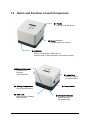
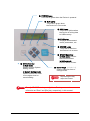
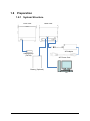
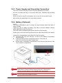
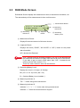
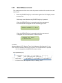
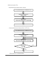
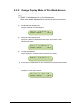
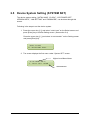
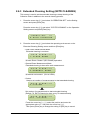
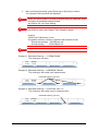
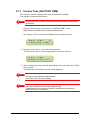
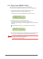
Rev. 2.4.1 Microbe Sensor BM-300C User’s Manual Index Dear Sharp Customer ............................................................................................. 3 Important Safety Precautions .................................................................................. 4 AC Adapter and Power Cord ················································································· 7 Optional Battery ···································································································· 8 Before Operating BM-300C..................................................................................... 9 1.1 1.2 1.3 1.4 1.5 General ······································································································· 10 Accessories ································································································ 10 Options (Sold separately) ··········································································· 10 Name and Function of each Component ····················································· 11 Important Handling Information ··································································· 13 1.5.1 Installation (Operating and Storage Environment) ..............................13 1.5.2 Devices compatible with USB port of this Device ................................13 1.6 Cleaning ······································································································ 13 1.7 Consumables ······························································································ 14 1.8 Preparation·································································································· 15 1.8.1 System Structure .............................................................................15 1.8.2 Installation........................................................................................16 1.8.3 Power Supply and Grounding Connection........................................17 1.8.4 Battery (Optional) .............................................................................17 How to Use .......................................................................................................... 18 2.1 Turn ON of the Device ················································································· 19 2.2 Turn OFF of the Device ··············································································· 19 2.3 RUN Mode Screen ······················································································ 20 2.3.1 Start Measurement .........................................................................21 2.3.2 Change Display Mode of Run Mode Screen ....................................23 2.3.3 PASSWORD Screen ......................................................................25 2.4 Select Screen ······························································································ 26 2.4.1 Screen Menu Tree ...........................................................................27 2.4.2 Save Parameter (SAVE SETTING) ..................................................29 2.4.3 Read Parameter (LOAD SETTING) .................................................30 2.4.4 Export/Import data to/from USB (USB STORAGE) ..........................31 2.5 Device System Setting (SYSTEM SET) ······················································· 36 2.5.1 Parameter Number to use at Startup (INITIAL NUM) .......................37 2.5.2 Clock Setting (CLOCK) ....................................................................38 2.5.3 LCD Power Off (LCD POWER OFF) ................................................39 2.5.4 Version Information (VERSION INFO) .............................................40 -1- 2.5.5 LAN Setting (LAN SETTING) ...........................................................41 2.5.6 Password Lock (PASSWORD) .........................................................43 2.5.7 Buzzer (BUZZER) ............................................................................46 2.6 Operation Setting (OPERATION SET) ························································ 47 2.6.1 Measurement Mode (MEASURE MODE) .........................................48 2.6.2 Data Output Mode (DATA OUT MODE) ...........................................49 2.7 Measurement Condition (MEASURE COND) ·············································· 52 2.7.1 Suction Time (SUCTION TIME) .......................................................53 2.7.2 Measurement Interval (MEASURE GAP) .........................................54 2.7.3 Repeat Cycle (REPEAT CYCLE) .....................................................55 2.7.4 Alarm Threshold (ALARM LEVEL) ...................................................56 2.8 Result Output Condition (RESULT COND) ·················································· 57 2.8.1 Measurement Times (MEASTIMES 2.8.2 Measurement Period (MEASPERIOD AVE)......................................58 AVE) ................................59 2.9 Maintenance Screen ··················································································· 60 2.9.1 Self Check (SELF CHECK) ..............................................................60 2.9.2 Measurement Counts Check (MEASURE COUNT) .........................62 Others.................................................................................................................. 63 3.1 3.2 3.3 3.4 Troubleshooting··························································································· 64 Error Code··································································································· 66 How to indentify failure ················································································ 67 Specifications ······························································································ 68 -2- Dear Sharp Customer Thank you for choosing Sharp Microbe Sensor. (Model Name: BM-300C, the “Product”). Please read this manual thoroughly before the use for your safety and proper use of the Product, especially Important Safety Precautions, and keep this manual near the device so that you can refer to it whenever required. Notice The Product is designed and manufactured for general applications in ordinary industries use. Therefore, it must not be used in specific applications that can affect the health or safety of the public. Such applications require a special warranty of quality that SHARP explicitly does NOT offer for our Product. Information in this manual is subject to change without notice and does not represent a commitment on the part of Sharp Manufacturing Systems Corporation (“SHARP”) and its sales distributors. SHARP and its sales distributors shall not be liable for technical or editorial errors or omissions contained herein; nor for incidental or consequential damages resulting from the furnishing, performance, or use of this material. SHARP strongly recommends you to store important data on a separate memory device. Data may be lost or altered in virtually any electronic memory product under certain circumstances like by electrostatic discharge and electromagnetic field. Therefore, SHARP assumes no responsibility for data lost or otherwise rendered unusable whether as a result of improper use, repairs, defects or any other causes. SHARP assumes no responsibility for direct, special, incidental or consequential damages resulting from the use of this Product including the pre-installed software and any of its functions, including but not limited to loss of revenue, loss of actual or anticipated profits, loss of business, loss of reputation, loss of damage to or corruption of data, financial losses or claims from third persons, except the liability waived in accordance with the applicable law. Please follow the terms and conditions for use of software if it is set out by the provider of the software. You are not allowed to copy or reprint a part or whole of this manual without written approval by SHARP. The Product including its accessory may be changed without notice for improvement. -3- Important Safety Precautions ● This instruction manual and the Product itself adopt symbols for precautions for safety. The results caused by incorrect use and non conformity to the symbols are classified as follows: Please fully understand each precaution for safety and observe them. Danger Indicates potentially very hazardous situation which, if not avoided, is likely to result in death or serious injury. Warning Indicates potentially hazardous situation which, if not avoided, is likely to result in death or serious injury. Caution Indicates potentially very hazardous situation which, if not avoided, is likely to result in minor or moderate injury or property damage. ● Meaning of each symbol Indicates Pay Attention (Danger, Warning and Caution) Indicates Do Not Indicates Must Do This Product is a Class 1 Laser Product. (IEC 60825-1:2007) A Class 1 laser is safe under all conditions of normal use. (Wavelength: 405nm, Maximum Power: 60mW) Be sure to operate the product according to the User’s Manual and Instruction Manual. Never operate the Product in the manner not described in the manuals. Failure to follow this may result in injury or damage to the Product. CLASS 1 LASER PRODUCT IEC 60825-1:2007 Danger To avoid electric shock hazard, fire, etc. ● Do not pour, put or insert metals such as a pin and wire, foreign materials and liquid into or on the vent holes, holes and terminals of the Product. ● Do not disassemble, repair or alter the Product by not qualified personnel. Failure to follow these may result in electric shock, injury or damage to the Product. -4- Warning To avoid electric shock hazard, fire, etc. ● The Product must be grounded. The end of the power cord of this Product has a 3 prong plug with grounding pin. Be sure to connect it to a 3 pin outlet with grounding connection. Failure to follow this may result in electric shock and fire. ● Be sure to use the exclusive battery charger for BM-300C. Failure to follow this may result in fire or damage to the Product. ● Be sure to plug the power cord of the Product into 100 to 240VAC, power outlet. Connecting to other voltage power outlet will result in fire and damage to the Product. ● Do not open the battery compartment while the Product is powered. Failure to follow this may result in electric shock. ● Be careful not to pinch your fingers when opening or closing the battery compartment. Failure to follow this may result in injury. ● Do not use or store the Product in outdoor or in a place where the environment temperature exceeds 60℃ or under direct sun light. Failure to follow this may result in fire or damage to the Product. ● Should the Product become hot, smoke, smell unusually, etc. turn off the power of the Product and unplug the power cord immediately and contact our dealer for repair. Failure to follow these may result in fire and electric shock. ● Do not damage, disassemble or alter the Product. Failure to follow this may result in fire and electric shock. -5- Caution To avoid electric shock hazard, fire, etc. ● Do not use the Product in dusty or humid place or where the Product is exposed to oil mist, steam, etc. Failure to follow this may result in fire and electric shock. ● Do not use the Product on not flat or unstable surface. Failure to follow this may result in injury. ● Do not plug or unplug the power plug with wet hands or put container with fluid filled around the Product. Failure to follow this may result in electric shock. ● Do not hit, drop or give mechanical vibration and shock to the Product. Failure to follow these may result in fire, electric shock or damage to the Product. ● Be sure to hold the handle of the Product when carryin it. Failure to follow this may result in injury. ● Turn off the Power Switch and disconnect the power cord from the power outlet when not using the Product for long time. ● Do not use the Product for the purpose or in the manner other than those specified in this manual. -6- AC Adapter and Power Cord Warning To avoid electric shock hazard, fire, etc. ● Be sure to plug the power cord into 100 to 240VAC, 15A, power outlet. ● Be sure to ground the power cord. Failure to follow these may result in fire and electric shock. ● Plug the power cord directly to the power outlet. Putting too many plugs in one outlet may result in fire. ● Do not plug or unplug the power plug with wet hands. Failure to follow this may result in electric shock. Warning To avoid electric shock hazard, fire, etc. ● Do not damage, disassemble or alter the AC adapter and power cord. Do not put heavy material on, pinch or bend forcedly the power cord. Failure to follow these may result in fire and electric shock. ● Do not use the AC adapter in outdoor or in a place where the environment temperature exceeds 60℃ or under direct sun light. Failure to follow this may result in fire or damage to the Product. Caution To avoid electric shock hazard, fire, etc. ● Plug or unplug the power cord by holding the plug body. ● Plug the power plug securely into the power outlet. Failure to follow these may result in fire and electric shock. ● Do not plug the power plug into loose power outlet. Failure to follow this may result in fire and electric shock. ● Clean the power plug with dry cloth if it is dusty or contaminated. Failure to follow this may result in fire and electric shock. ● Disconnect the power plug from the power outlet when not using the Product for long time. -7- Optional Battery Caution To avoid electric shock hazard, fire, etc. ● Do not open or dismantle battery. ● Do not expose the battery to heat or fire. Avoid storage in direct sunlight. ● Do not short circuit the battery. ● Do not store the batteries haphazardly in a box or drawer where they may short circuit each other or be short circuited by other metal objects. ● Do not remove the battery from its original packaging unit required for use. ● Do not subject the battery to mechanical shock. ● In the event of a battery leaking, do not allow the liquid to come in contact with skin or eyes. If contact has been made, wash the affected area with copious amounts of water and seek medical advice. ● Be sure to charge the battery only with its exclusive Battery Charger (RRC-SMB-UBC). Do not use any charger other than this. ● Observe the plus (+) and minus (-) marks on the battery and the device and ensure correct use. ● Keep the battery out of the reach of children. ● Keep the battery clean and dry. ● The battery needs to be charged before use. ● When possible, remove the battery from the device when not in use. ● Do not store the battery longer than 1 month in discharged state. ● Do not storage battery longer than 1 year without recharge. ● The battery must be recycled or disposed of properly. Recommendation: Store the battery at below 20℃, low humidity, no dust and no corrosive gas atmosphere. Store the battery with a state of charge between 50 – 80%. -8- Before Operating BM-300C -9- 1.1 General The Microbe sensor, BM-300C, is a device designed to detect microbial biomass that includes such as fungi, bacteria, noncutlturable living microbe and killed microbe in about 10 minutes and intended for indoor use. It employs Sharp’s proprietary technology that utilizes increase in self fluorescence of microbes under heating. 1.2 Accessories Please check that the following are included right after unpacking the Product 1.3 AC Adapter x 1 AC Power Cord x 1 User’s Manual (English) x 1 Options (Sold separately) Battery, Model Name: RRC2024 Battery Charger, Model Name: RRC-SMB-UBC - 10 - 1.4 Name and Function of each Component ① Handle Used to carry the device ② Rubber Feet x 4 Provides space for exhaust. ③ USB Port Port for connecting an USB memory. (Used to back up the parameters and measured data) ④ Ethernet Connector Connector for Ethernet communication ⑦ Intake Vent Sucks air sample for measurement ⑤ Battery Compartment ⑧ Power Switch Sores optional battery ⑥ Cam Lock Used to lock the Battery Compartment ⑨ DC Input Terminals Used to connect AC Adaptor plug - 11 - ⑩ POWER Lamp Turns ON in green when the Device is powered ⑪ RUN Lamp Turns ON in green when the Device is in Run mode ⑫ USB Lamp Turns ON in yellow when the Device is writing data to USB memory. ⑬LCD Display Displays measurement result, parameters, etc. ⑭ ERROR Lamp Turns ON in red when the Device is in an error. ⑮ START/Enter Key In RUN mode: Used to start measurement. In Setting mode: Used to select an item. ⑰ MENU/Esc Key In Run mode: Used to access System Setting screen. ⑯ Cursor Keys (↑/↓/←/→) Used to select an item or change mode. In System Setting mode: Used to access the menu of one higher level or cancel setting. CAUTION Depressing the key stops the buzzer. The ⑮ START/Enter key and ⑰ Menu/Esc key are sometimes referred to as “Enter” and [Esc] key, respectively, in this manual. - 12 - 1.5 Important Handling Information 1.5.1 Installation (Operating and Storage Environment) Please be sure to store, install and use the device at a location not exposed to the following: Direct sunlight and heat (like near a heating appliance) Near the devices that generate magnetic field or has been magnetized High humidity causing condensing Dusty environment Mechanical vibration and impact Unstable table top Not observing the above may result in discoloration, deformation or damage to the device. Please do not use the device under the following gas environment Causes explosion, fire, etc. and hazardous to human... Causes deterioration or corrosion of the device Contains mist, liquid droplets, oil droplets or too much powder particles. Not observing the above may result in an accident or damage to or failure of the device as well as inaccurate measurement. When using the device that has been used in a low cleanliness degree area in a high cleanliness area, the measurement may not be done correctly. In such a case, maintenance of the device is required. Please consult your dealer. 1.5.2 Devices compatible with USB port of this Device Only a FAT 32 Formatted USB memory can be connected. The port cannot be used for any other purposes, like serial communication, etc. 1.6 Cleaning Be sure to unplug the power cord before cleaning the device. External of the Device Wipe off with soft, lint free cloth that is once dampened with water and then squeezed tightly for drying. Intake Vent and Exhaust Vent Brush off dirt around the intake vent and exhaust vent with a soft brush. - 13 - 1.7 Consumables Sample Collection Plate and Battery (Optional) are the consumables of this Device. Collection Plate The Collection Plate should be replaced at around every 5,000 times of sample collection. Contact our dealer to replace these consumables. Battery (Optional) The fully charged battery voltage goes down to 75% of the initial after 300 charging cycles. - 14 - 1.8 Preparation 1.8.1 System Structure Front View Back View AC Adapter USB Memory (FAT32) AC Power Cord Battery (Optional) PC - 15 - 1.8.2 Installation ■ Install the Device on a level, rigid and stable surface. ■ Place the Device such that Intake Vent faces the area to be measured. ■ Do not block the Intake Vent and Exhaust Vent at the bottom of the Device. Exhaust 排気口 Vent Intake Vent ・External Dimensions (mm) - 16 - 1.8.3 Power Supply and Grounding Connection The Device comes with a 3 pin Power Plug with grounding connection. Be sure to connect the Plug to 3 pin power outlet (100 – 240VAC) with grounding terminal. If the 3 pin power outlet is not available, use a 3 pin to 2 pin conversion plug and connect the grounding wire to a grounding terminal. 1.8.4 Battery (Optional) NOTE: The battery (RRC2024) is set to a sleep (no output voltage) mode at the time of factory release. Please be sure to charge the battery only with its exclusive Battery Charger (RRC-SMB-UBC) before the first use. The sleep mode is released automatically upon the initial charging. Please refer to the instruction manuals come with each component for the details. Install a fully charged battery according to the following steps: ■ Push the Cam Lock, turn and pull it to take out the Battery Compartment from the device. ■ Install the battery into the compartment with its Front Side up. Note: Do not insert the battery upside down. ■ Slowly push in the Battery Compartment into the device and push the Cam Lock to lock the compartment. Cam Lock CAUTION CAUTION When the battery voltage goes down to 10% or less (BO), the measurement result is stored in internal memory and not in USB memory. Be sure to check battery is fully charged before storing data. When the battery voltage goes down to 30% or less (BO), a buzzer will sound. Please fully charge the battery. - 17 - How to Use - 18 - 2.1 Turn ON of the Device Press the Power Switch on the back of the Device. Start Up screen will be displayed on the LCD display, Self Check function is performed for about 1 minute, PASSWORD screen will be displayed (※1) and then Run Mode screen will be displayed. Press the [START/Enter] key on the bottom right of the LCD Display to start measurement. 2.02.0001 BioSMS system Turn ON Power Switch ※1 Performs Self Check of 01 to 14. self check 01 RAM data check Self Check (about 1 min) ※2 PASSWORD(※2) Displayed only when Password Lock function is enabled. PLEASE COND: RUN Mode Screen START B-* 2.2 Turn OFF of the Device CAUTION Turning off the Device with Power Switch while it is in RUN mode may make the next measurement inaccurate. Following is the steps to turn off the device while it is in RUN Mode: 1. Press [MENU/Esc] key on the bottom left of the LCD Display. 2. Check that the LCD Display indicates “Please wait… “. 3. Check that the RUN lamp is OFF. 4. Then, press the Power Switch to turn OFF the Device. VAL= 10000n/m3 COND:GOOD B-* Press [MENU/Esc] Key Program ending process (about 1 min) ① Cooling (when the [MENU/Esc] key was pressed during heating) ② Cleaning Process (OP SUSPENDED) RADIATING HEAT.. (OP SUSPENDED) CLEANING.. . VAL= COND: RUN Mode Screen - 19 - 0n/m3 B-* 2.3 RUN Mode Screen RUN Mode Screen displays the measurement result, measurement conditions, etc. The start and stop of the measurement is done on this screen. ① Measurement Result VAL=1.23456V/s COND:GOOD B5* ④ Measuring Indicator A ② Judgment Result ⑤ Measuring Indicator B ③ Remaining Battery Level ① Measurement Result: Displays fluorescent amount of airborne microbe. ② Judgment Result: Displays the result (“GOOD”, “NO GOOD” or “N.D.”) based on the preset alarm threshold. N.D. denotes Not Detected. CAUTION “N.D.” denotes that the microbial biomass is too low to be detected and the measured environment is highly clean and not an error of the device. If you want to get a numeric result rather than “N.D.”, increase the air sucking volume (See section 2.7.1). There is a case a numeric value can be obtained. ③ Remaining Battery Level: Displays the Level in 10 steps (10 %/step). B9: (100 %- 90 %) to B0: (9%- 0%) B –: (Optional Battery is not installed) ④ Measuring Indicator A: The “:” blinks during the measurement. ⑤ Measuring Indicator B: Indicates “*”→ “+”→ “×” in the order during measurement. Indicates “*” when the measurement is stopped. - 20 - 2.3.1 Start Measurement The measurement will be done under the preset conditions like suction time and repeat cycle. 1. Press the [START/Enter] key on the bottom right of the LCD Display to start measurement. RUN Lamp turns ON when the [START/Enter] key is pressed. When the [MENU/Esc] key is pressed during the measurement, the measurement is stopped and the RUN lamp goes OFF. VAL=1.23456V/s COND:GOOD B5* When the [MENU/Esc] key is pressed during the measurement is stopped, the screen will switch to Select screen. (BASE OP SEL) 1.MEASURE Example: Measure Mode: AUTO, Suction Time: 5 min, Measure Gap (interval): 15 min Note: Once the Measure Mode is set to AUTO, the measurement is repeated until it is stopped by the [MENU/Esc] key pressing. Press [START/Enter] key Preprocess 15 min Measure Gap → A B C A B C 5 min 5 min 5 min 5 min 5 min 5 min ① 15 min ③ 15 min A: Suction Time, B: Inspection Time, C: Waiting Time - 21 - ② 15 min (Reference) Operation Flow ・ Single Measurement: Measure Mode = Manual Press [START/Enter] key on RUN Mode screen Preprocess (cleaning, etc.) Approx. 15 min Measurement Measurement Gap(Suction + Inspection) End ・ Continuous Measurement: Measure Mode = AUTO-xxxx Press [START/Enter] key on RUN Mode screen Preprocess (cleaning, etc.) Approx. 15 min Measurement Measurement Gap(Suction + Inspection) [MENU/Esc] Key Pressed? Yes End ※ See section 2.6.1. for Measure Mode. - 22 - No 2.3.2 Change Display Mode of Run Mode Screen 1. The Display Mode of the RUN Mode screen can be changed with the cursor key [↑/↓]. ※ “COND:” will be displayed in any Run Mode screen. Please note that the displayed result is that of the last measurement. ① Microbial Biomass Display Mode Displays measured microbial biomass. VAL=1.23456V/s COND:GOOD B5* ② Differential Value Display Mode Displays the difference between the last and the one before the last measurement results. DIF=1.23456V/s COND:GOOD B5* ③ Average Display Mode Always displays the average of last 6 measurement results. AVE=1.23456V/s COND:GOOD B5* ※ The average is updated whenever the measurement has been made 6 times. ④ Date and Time Display Mode Displays the current date and time. 12/12 00:00:00 COND:GOOD B5* - 23 - ⑤ Information Display Mode Displays the information on the current measurement. PRO:NOM PAR:1 COM:WAI ERR:0 * ・PRO: Measurement Process PRE: Preprocess, NOM: Normal process, EXT: Extended process ・PAR: Parameter Number Indicates the parameter number of the measurement underway. ・COM: Communication Status: WAI: Waiting, EST: communication Established ・ERR: Error Code Displays an Error Code when an error occurs. See section 3.2 for Error Code. ⑥ Time Left Display Mode Displays the time left until current measurement result is output and the time to start next measurement. ResultDISP:1 NextStart :1 * ・ResultDISP: (minute) Displays the time until current measurement result is output. ・NextStart: (minute) Displays the time until next measurement starts. 2. The Display Mode of the RUN Mode screen can be changed with the cursor key [←/→]. ① Measurement Record Display Mode The last 9 measurement records can be recalled. VAL=1.23456V/s COND:GOOD P1* Change the Page number (P1 to P9) with the cursor key to access past records. - 24 - 2.3.3 PASSWORD Screen When the Password Lock function is enabled, PASSWORD screen will be displayed after the start up of the device. Enter the appropriate password. See section 2.5.6 for how to enable password lock function. Example: Following is the steps to log in as an administrator. 1. Enter a password. The cursor position can be changed with the [←/→] key. A number and alphabet can be selected with the [↑/↓] key. A password must be comprised of numbers and/or characters with min length 4 and max length 10. Press [Enter] key to finish password entry or [Esc] key to cancel the entry. PASSWORD: 0 2. After confirming that “log in: ADMIN” will be displayed on the screen, press the [Enter] key. log in: ADMIN Press Enter Key CAUTION CAUTION By performing the above steps, the password is asked whenever trying to switch from RUN mode screen to Select screen and the parameters for administrator cannot be changed without the password entry. By enabling the password lock function, it is possible to limit the access to the menus (or parameters) by administrator, user and guest. See section 2.5.6. for the detail. - 25 - 2.4 Select Screen You can select one of the 3 menus, “Measure”, “Maintenance” or “Setting”, from this screen. This screen can be accessed by pressing [MENU/Esc] key on RUN Mode screen. Press the cursor key [↑/↓] to select a menu and press [Enter] key to access the selected menu. 1.MEASURE Go to RUN Mode screen when [Enter] key is pressed. (BASE OP SEL) 1.MEASURE 2.MAINTENANCE Go to Maintenance screen when [Enter] key is pressed. (BASE OP SEL) 2.MAINTENANCE 3.SETTING Go to Setting screen when [Enter] key is pressed. (BASE OP SEL) 3.SETTING - 26 - 2.4.1 Screen Menu Tree 1. MEASURE (RUN Mode screen) VALUE Microbial Biomass DIFERENCE Differential Value AVERAGE Average ⇒ Section 2.3.2 TIME Date and Time INFORMATION Information MEASURE TIME Calibration Time Left for Measurement 2. MAINTENANCE (Maintenance screen) 1. CALIBRATION ⇒ For Servicing staff only Calibration 2. SELF CHECK ⇒ Section 2.9.1 Self Check 3. MEASURE COUNT ⇒ Section 2.9.2 Measurement Counts 3. SETTING (Setting screen) 1. SAVE SETTING ⇒ Section 2.4.2 Save parameter setting 2. LOAD SETTING ⇒ Section 2.4.3 Load parameter setting ① 3. USB STORAGE Write data to USB 4. INITIALIZE ⇒ Section 2.4.5 Initialization 5. SYSTEM SET Device System Setting 6. OPERATION SET Operation Setting ※ Access Authority: (When Password Lock function is enabled). : Administrator only : Administrator + User : Everybody - 27 - ② ③ ① 1. EXPORT(ALL) 2. EXPORT(PARAM) ⇒ Section 2.4.4 3. IMPORT(PARAM) 4. EXPORT(EIGEN) ② 1. INITIAL NUM ⇒ Section 2.5.1 Parameter number to use at start up 2. CLOCK ⇒ Section 2.5.2 Clock setting 3. LCD POWER OFF ⇒ Section 2.5.3 LCD power off setting 4. VERSION INFO ⇒ Section 2.5.4 Version information 5. LAN SETTING ⇒ Section 2.5.5 LAN setting 6. PASSWORD ⇒ Section 2.5.6 Password lock setting 7. BUZZER ⇒ Section 2.5.7 Buzzer setting ③ 1. MEASURE MODE ⇒ Section 2.6.1 Measurement Mode 2. DATA OUT MODE ⇒ Section 2.6.2 Data output Mode 3. MEASURE COND 1. SUCTION TIME Measurement Condition Mode Suction Time 2. MEASURE GAP ⇒ Section 2.7.1 ⇒ Section 2.7.2 Measurement Interval 3. REPEAT CYCLE ⇒ Section 2.7.3 Repeat Cycle 4. ALARM LEVEL ⇒ Section 2.7.4 Threshold for Alarm 1. RESULT CYCLE ⇒ Section 2.8.1 Measurement times to make average 4. RESULT COND Result Output Condition 5. EXTD CLEANING 2. RESULT PERIOD Measurement period to make average ⇒ Section 2.6.3. Extended Cleaning Setting 6. VARIABLE ⇒ For Servicing staff only Variable Setting 7. DETAIL SET ⇒ Section 2.8.2 ⇒ For Servicing staff only Detail Setting - 28 - 2.4.2 Save Parameter (SAVE SETTING) What is a parameter? To make a measurement, sample sucking time, measurement/output mode, etc. must be set. The group of setting is called as a Parameter with this device and saved under a parameter number. Maximum 100 kinds of parameters can be saved in the internal flash memory of the device. CAUTION Use a Parameter number within 1 and 90. Parameter numbers 91 to 100 are reserved for servicing purpose. Following is the steps to store a parameter to the internal flash memory. The saved parameter can be utilized by reading it from the memory. (See section 2.4.3) 1. Press the cursor key [↑/↓] and select “3.SETTING” on the Select screen and press [Enter] key to access Setting screen. (See section 2.4) Press the cursor key [↑/↓] and select “1.SAVE SETTING” on the Setting screen and press [Enter] key. (SETTING) 1.SAVE SETTING 2. Select a parameter number to save with the cursor key [↑/↓] key. ※ Example: Use “01” as the parameter number. (SAVE SETTING) NUMBER SEL: 01 3. Press [Enter] key. CAUTION 4. CAUTION “please wait. . .” will be displayed during the saving. (SAVE SETTING) please wait.. . The Setting screen will be displayed if the saving has been completed successfully. Please note that data in the selected parameter number is overwritten once “Save Setting” is performed. - 29 - 2.4.3 Read Parameter (LOAD SETTING) The stored parameter can be read from the built in flash memory. Following is the steps to read a parameter from the built in flash memory. 1. Press the cursor key [↑/↓] and select “3.SETTING” on the Select screen and press [Enter] key to access Setting screen. (See section 2.4) Press the cursor key [↑/↓] and select “2.LOAD SETTING” on the Setting screen and press [Enter] key. (SETTING) 2.LOAD SETTING 2. Select a parameter number to read with the cursor key [↑/↓] key. ※ Example: Use “01” as the parameter number. (LOAD SETTING) NUMBER SEL: 01 3. Press [Enter] key. “please wait. . .” will be displayed during the reading. (LOAD SETTING) please wait.. . 4. CAUTION The Setting screen will be displayed if the saving has been completed successfully. Parameter under editing is deleted once the “Load Setting” is performed. Please be sure to perform “Save Parameter” to save the parameter under editing before performing “Load Setting”, as necessary. See section 2.4.2. - 30 - 2.4.4 Export/Import data to/from USB (USB STORAGE) It is possible to export stored measurement data, parameters and information management file to an USB memory and import parameters from an USB memory. CAUTION CAUTION CAUTION The USB memory must be FAT32 format without a protection function. Each item is stored in the device under the file name as follows: Measurement data (res***.csv) Parameters (param***.csv) Information management file (info***.csv) They are kept in the device even after exporting to USB. When operating the device on Battery, be sure to fully charge the battery before writing data to USB memory. Data is not written to USB when battery level goes down to “B0”. 1. Connect an USB memory (FAT32 format) to the USB port of this device. 2. Press the cursor key [↑/↓] and select “3.USB STORAGE” on the (SETTING) screen and press [Enter] key. (See section 2.4) (SETTING) 3.USB STORAGE 3. Press the cursor key [↑/↓] and select the desired item and press [Enter] key. ・ Export all the stored data to an USB memory.(EXPORT{ALL} ) (USB STORAGE) 1.EXPORT{ALL} Export: please wait.. . Exporting data to an USB memory. During the exporting, USB lamp turns on and the message [please wait …] will be displayed. - 31 - Export:param000 Press enter key. When the exporting is finished, USB lamp turns off and the message [Press enter key.] will be displayed. When the [Enter] key is pressed, (SETTING) screen as shown above step 2 will be displayed. ※ The “param000” on the right of “Export” is the file name exported. The number “000” is automatically incremented according to the file name already exists. Example: If “param000” exits, the data is stored under the file name of “param001”. ・ Export parameters to an USB memory. (EXPORT{PARAM} ) (USB STORAGE) 2.EXPORT{PARAM} Export: please wait.. . Exporting data to an USB memory. During the exporting, USB lamp turns on and the message [please wait …] will be displayed. Export:param000 Press enter key. When the exporting is finished, USB lamp turns off and the message [Press enter key.] will be displayed. When the [Enter] key is pressed, (SETTING) screen as shown above step 2 will be displayed. ※ The “param000” on the right of “Export” is the file name exported. The number “000” is automatically incremented according to the file name already exists. Example: If “param000” exits, the data is stored under the file name of “param001”. - 32 - ・ Import parameters from an USB memory.(IMPORT{PARAM} ) (USB STORAGE) 3.IMPORT{PARAM} (Import{PARAM} ) select:param000 Select the file name to import according to the following steps: Press the [←] o r [→] key and select the digit to change and select the number with the cursor key [↑/↓]. Repeat this until desired number is entered. Press the [Enter] key. Import is started. Import:param000 please wait.. . Importing data from an USB memory. During the importing, USB lamp turns on and the message [please wait …] will be displayed. Import:param000 Press enter key. When the importing is finished, USB lamp turns off and the message [Press enter key.] will be displayed. When the [Enter] key is pressed, (SETTING) screen as shown above step 2 will be displayed. 4. Remove the USB memory from the USB port of the device. - 33 - (Reference) Example of exporting a file to an USB memory ・Measurement data file: res000.csv (res file output example) ① ② ③ ④ Output Data ① DataTime: ② Result: ③ ParameterNumber: ④ MeasureMode: ⑤ DataOutputMode: ⑥ ⑦ ⑧ ⑨ ⑩ PeriodMeasureCount: BioCount Value: Differential Value: Average Value: collection time(sec): ⑤ ⑥ ⑦ ⑨ Measurement finished time Result (GOOD,NO GOOD, NOT DETECTED) Measurement parameter number (1 -100) Measurement Mode 0: Manual, 1: Auto-Average, 2: Auto-Period, 3: Auto-Every Data output mode 0: V/sec, 1: n/m3 (fungi), 2: n/m3 (bacteria) Number of measurements for judgment Microbial biomass Difference value (Previous – Current) Average value (Average of last 6 measurements) Suction time (300 - 7200) ・Information management file: info000.csv (inf file output example) ① ② ③ ④ ⑤ Output Data ① MAC Address: ② IP Address: ③ subnet mask: ④ default gateway: ⑤ version info: ⑧ MAC address IP address Subnet mask Default gateway Version information - 34 - ⑩ 2.4.5 Initialization (INITIALIZE) All the parameters and measurement data in the internal flash memory can be initialized. Following is the steps to initialize the internal flash memory. CAUTION All the parameters and/or measurement data in the internal flash memory are lost once the initialization is performed. 1. Press the cursor key [↑/↓] and select “3.SETTING” on the Select screen and press [Enter] key to access Setting screen. (See section 2.4) Press the cursor key [↑/↓] and select “4.INITIALIZE” on the Setting screen and press [Enter] key. (SETTING) 4.INITIALIZE 2. Press the cursor key [↑/↓] and select the area to initialize, “1. ALL” or “2. Result Data” and press [Enter] key. ・ALL: Initialize all the parameters and measurement data. (INITIALIZE) 1.ALL ・RESULT DATA: Initialize only the measurement data (INITIALIZE) 2.RESULT DATA 3. Confirmation screen for initialization will be displayed. Press [Right (→)] key to initialize or [Esc] key to cancel the initialization. INITIALIZE? 1 YES:Right NO:Esc 4. “please wait...” will be displayed during the initialization. (INITIALIZE) please wait.. . 5. The device automatically restarts after finishing the initialization. - 35 - 2.5 Device System Setting (SYSTEM SET) The device system setting, “INITIAL NUM”, “CLOCK”, “LCD POWER OFF”, VERSION INFO”, “LAN SETTING” and “PASSWORD”, can be done through this screen. Following is the steps to set the device system. 1. Press the cursor key [↑/↓] and select “3.SETTING” on the Select screen and press [Enter] key to access Setting screen. (See section 2.4) Press the cursor key [↑/↓] and select “5.SYETEM SET” on the Setting screen and press [Enter] key. (SETTING) 5.SYETEM SET 2. The screen displays the first menu under “System SET” screen. Higher Level Menu Name (SYSTEM SET) 1.INITIAL NUM Selected Item - 36 - 2.5.1 Parameter Number to use at Startup (INITIAL NUM) Following is the steps to set the parameter number to use at start up. 1. Press the cursor key [↑/↓] and select “5.SYETEM SET” on the Setting screen and press [Enter] key. Press the cursor key [↑/↓] and select “1.INITIAL NUM” on the System Set screen and press [Enter] key. (SYSTEM SET) 1.INITIAL NUM 2. Press the cursor key [↑/↓] and select the “parameter number to use (01 to 100) at start up” on the INITIAL NUM screen and press [Enter] key. ※ Example: Use “01” as the parameter number. (INITIAL NUM) NUMBER SEL: 01 3. The System Set screen will be displayed. - 37 - 2.5.2 Clock Setting (CLOCK) Following is the steps to set the clock. 1. Press the cursor key [↑/↓] and select “5.SYETEM SET” on the Setting screen and press [Enter] key. Press the cursor key [↑/↓] and select “2.CLOCK” on the System Set screen and press [Enter] key. (SYSTEM 2.CLOCK 2. Press the cursor key [←/→] and select Year (last 2 digits), Month, Date, Hour or Minute position and enter the appropriate value with the cursor key [↑/↓]. ※ The cursor position is indicated by blinking “##”. ※ Depressing the cursor keys [↑/↓] changes the value in 10 steps. (CLOCK) 13/10/01 3. SET) 08:30 After confirming the data entered, press [Enter] key to set the clock or [Esc] key to cancel. The System Set screen will be displayed. - 38 - 2.5.3 LCD Power Off (LCD POWER OFF) Following is the steps to set the time to turn off back light of LCD display automatically for saving battery power. 1. Press the cursor key [↑/↓] and select “5.SYETEM SET” on the Setting screen and press [Enter] key. Press the cursor key [↑/↓] and select “3.LCD POWER OFF” on the System Set screen and press [Enter] key. (SYSTEM SET) 3.LCD POWER OFF 2. Press the cursor key [↑/↓] and set the time to turn off back light of LCD display within 00 and 60 minutes. ※ When 00 is set, the back light turns on continuously. (LCD POWER OFF) 10min(00:NO OP) 3. After confirming the entered data, press [Enter] key to set the time or [Esc] key to cancel. The System Set screen will be displayed. - 39 - 2.5.4 Version Information (VERSION INFO) Following is the steps to check the version information of this device. 1. Press the cursor key [↑/↓] and select “5.SYETEM SET” on the Setting screen and press [Enter] key. Press the cursor key [↑/↓] and select “4.VERSION INFO” on the System Set screen and press [Enter] key. (SYSTEM SET) 4.VERSION INFO 2. After confirming the displayed version information, press [Enter] key. The System Set screen will be displayed. (VERSION INFO) 1.00.0000 - 40 - 2.5.5 LAN Setting (LAN SETTING) Following is the steps to do LAN related setting of this device. ※ Check with your network administrator for the setting details. 1. Press the cursor key [↑/↓] and select “5.SYETEM SET” on the Setting screen and press [Enter] key. Press the cursor key [↑/↓] and select “5.LAN SETTING” on the System Set screen and press [Enter] key. (SYSTEM SET) 5.LAN SETTING 2. Press the cursor key [↑/↓] and select the item for TCP/IP setting and press [Enter] key. ・1. IP Address (IP ADRESS) (LAN 1.IP SETTING) ADDRESS (IP ADDRESS) 192.168.001.010 Press the cursor key [←/→] and select the position to input the IP address and enter the number with the cursor key [↑/↓]. After confirming the displayed IP address, press [Enter] key to set the address or [Esc] key to cancel the entry. ・2. Subnet Mask (SUBNET MASK) (LAN SETTING) 2.SUBNET MASK (SUBNET MASK) 255.255.255.000 Press the cursor key [←/→] and select the position to input subnet mask and enter the number with the cursor key [↑/↓]. After confirming the displayed Subnet Mask, press [Enter] key to set the address or [Esc] key to cancel the entry. - 41 - ・3. Default Gateway (GATEWAY) (LAN SETTING) 3.GATEWAY (GATEWAY) 000.000.000.000 Press the cursor key [←/→] and select the position to input gateway and enter the number with the cursor key [↑/↓]. After confirming the displayed gateway, press [Enter] key to set the address or [Esc] key to cancel the entry. 3. After TCP/IP related setting is finished and [Enter] key is pressed, a screen to prompt rebooting (once turn off and then turn on) of the device will be displayed. Press [Enter] key. PLEASE REBOOT Press Enter Key 4. Once turn off the Power Switch of the device and then turn it on to reboot and update the TCP/IP setting of the device. CAUTION TCP/IP related setting becomes effective only after the device is rebooted. - 42 - 2.5.6 Password Lock (PASSWORD) By enabling this password lock function, it is possible to limit the access to the menus (or parameters) of this device by administrator, user and guest. This function is helpful in preventing unintended change of the parameters by not authorized personnel. Please see section 2.4.1 Screen Menu Tree for the accessible menu. 1. Press the cursor key [↑/↓] and select “5.SYETEM SET” on the Setting screen and press [Enter] key. Press the cursor key [↑/↓] and select “6.PASSWORD” on the System Set screen and press [Enter] key. (SYSTEM SET) 6.PASSWORD 2. Press the cursor key [↑/↓] and select the item to set and press [Enter] key. ・Password setting for Administrator (ADMINISTRATOR) (PASSWORD) 1.ADMINISTRATOR ・ Enter old password. (Default: 0000) (ADMIN)OLD: 0000 Use [←/→] key to select cursor position and enter the old password with [↑/↓] key. After confirming the displayed password, press [Enter] key or [Esc] key to cancel. ※ Once [Esc] key is pressed, password needs to be entered from the first character. ・ Enter a new password comprised of numbers and/or characters with min length 4 and max length 10. (ADMIN)NEW: 0000 After confirming the displayed password, press [Enter] key or [Esc] key to cancel. - 43 - ・Check again that displayed password is what you have entered. (ADMIN)AGAIN: 0000 Press [Enter] key to register the password or [Esc] key to cancel. ・Password setting for USER (USER) (PASSWORD) 2.USER ・Enter old password. (Default: 0000) (USER)OLD: 0000 Referring to the steps under “Password setting for Administrator”, register a password for a User. ・Password setting for Guest (GUEST) (PASSWORD) 3.GUEST ・Enter old password.(Default: 0000) (GUEST)OLD: 0000000000 Referring to the steps under “Password setting for Administrator”, register a password for a Guest. ・Password Lock Function (ON/OFF) (PASSWORD) 4.ON/OFF Select ON or OFF of the password lock function with the [↑/↓] key. (ON/OFF) ON Press [Enter] key to register the change for password lock function or [Esc] key to cancel. - 44 - CAUTION CAUTION 3. Once this function is set to ON, password is asked to go into Setting Screen. Never change the password for “SPECIAL” that is for Servicing staff use. After password setting is finished and [Enter] key is pressed, a screen to prompt rebooting (once turn off and then turn on) of the device will be displayed. Press [Enter] key. PLEASE REBOOT Press Enter Key 4. Once turn off the Power Switch of the device and then turn it on to reboot and update the Password Lock function of the device. CAUTION Password related setting becomes effective only after the device is rebooted. - 45 - 2.5.7 Buzzer (BUZZER) The built in Buzzer can be enabled or disabled. 1. Press the cursor key [↑/↓] and select “5.SYETEM SET” on the Setting screen and press [Enter] key. Press the cursor key [↑/↓] and select “7.BUZZER” on the System Set screen and press [Enter] key. (SYSTEM SET) 7.BUZZER 2. Press the cursor key [↑/↓] and select either ON or OFF. When the Buzzer is enabled (set to ON), it sounds when the measurement result exceeded the threshold (See section 2.7.4.) or in an error CAUTION The buzzer never sounds when “BUZZER” is set to OFF. (ON/OFF) ON 3. After confirming the buzzer setting, press [Enter] key or [Esc] key to cancel. The System Set screen will be displayed. - 46 - 2.6 Operation Setting (OPERATION SET) This screen is used to set the condition of a parameter. Maximum 100 kinds of parameters can be stored in the device. 1. Press the cursor key [↑/↓] and select “3.SETTING” on the Select screen and press [Enter] key. Press the cursor key [↑/↓] and select “6.OPERATION SET” on the Setting screen and press [Enter] key. (SETTING) 6.OPERATION 2. Press the cursor key [↑/↓] and select the parameter number to edit and press [Enter] key. ※ Example: Use “01” as the parameter number. (OPERATION) NUMBER SEL: 3. SET 01 The first menu of Operation Setting screen will be displayed. Higher Level Menu Name (OPERATION) 01 1.MEASURE MODE Parameter Number Selected Item CAUTION When the device power is turned off before storing a parameter under changing, the parameter keeps old data. See section 2.4.2 for Save Setting. - 47 - 2.6.1 Measurement Mode (MEASURE MODE) This screen is used to select a mode for microbial biomass measurement: “1: MANUAL”, “2. AUTO-AVERAGE”, “3. AUTO-PERIOD” or “4. AUTO-EVERY”. 1. Press the cursor key [↑/↓] and select “6.OPERATION SET” on the Setting screen and press [Enter] key. Press the cursor key [↑/↓] and select “1.MEASURE MODE” on the Operation Setting screen and press [Enter] key. (OPERATION) 01 1.MEASURE MODE 2. Press the cursor key [↑/↓] and select a measurement mode and [Enter] key. ・1. Manual (Single measurement). (MEAS MODE) 1.MANUAL 01 ・2. AUTO-AVERAGE (Continuous measurement) Judge based on Average of set measurement times. (See section 2.8.1) (MEAS MODE) 01 2.AUTO-AVERAGE ・3. AUTO-PERIOD (Continuous measurement) Judge based on Average of set measurement period. (See section 2.8.2) (MEAS MODE) 01 3.AUTO-PERIOD ・4. AUTO-EVERY (Continuous measurement) Judge upon each measurement. (MEAS MODE) 4.AUTO-EVERY 1. CAUTION 01 After confirming the selected measurement mode, press [Enter] key or [Esc] key to cancel. The Operation Set screen will be displayed. When the device power is turned off before storing a parameter under changing, the parameter keeps old data. See section 2.4.2 for Save Setting. - 48 - 2.6.2 Data Output Mode (DATA OUT MODE) This screen is used to select the data output format: V/s: Fluorescent intensity or n/M3: fungi or bacteria equivalent. 1. Press the cursor key [↑/↓] and select “6.OPERATION SET” on the Setting screen and press [Enter] key. Press the cursor key [↑/↓] and select “2.DATA OUT MODE” on the Operation Setting screen and press [Enter] key. (OPERATION) 01 2.DATA OUT MODE 2. Press the cursor key [↑/↓] and select the desired output mode on the DOUT MODE Setting screen and then press [Enter] key. ・ Fluorescent intensity (V/s) The output of internal light receiving element will be displayed. (DOUT 1.V/s MODE) 01 ・ Fungi equivalent (n/M3) Outputs number of microbes assuming that all is fungi. (DOUT MODE) 01 2.n/M3(fungi) ・Bacteria equivalent (n/M3) Outputs number of microbes assuming that all is bacteria. (DISP MODE) 01 3.n/M3(bacteria) 3. After confirming the selected data output mode, press [Enter] key or [Esc] key to cancel. The Operation Set screen will be displayed. CAUTION When the device power is turned off before storing a parameter under changing, the parameter keeps old data. See section 2.4.2 for Save Setting. - 49 - 2.6.3 Extended Cleaning Setting (EXTD CLEANING) This screen is used to set the extended cleaning or deep cleaning of the Collection Plate in addition to the normal cleaning process. 1. Press the cursor key [↑/↓] and select “6.OPERATION SET” on the Setting screen and press [Enter] key. Press the cursor key [↑/↓] and select “5.EXTD CLEANING” on the Operation Setting screen and press [Enter] key. (OPERATION) 01 5.EXTD CLEANING 2. Press the cursor key [↑/↓] and select the operating environment on the Extended Cleaning Setting screen and then [Enter] key. ・Clean Room Measurement Mode Extended cleaning is not done. (EXTD CLEANI)01 1.CLEAN ROOM ※ Clean Room: Grade C (ISO Class8) equivalent. ・General Room Measurement Mode Extended cleaning is done after each measurement. (EXTD CLEANI)01 2.GENERAL ROOM ※ General environment (like an office) ・Custom Used to set number of measurements to start extended cleaning. (EXTD CLEANI)01 3.CUSTOM Set number of measurements to start extended cleaning. (Default: 70, EXTD Cleaning is done every 70 measurements) (EXTD CLEANI)01 070 (max200) Press the cursor key [←/→], select the position and enter the appropriate value (0 – 200) with the cursor key [↑/↓]. Then press [Enter] key to change the setting or [Esc] key to cancel. - 50 - 3. After confirming the setting, press [Enter] key or [Esc] key to cancel. The Operation Set screen will be displayed. CAUTION CAUTION CAUTION CAUTION When the device power is turned off before storing a parameter under changing, the parameter keeps old data. See section 2.4.2 for Save Setting. It is suggested to set the operating environment to “Clean Room” when the device is used under Grade C (ISO Class8) or higher Grade C: 1000CFU/m3 (Microbes) or less Acceptable maximum number of particles with diameter 0.5μm: During Non-working: 352,000 pcs./m3 During working: 3,520,000pcs./m3 The time for Extended Cleaning is fixed and 10 minutes. Example 1: Extended Cleaning = “1.CLEAN ROOM” The cleaning is not done. Suck 15 min Measure 5 min Measurement 1 Measurement 2 Measurement 3 Measurement 4 Example 2: Extended Cleaning = “2.GENERAL ROOM” The cleaning is done after each measurement Extended Cleaning (10 min) Suck 15 min Measure 5 min Measurement 1 Wait Measurement 2 Wait Measurement 3 Wait Example 3: Extended Cleaning = “3.CUSTOM” and “x 3” The cleaning is done after every 3 measurements. Extended Cleaning (10 min) Suck 15 min Measure 5 min Measurement 1 Measurement 2 Measurement 3 - 51 - Wait Measurement 4 2.7 Measurement Condition (MEASURE COND) This screen is used to set the Measurement Condition of each parameter number: “Suction time”, “Measurement Gap (Interval)”, “Repeat Cycle” and “Alarm Level”. 1. Press the cursor key [↑/↓] and select “3.SETTING” on the Select screen and press [Enter] key. Press the cursor key [↑/↓] and select “6.OPERATION SET” on the Operation Setting screen and press [Enter] key. (SETTING) 6.OPERATION 2. SET Press the cursor key [↑/↓] and select the parameter number to edit and press [Enter] key. ※ Example: Use “01” as the parameter number. (OPERATION) NUMBER SEL: 3. 01 Press the cursor key [↑/↓] until “3.MEASURE COND” will be displayed and press [Enter] key. (OPERATION) 01 3.MEASURE COND 4. The first menu of “MEAS COND” will be displayed. (MEAS COND) 01 1.SUCTION TIME - 52 - 2.7.1 Suction Time (SUCTION TIME) This screen is used to set the suction time of the airborne sample. The sample is sucked at 20L/minute. CAUTION Suction time of 5 minuts is recommened considering the contamination of the plate. 1. Press the cursor key [↑/↓] and select “1.SUCTION TIME” on the Measurement Condition screen and press [Enter] key. See section 2.7 for how to access Measurement Condition screen. (MEAS COND) 01 1.SUCTION TIME 2. Press the cursor key [↑/↓] and set the suction time. The time can be set in 1 minute step within 5 minutes to 2 hours. (SUCT TIME) 0h05min(max 2h) 3. After confirming the time entered, press [Enter] key to set the time or [Esc] key to cancel. The Measurement Condition screen will be displayed. CAUTION CAUTION When the device power is turned off before storing a parameter under changing, the parameter keeps old data. See section 2.4.2 for Save Setting. Stable measurements can be expected by setting the suction time longer when the cleanliness level of the sample is high. Contamination to the sample Collection Plate can be minimized by setting the suction time shorter. - 53 - 2.7.2 Measurement Interval (MEASURE GAP) This screen is used to set the measurement interval. The measurement is done at the set interval. 1. Press the cursor key [↑/↓] and select “2.MEASURE GAP” on the Measurement Condition screen and press [Enter] key. See section 2.7 for how to access Measurement Condition screen. (MEAS COND) 01 2.MEASURE GAP 2. Press the cursor key [←/→] and select the cursor position and enter the appropriate value with the cursor key [↑/↓]. The interval can be set in 1 minute step within 10 minutes to 24 hours. ※ The cursor position is indicated by blinking “##”. ※ Depressing the cursor keys [↑/↓] changes the value in 10 steps. (MEAS GAP) 01 00h10min(max24h 3. After confirming the time entered, press [Enter] key to set the time or [Esc] key to cancel. The Measurement Condition screen will be displayed. CAUTION CAUTION When the device power is turned off before storing a parameter under changing, the parameter keeps old data. See section 2.4.2 for Save Setting. The measurement GAP (interval) must be set such that it is longer than the “Suction Time” (Section 2.7.1) + 5 minutes (Inspection Time). Example: Set the MEAS GAP to 10 min or more when the Suction Time is 5 min. Example: Suction Time: 15 min, Inspection Time: 5 min (fixed), Measurement Interval: 20 min Output result A B 15 min 5 min Measurement Interval 20 min Output result A B 15 min 5 min Measurement Interval 20 min A: Suction Time, B: Inspection Time - 54 - Output result A B 15 min 5 min Measurement Interval 20 min 2.7.3 Repeat Cycle (REPEAT CYCLE) This screen is used to set the repeat cycle of the measurement. The measurement is stopped after it has been done for the set repeat cycle. Press the cursor key [↑/↓] and select “3.REPEAT CYCLE” on the Measurement Condition screen and press [Enter] key. 1. See section 2.7 for how to access Measurement Condition screen. (MEAS COND) 01 3.REPEAT CYCLE 2. Press the cursor key [↑/↓] and set the repeat cycle. The repeat cycle can be set to “NO-LIMIT” or within 01 to 99. NO-LIMIT means continuous and will be displayed when 0 is set with the cursor key. ※ Depressing the cursor keys [↑/↓] changes the value in 10 steps. (REPEAT 03 CYC) 01 (max99) 3. After confirming the cycle entered, press [Enter] key to set the cycle or [Esc] key to cancel. The Measurement Condition screen will be displayed. CAUTION When the device power is turned off before storing a parameter under changing, the parameter keeps old data. See section 2.4.2 for Save Setting. - 55 - 2.7.4 Alarm Threshold (ALARM LEVEL) This screen is used to set the alarm level or alarm threshold for OK/NG judgment. The device activates the built in buzzer when the measurement result exceeded the alarm threshold. Note: The device continues next measurement even if the measurement result exceeded the threshold without stopping automatically. The buzzer stops automatically when the measurement result goes below the threshold in the succeeding measurements. ※ Depress the (←) key to stop buzzer. 1. Press the cursor key [↑/↓] and select “4.ALARM LEVEL” on the Measurement Condition screen and press [Enter] key. See section 2.7 for how to access Measurement Condition screen. (MEAS COND) 01 4.ALARM LEVEL 2. Press the cursor key [↑/↓] and set the alarm level. ※ Depressing the cursor keys [↑/↓] changes the value in 10 steps. ・When the Data Output Mode = “V/s”: Set to “NO-LIMIT” or within 1 to 100. (ALARM LEVEL)01 50(V/s) ※ NO-LIMIT will be displayed when 0 is set with the cursor key. ・When the Data Output Mode = “n/m3”: Set to “NO-LIMIT” or within 1 to 100 (x 10,000). (ALARM LEVEL)01 50×10,000(n/m3) CAUTION Judgment result is always “GOOD” when “NO-LIMIT” is set. 3. After confirming the cycle entered, press [Enter] key to set the cycle or [Esc] key to cancel. The Measurement Condition screen will be displayed. CAUTION When the device power is turned off before storing a parameter under changing, the parameter keeps old data. See section 2.4.2 for Save Setting. - 56 - 2.8 Result Output Condition (RESULT COND) This screen is used to set the Result Output Condition when “AUTO-AVERAGE” or “AUTO-PERIOD” is set for the Measurement Mode (See section 2.6.1) 1. Press the cursor key [↑/↓] and select “6.OPERATION SET” on the Setting screen and press [Enter] key. (SETTING) 6.OPERATION SET 2. Press the cursor key [↑/↓] and select the parameter number to edit and press [Enter] key. ※ Example: Use “01” as the parameter number. (OPERATION) NUMBER SEL: 01 3. Press the cursor key [↑/↓] and select “4.RESULT COND” and press [Enter] key. (OPERATION) 01 4.RESULT COND 4. The first menu of “RESULT COND” screen will be displayed. (RESULT COND)01 1.RESULT CYCLE - 57 - 2.8.1 Measurement Times (MEASTIMES AVE) This screen is used to set the Result Output Condition when “AUTO-AVERAGE” is set for the Measurement Mode (See section 2.6.1) 1. Press the cursor key [↑/↓] and select “1.RESULT CYCLE” on the Result Condition screen and press [Enter] key. See section 2.8 for how to access Result Condition screen. (RESULT COND)01 1.RESULT CYCLE 2. Press the cursor key [←/→] and select the cursor position and enter the measurement times to make the average with the cursor key [↑/↓]. The times can be set within 0 to 99. (RESULT 03 CYC) 01 (max99) 3. After confirming the measurement times entered, press [Enter] key to set the time or [Esc] key to cancel. The Result Output Condition screen will be displayed. CAUTION When the device power is turned off before storing a parameter under changing, the parameter keeps old data. See section 2.4.2 for Save Setting. Example: Measurement Gap (Interval): 15 minutes, RESULT CYCLE (Measurement Times): 3 Output result: Average of 3 measurements A 5 ① B C 5 5 Interval 15 A B C 5 5 5 ③ Interval 15 A B C 5 5 5 ② Interval 15 Average of 3 measurements (①-③) A: Suction Time, B: Inspection Time, C: Wait Time (Unit: minute) - 58 - A B C 5 5 5 ① Interval 15 (④-⑥) 2.8.2 Measurement Period (MEASPERIOD AVE) This screen is used to set the Result Output Condition when “AUTO-PERIOD” is set for the Measurement Mode (See section 2.6.1) 1. Press the cursor key [↑/↓] and select “2.RESULT PERIOD” on the Result Condition screen and press [Enter] key. See section 2.8 for how to access Result Condition screen. (RESULT COND)01 2.RESULT PERIOD 2. Press the cursor key [←/→] and select the cursor position and enter the measurement period to make the average with the cursor key [↑/↓]. The period can be set within 0 minute to 2 hours ※ . Depressing the cursor keys [↑/↓] changes the value in 10 steps. (RESULT PERI)01 00h30min(max24h 3. After confirming the measurement period entered, press [Enter] key to set the period or [Esc] key to cancel. The Result Output Condition screen will be displayed. CAUTION CAUTION When the device power is turned off before storing a parameter under changing, the parameter keeps old data. See section 2.4.2 for Save Setting. The Measurement Period must be set such that it is longer than the “Suction Time” (Section 2.7.1) + 5 minutes (Inspection Time). Example: Set the MEAS GAP to 10 min or more when the Suction Time is 5 min. Example 1: Measurement GAP (Interval): 25 min, Result (measurement) Period: 50 min Output result: Average of each 50 min period B C A 5 5 15 ④ Interval 25 ④ Interval 25 ③ Average of 50 min period Interval 25 ② Interval 25 Average of 50 min period Example 2: Measurement GAP (interval): 25 min, Result (measurement) Period: 60 min Output result: Average of each 60 min period Average of 60 min period Average of 60 min period A: Suction Time, B: Inspection Time, C: Wait Time (Unit: minute) - 59 - 2.9 Maintenance Screen This screen is used to do self check, measurement count check and calibration of the device. Press the cursor key [↑/↓] and select “2.MAINTENANCE” on the Select screen. 1. 2.9.1 Self Check (SELF CHECK) The device does self check of the following items and also enables user to check normal operation of the displays No. Display Checked Item No. Display Checked Item 01 RAM RAM 09 PAS Parameter No., Check sum 02 ROM Flash memory 10 PRS Program., 03 BAT Battery 11 BZZ Buzzer 04 FAN Fan 12 MTR Motor 05 LED LED 13 PD Photo diode 06 LCD LCD 14 HTR Heater 07 RBT RTC battery 15 BTN Keys 08 RTC RTC 16 WDT Watch Dog Timer Check sum 1. Press the cursor key [↑/↓] and select “2.SELF CHECK” on the Maintenance screen and press [Enter] key. (MAINTENANCE) 2.SELF CHECK 2. Press the cursor key [↑/↓] and select the item to check: “1.ALL”, “2.RAM” , …………………, “17. WDT” and press [Enter] key ・When “1. ALL” is selected and all the self check items are going to be checked: (SELF CHECK) 1.ALL(SUCCESS) Status Display ・NOT RUN: Check has not been done. ・SUCCESS: No problems ・FAILED: An error was found ・NONE:: Need check by user - 60 - ・When an individual item is going to be checked: (like RAM) (INITIALIZE) 2.RAM(SUCCESS) 3. When “1. ALL” is selected, the check item number underway will be displayed on the right of top line. self LED 4. check 01 check After the self check is completed, the result will be displayed. ・When “1. ALL” is selected: ・No Errors The device reboots automatically and displays RUN mode screen. VAL=0.00000V/s COND: B5 ・An error was found (Example: 13 Heater error) The device stops when an error is found. Press [Esc] key to continue. The device reboots automatically and displays RUN mode screen. self chk failed 13 heater ・When an individual item is checked: (like RAM) The check result will be displayed at the Result Display after the test is finished. (SELF CHECK) 2.RAM(SUCCESS) Result Display The self check detailed result can be accessed with [←/→] key for “9.RTC”, “11.RTC”, “14.PD” and “15.HTR”. Press [←/→] key in detail result screen to go back to the previous screen. ⇔ (SELF CHECK) 11.PRS(SUCCESS) - 61 - (SELF CHECK) CHSUM VAL=f584 2.9.2 Measurement Counts Check (MEASURE COUNT) This screen is used to check the measurement counts of the device to know if the sample Collection Plate needs replacement. It is suggested to replace it once every 5,000 measurements. 1. Press the cursor key [↑/↓] and select “3.MEASURE COUNT” on the Maintenance screen and press [Enter] key. (MAINTENANCE) 3.MEASURE COUNT 2. The Measurement count will be displayed. Press [Enter] key to return to Maintenance screen. (MEASURE 00001 CAUTION CAUTION CAUTION COUNT) The measurement results may become inaccurate after 5,000 measurements under Grade C (ISO Class 8) equivalent operating environment. Please contact your dealer for the replacement of the Collection Plate. - 62 - Others - 63 - 3.1 Troubleshooting Error Message Cause Countermeasure UNAUTHHORIZED A menu was accessed by not-authorized personnel. Ask your administrator to allow your access to the menu. INVALID SETTING Invalid parameter was set. Set an appropriate parameter: ・Suction time must be Measurement GAP – 5 min or less. ・Measurement GAP must be Suction time + 5 min or more. FAN NOT RUNNING Fan did not operate normally and the measurement was stopped. Turn OFF the power of the device and do not use it Contact your dealer for check and repair. HEATER ABNORMAL Heater did not operate. MOTOR ABNORMAL Motor did not operate. Turn OFF the power of the device and do not use it Contact your dealer for check and repair. PD ABNORMAL The output of photo-diode was abnormal: Calibration and/or maintenance of the device is required. (< 0 or >200) Contact your dealer for check and repair. - 64 - Error Message/Problem UPDATE FAILED Cause Countermeasure Tried to set a parameter when the battery voltage has gone down to 10% or less during measurement. BATTERY ST ERR The device stopped because battery voltage has gone down to 10% or less (B0) during measurement. Buzzer sounds on and off every 1 second The battery voltage has gone down to 30% or less (B2-BO). self chk failed An error was found in the self check at power on. Charge the optional battery. If the problem persists even after the charging, contact your dealer for check and repair. Once turn OFF and then ON the device. If the problem persists even after the rebooting, contact your dealer for check and repair. LCD screen went off and nothing is displayed. Abnormal signal on LCD signal line, like noise. - 65 - Intialize the LCD by depressing one of [←/→] [↑/↓] key. If the problem persists even after the depressing, contact your dealer for check and repair. 3.2 Error Code An Error Code will be displayed when an error occurs. (See section 2.3.2 ⑤). The cause and countermeasure of each error code are as follows: Error Error LED Code Status 0 OFF Cause Countermeasure Normal No errors have boccurred after power on. 1 ON/OFF (every 1sec) Sample measurement times exceeded 5,000. Calibration and/or maintenance of the device is required. Contact your dealer for check and repair. 2 ON Fan did not operate normally Turn OFF the power of the device and do not use the device. Contact your dealer for check and repair. 3 ON Battery voltage has gone down to 10% or less (B0). Charge the optional battery. Turn OFF the power of the device, remove the battery from the device and do not use the device. 4 ON Temperature increase of the Battery. 5 ON Low battery voltage error has occurred. 6 ON Heater did not operate. 7 ON Motor did not operate. If the problem persists even after the charging, contact your dealer for check and repair. Contact your dealer for check and repair. Turn OFF the power of the device and do not use the device. Contact your dealer for check and repair. 8 ON The output of photo-diode was abnormal: Calibration and/or maintenance of the device is required. Contact your dealer for check and repair. (< 1 or >200) - 66 - 3.3 How to indentify failure If a problem occurs, do not use the device. Turn off the Power Switch of the device and unplug the power cord. It is dangerous to use or repair the device with a problem by yourself. If the device needs repair service, contact your dealer and let them know the model number of the device, BM-300C, and details of the problem. Note: Even during the Warranty Period, costs for removing or installing parts and shipping cost will be charged. If the device has one of the following problems, the device may not be defective. Carefully check the device before you contact your dealer. Problem Power cannot be turned on Check Point 1. The cause may be power failure. 2. Check that the main power is turned on. 3. Check secure connection of the power cord. (when using AC adapter) Power cannot be turned on (when using Battery) 1. Is the battery fully charged? 2. Is the battery once charged before initial use of the battery? (It is in power off mode at the time of factory release) LCD does not turn on. 1. Is the power switch on? (BOOT MODE) waiting Is displayed at power on and start up screen is not displayed 1. [Esc] key may be pressed at power on. Once turn off the power, release pressing of [Esc] key and turn on the power. Battery compartment does not open. 2. Is the cam lock released? 3. Is nothing blocking the battery compartment open? Buzzer turns on continuously 1. Is not the measured value above alarm threshold? (See section 2.7.4) ※ Depress ← key to turn off the buzzer. 2. Is the battery fully charged? Communication is disabled. 1. Is the LAN cable connected securely? 2. Is the IP address setting correct? For the repair after the Warranty Period, please consult your dealer. The defective Device will be repaired at reasonable charge if it is judged that the function can be maintained after repair. The maximum repair available period is seven (7) years after the discontinuance of the Device production. Sharp Manufacturing Systems Corporation or the dealer cannot accept the repair of the Device that has been used in where biohazardous substances were used or existed even during the Warranty Period. - 67 - 3.4 Specifications Item Detection Method Specifications Fluorescence detection (Increase self fluorescence by Heat) Recommended Cleanliness Class Grade C (ISO Class 8) or equivalent Measuring Object Airborne microbes (Fungi, Bacteria, etc.), 1 to 10μm ※ Separate with a cyclone Measurement Environment Sample Suction Volume Measurement Mode Result Display Mode Microbial biomass Differential value Setting Sampling Time Inspection Time Measurement Interval Number of Measurements Calendar/Timer Display Microbes Judgment Result Measurement Counts Battery Life Data Output Mode Access Authority Parameters Setting Data Storage Data File Format Light Source Receiving Element General room, Simple clean room 20L/minute Manual (1 time measurement and judgment) Automatic (Automatic measurement and judgment) AUTO-Average (Average of set cycles) AUTO-Period (Average of set period) ATUO-Every (1 time measurement) Displays measured microbial biomass. Displays the difference between the last and the one before the last measurement results. (V/s) 5 to 120 minutes (in 1 minute step) 5 minutes (fixed) Continuous, 10 to 1440 (24 hours) minutes (in 1 minute step) Continuous, 1 to 99 times YYYY/MM/DD, hh/mm/ss V/sec or n/m 3 GOOD, NO GOOD, N.D. (Not Detected) Number of measurements done 10 Levels Fluorescence intensity (V/sec) or Calculated Microbial Biomass (pcs/m 3) Administrator/User/Guest Maximum 100 Maximum 5,000 measurements (Built in memory) CSV Semiconductor LASER Photodiode - 68 - Item AC Adapter Power Supply Battery (Option) Power Consumption Operating Environment Storage Environment Dimensions Weight External Interface LAN USB Display Controls Audible Alarm Software * 4 Functions Specifications 100 to 240 VAC, 50/60Hz Lithium Ion Rechargeable battery, Operation: Max 16 hours continuous operation * 1 Recharging: 4 hours AC Adapter: 28 VA Optional Battery: 8 W 10 to 40 ℃, 85% RH or less (non condensing) -10 to 50 ℃, 90% RH or less (non condensing) W214 x D214 x H194.5 mm (excluding protrusions) 3.5 kg, 4 kg (with optional battery) 1 port (10BASE-T/100BASE-TX) 1 port (USB2.0) Only for a FAT formatted USB memory Monochrome LCD 2 lines x 16 characters (Alpha and numeric ) Keys (↑, ↓, ←, →, MENU/ESC, START/ENTER) Buzzer on above alarm threshold Measurement data collection and Parameter Editing Accessories Windows Vista / 7 / 8 * 2 AC Adapter, User's Manual (English) Consumables Collection Plate * 3 , Optional Battery OS *1: Depends on parameter setting and charge/discharge cycles of the battery. *2: Windows is a registered trademark of Microsoft Corporation in the United States and other countries. *3: Replacement of Collection Plate is required every 5,000 measurements under the Recommended Cleanliness Class use. *4: Contact your dealer to get the software. - 69 -