1
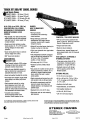
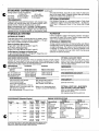
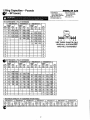
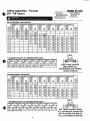
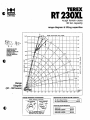
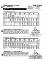
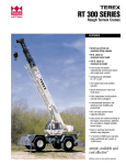
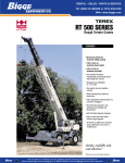
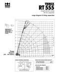
1 9 6 2 2 0 1 1 Mc ABE ECONST RUCT I ONCRANERE NT AL L I F TCHART S: 30t onT er ex 275t onGr ov e5275 165t onDema gHC400 150t onP&H9150 150t onDema gHy dr a ul i c 80t onGr ov eT M875 45met r i ct onKr upp 30t onT er e x 28t onGr ov eRT 528C 20t onGr ov eRT 58D 20t onP&HR200 18t onGr ov eRT 58C 15t onGr ov eRT 58 15t onP&HR150 7. 5t onCa s eCa r r yDec k onMa ni t e xBoomT r uc k 25t 17t onMa ni t e xBoomT r uc k M ODERN FLEET of RENTAL CRANES & EQUIPM ENT Mc Abeeha sawi der a ngeofc r a ner ent a l s er v i c est omeeta l l y ourc ons t r uc t i onneeds . Al l Mc AbeeCr a neRent a l si nc l ude f ul l yc er t iedoper a t or se x per i enc edi nea c hc r a ne' soper a t i on, l oa dl i mi t s , a ndma i nt ena nc es c hedul e . Compl et er i ggi ng, t r a ns f er , a ndt r a ns por ts er v i c esa r ea v a i l a bl e t oa s s i s tc l i ent si nt hes a f eoffloa di nga nds et t i ngofl a r gea nd hea v ymul t i moda l pa y l oa ds . Mc Abeec r a nesr a ngei ns i z et o275t onuni t s , pl usl i f tt r uc k st o 14t onuni t s . Mc Abeea l s or ent sot herc ons t r uc t i onequi pment . '•• "!: ~ 'I. .. .,·· ;i~.: ~;. LIF....ING TEREX ;1J.. " '~RT' 200/RT200XLSERIES Rough Terrain Cranes • 20-30 tons (18-27 mt) maximum lifting capacity m) or 100 It. (30.5 m) maximum boom length • 94 ft. (28.6 • ~41 ft. (43.0 m) or 147 ft. (44.8 m) maximum tip height • Four-section full power, mechanically synchronized boom with single lever control • Swingaway jib offsettabl'e 9°,'15°' or· 30°. • Two-speed main and auxiliary winches • Quick-reeving boom head and hook block • Fully independent multi-position out and down outriggers . • Environmental operator's cab optimizes load visibility and productiVity • RCI 510 load system Rated Capacity Indicator ' • Easy access for routine servicing of the engine, transmission, batteries, etc. provided by hinged lockable access doors. • Easy to read load chart books include ra.nge diagrams • 12-month or 2000 hours warranty, major weldments are 5,.years or 10,000 hours siffiple,'available and cost effective™ Machines shown may have optional equipment. · TEREX: III ZOO/RT 200XL SERIES i ugh: T~rrain Cranes . , 220/RT 200XL - 20 tons (18 mt) ~ 250/RT 250XL - 25 tons (23 mt) RT 275/RT 275XL - 27.5 tons (25 mt) RT 230/RT 230XL - 30 tons (27 mt) 94 ft. (28.6 m) or 100 ft. (30.5 m) FOUR-SECTION, FULL-POWER, MECHANICALLY. SYNCHRONIZED BOOM WITH SINGLE LEVER CONTROL • High strength, four plate construction welded inside and out with embossed side plate holes to reduce weight and increase strength. • Single boom hoist cylinder provides boom elevation of _4° to 76° for easier reeving changes and close radius operation. • Quick-reeving boom head; no need to remove wedge from socket. • 360° house lock standard. ENVIRONMENTAL -eRATOR'S CAB "-ated Capacity Indicator (RCI) system including anti-two block system with automatic function disconnects. • Deluxe six-way adjustable operator's seat has torsion bar suspension and adjustable head and arm rests. • Sound and weather insulated for comfort. • Removable front window, hinged tinted glass skylight, and sliding right-hand window. • Dash-mounted controls for swing, boom telescope, boom hoist, and single lever two-speed ma.in winch; peda.ls for swing brake and boom hoist. Foot accelerator with hand throttle. • Complete instrumentation. Environmentally-sealed rocker switches. Circuit breakerS in cab. RUGGED, EASY-TO-MANEUVER CARRIER • Box-type chassis construction with reinforcing cross members. • Range-shift type power-shift transmission with integral torque converter; neutral start; 6 speeds forward 6 reverse. • Hydraulic four-wheel power steering for 2-wheel, 4-wheel or crab steer. • Full air over hydraulic drum type brakes with air dryer. • Fully independent hydraulic outriggers may be utilized fully extended to 19 ft. (5.79 m), in their 1/2 extended position, or fully retracted. • Tail swing only 9 ft. (2.74 m). • Standard Cummins 6BT5.9 diesel engine. • Easy access for routine servicing of the engine, transmission, batteries, etc. is provided by hinged lockable access doors without the need to unbolt access panels. • Engine compartment access doors (4), and operators cab are all keyed alike. • All outside compartments and fluid reservoir access doors/caps have lockable latches or are equipped with padlock hasps. • Standard 20.5 x 25, 24 P.R. tires. • Tachometer and rear axle centering light standard. For more Infonnatlon, product demonstration, or details on purchase, lease and rental plans, please contact your local Terex Cranes Distributor. . . POWERFUL, TWO-SPEED WINCHES • 474 fpm (144 m/min) maximum line speed, 12,510 Ibs. (5673 kg) maximum line pull. Single lever control. • Integral automatic brake. • Electronic drum indicators. • Grooved drum, tapered flanges, and spring loaded cable roller for improved spooling. HIGH CAPACITY, DEPENDABLE HYDRAULIC SYSTEM • Three gear pumps driven off the transmission. Combined system capability is 113 gpm (428 Ipm). • Hydraulic reservoir with 94 gal. (355 I) capacity and full flow oil filtration system. OPTIONS INCLUDE: • 72 ft. (21.9 m) main boom. • 26 ft. or 26 to 43 ft. (7.92 or 7.92 to 13.11 m) swing-on jib. Both offset 0°,15° or 30°. • Auxiliary winch with rope. • Heater/defroster, air conditioner. • Cold weather starting aid. ·16.00 x 25,28 P.R. tires. • CAT 3116 DIT diesel engine. We reserve the right to amend these specifications at any time without notice. The only warranty applicable Is our standard written warranty applicable to the partiCUlar product and sale. We make no other warranty, expressed or Implied. ~TEREX CRANES 106 12th Street S.E. Waverly. IA 50677-9466 USA (319) 352-3920 • FAX: (319) 352·5727 E·mall: [email protected] TC-499·1 CTerex Cranes, Inc. 2001 Litho In U.S.A. Gw.terBXlift.cOOi::::> ~ 10U501T34 ·w .. I~ . _. . TEREX ~ LIFTING RT 200/RT2001l SERIES rough terrain cranes specifications STANDARD BOOM EQUIPMENT BOOM 30-94 ft. (9.23-28.78 m), four section full power boom. Telescoping is mechanically synchronized with single lever control. The synchronization system consists of a single telescope cylinder and high strength leaf chains to extend and retract the third section and tip section. Boom is high strength four plate design, welded inside and out, with anti-friction slide pads. Boom side plates are made with stamped impressions to reduce weight and increase strength. A single boom hoist cylinder provides for boom elevation of -4 to 76 degrees. All cylinders are equipped with integral hold valves. Maximum tip height is 99 ft. (30.17 m). BOOM HEAD Welded to outer section of boom. Four or five metallic load sheaves and two idler sheaves mounted on heavy duty, anti-friction bearings. Quick reeving boom head. Provisions made for side-stow jib mounting. OPTIONAL BOOM EQUIPMENT MAIN BOOM 30-72 ft. (9.23-22.19 m), three section full power boom QB 30-100 ft (9.23-30.61 m), four section full power XL Series boom. Telescoping is mechanically synchronized with single lever control. The synchronization system consists of a single telescope cylinder and high strength leaf chains to extend and retract the tip section. Either boom is high strength four plate design, welded inside and out, with anti-friction slide pads. ~oom side plates are made with stamped impressions to reduce weight and increase strength. A sin gle boom hoist cylinder provides for boom elevation of-4 to 76 degrees. All cylinders are equipped with integral hold valves. Maximum tip height with 72 ft. (22.19 m) boom option is 79 ft. (24.23 m). Maximum tip height with 100 ft. (30.61 m) XL Series boom option is 107 ft. (32.76 m). JIBS 26 ft. (7.92m) side stow swing-on one-piece lattice type jib. Single metallic sheave mounted on anti-friction bear ing. Jib is offsettable at 0°, 15°, or 30°. With 100 ft. (30.61 m) XL Series boom, maximum tip height is 130 ft. (39.62 m). 26-43 ft. (7.92-13.11 m) side-stow sWing-on lattice type jib. Single sheave mounted on anti-friction bearing. Jib is extendible to 43 ft. (13.11 m) by means of a 17 ft. (5.18 m) manual pull-out tip section, roller supported for ease of extension. Jib is offsettable at 0°, 15°, or 30°. With 100 ft. (30.61 m) XL series boom, maximum tip height is 147 ft. (44.80 m). AUXILIARY BOOM HEAD Removable auxiliary boom head has single metallic sheave mounted on anti-friction bearing. Removable pin type rope guard for quick reeving. Installs on main boom peak only. Removal is not required for jib use. HOOK BLOCK Two, three, or four metallic sheaves on anti-friction bear ings with hook and hook latch. Quick reeving design does not require removal of wedge and socket from rope. HOOK&BALL 7.0 ton (6.3 mt) top swivel ball with hook and hook latch. ... STANDARD UPPERSTRUCTURE EQUIPMENT UPPERSTRUCTURE FRAME All welded one-piece structure fabricated with high tensile strength alloy steel. Counterweight is bolted to frame. TURNTABLE CONNECTION Swing bearing is a single row, ball type, with external teeth. The swing bearing is bolted to the revolving upperstructure and welded to the carrier frame. SWING A hydraulic motor drives a double planetary reduction gear for precise and smooth swing function. Maximum swing speed (no load) is 3.0 rpm. SWING BRAKE Heavy duty multiple disc swing brake is mechanically actuated from operator's cab by foot pedal. Brake may be locked on or used as a momentary brake. A separate 360 0 mechanical house lock is also provided. RATED CAPACITY INDICATOR Rated Capacity Indicator with visual and audible warning sys~ tem and automatic function disconnects. Second generation ~ctographic display includes: boom radius, boom angle, boom :'~9th, allowable load, actual load, and percentage of allow able load registered by bar graph. Operator settable alarms prOVided for swing angle, boom length, boom angle, tip height, and work area exclusion zone. Anti-two block system includes audio/visual warning and automatic function disconnects. OPERATOR'S CAB Environmentaf cab with all steel construction, optimized visibili ty, tinted safety glass throughout, and rubber floor matting is mounted on vibration absorbing pads. The cab has a sliding door on the left side, framed sliding window on the right side, hinged tinted all glass skylight and removable front windshield to provide optimized visibility of the load open or closed. Acoustical foam padding insulates against sound and weather. STANDARD CARRIER EQUIPMENT The deluxe Six-way adjustable operator's seat is equipped with a mechanical suspension and includes head and arm rests. CONTROLS All control levers and pedals are positioned for efficient opera tion. Hand operated control levers include swing, telescope, boom hoist, winch(s), shift, vernier adjustable hand throttle and 3600 house lock. Switches include ignition, engine stop, two speed winch(s), lights, horn, windshield wipers, defroster, steering mode, parking brake, and outrigger controls. Foot con trol pedals include swing brake, boom raise, boom lower, ser vice brakes and accelerator. INSTRUMENTATION AND ACCESSORIES In-cab gauges include air pressure, bubble level, engine oil pressure, fuel, engine temperature, voltmeter, transmission tem perature, and transmission oil pressure. Indicators include low air, high water temperature/low oil pressure/high transmission temperature audio/Visual warning, low coolant audio/Visual warning, hoist drum rotation indicator(s), and Rated Capacity Indicator. Accessories include fire extinguisher; light package including headlights, tail lights, dome light, brake lights, direc tional signals, four-way hazard flashers, dome light, and back up lights with audio pulsating back-up alarm; windshield washer/ wiper and skylight wiper. R.H. and L.H. rear view mirrors; dash lights; and seat belt. Circuit breakers protect electrical circuits. HYDRAULIC CONTROL VALVES Valves are mounted on the upperstructure and are easily accessible. Valves are mechanically operated and include one four spool valve for boom elevation, telescope, main winch boost, and main winch; one single spool valve for swing. High pressure regeneration feature provides 2-speed boom extension. Quick disconnects are provided for ease of installation of pressure check gauges. OPTIONAL EQUIPMENT AUxiliary Winch • Heater/Defroster • Air Conditioner • Work Lights • Revolving Amber Light • Independent Rear Wheel Steering • Roof Mounted Spotlight • I .1 CARRIER CHASSIS High strength chassis with four-wheel drive ~nd four-wheel steer (4x4x4). Has box beam type construction with reinforc ing cross members, a precision machined turntable mounting plate and integrally welded outrigger boxes. Decking has skid-resistant surfaces, including tool storage compartment, and access steps and handles left and right side and front and rear corners. AXLES AND SUSPENSION TIRES Standard: 20.5 x 25,24 P.R. Optional: 16.00 x 25,28 P.R. SERVICE BRAKES Air over hyoraulic drum type brakes on all four wheels: 17" x 4· (43.18 x 10.2 cm) drum brakes. Rear axle is a planetary drive/steer type with total 10 in. _.~ . ,..25m) of oscillation. Automatic oscillation lockouts engage . . " len the superstructure is swung 100 in either direction. Front Ie is planetary drive/steer type, rigid mounted to the frame for increased stability. WHEELS & TIRES Disc type wheels with full tapered bead seat rim. 134 in. (3.40 m) wheelbase. PARKING BRAKE Transmission mounted spring-set, air released external caliper disk type emergency/parking brake. STEERING Hydraulic four-wheel power steering for two-wheel, four wheel, or crab steer is easily controlled by steering wheel. A rear axle centering light is provided. .~- TEREX -' -.~.. 11230 LIFTING rough terrain crane 30 ton capacity range diagram & lifting capacities --- 137' Ci) -r ~.~9. ~ o BOOM DEFLECTIONS NOT SHOWN ~~ I---, ~ I .~ 4'-5" .---l 120' I~ 140' K rl- II ~~ ~ h( :t' II F?V V :-- 130' .......... ~ DIMENSIONS ARE FOR lARGEST FACTORY FURNISHED HOOK BLOCK AND HOOK & BALL, WITH ANTI-TWO BLOCK ACTIVATED A 94'- r--- !--. II /l ~ ~ "'" ~ 61' z Cl LU ~ ~ 8m 50' 39'- 30 ~ .f it'N w72' ~ / / 'r 83'- r-- ~ ./ v~ I 0 / ~ / ~QI hz:. ;<V 1\ ~ ~ K/r.x ~ / ~ ~. ~ Hv ~ ~oJUl~O~ ~ 10' /< \-- '- :;--r-:r -, 110' ~ ~ I'... V ~ \ V\ A 1\ ~ ~ / ~ \ , \ 100' c 90' \ 80' ~ ~ o 0:: ..... 70' \ ~ ~\ ~ :---- 60' ~ v-- P\~ 1\ \ W ~ 1\ \ 5 o0:: Cl ~ / / \ V hV// V v ~ V ~ '\ J-H-H v ....V· " "'"LX / / IV /" 120' "" 1 '-{hi ""' K"- '\ VA \ ~/J' ~l( D< / K ~ :J Range Diagram (30' - 94' boom) -.......... 150' ~ J: Cl \\ ~ 50' ~ 40' lOt 30' \ 20' :\ 10' GROUND 20' .30' 40' 50' 60' 70' 80' 90' 1DO' I 10' , 20' , 30' ROTATION CRANE WORKING CONDITIONS CRANE WORKING POSITIONS kdY EL 1 REDUCTION IN MAIN BOOM CAPACITY All Jibs In Stowed Position Aux. Boom In Head Sheave HOOK BLOq K WEIGHTS Hook & Ball " 239 Lbs. Hook Block (2 Sheave) _ _680 Lbs. Hook Block (3 Sheave) _ _660 lbs. Hook Block (4 Sheave) _ _ 6~O Lbs. 0 Lbs. )100 Lbs. I , ? lST~NDAF.lD CARRIER·EQUIPMENT (continued) Turning radius to center of outside tire. (16.00 x 25) (20.5 x 25) Two-wheel: 34' 8.81" (10.50m) 34' 10.38" (10.63m) Four-wheel: 19' 3.44" (5.88m) 19' 5" (5.92m) TRANSMISSION Range-shift type power-shift transmission with integral torque converter has neutral safety start, 6 speeds forward. and 6 speeds reverse. Automatic pulsating back-up alarm. removable steel floats, each with an area of 254 in2 (1639 cm2 ), stow on the carrier frame. Complete controls and sight leveling bubble are located in the operators' cab. OPTIONAL EQUIPMENT Cold Weather Starting Aid • Immersion Heater • Pintle Hook • Clearance Lights • Front Mounted Winch - 20,000 Ibs. (9072 kg) • Independent Rear or Four Mode Rear Wheel Steer MULTI-POSITION OUT & DOWN OUTRIGGERS Fully independent hydraulic outriggers may be. utilized fully extended, in their 1/2 extended position, or fully retracted. Easily HYDRAULIC SYSTEM FILTRATION HYDRAULIC PUMPS Full flow oil filtration system with bypass protection includes a removable 60 mesh (250 micron) suction screen-type filter and 5 micron replaceable return line filter. Three gear type pumps, one single and two in tandem, driven off the transmission. Combined system capability is 113 gpm (427.7Ipm). Includes manual pump disconnect. Main and Auxiliary Winch Pump 53 gpm (200.7Ipm) @3,500 psi (246.1 kg/cm 2 ) Boom Holst, Telescope Pump 39 gpm (147.6Ipm) @3,500 psi (246.1 kg/cm 2 ) Power Steering, Outrigger and Swing Pump 21 gpm (79.5 Ipm) @ 2,500 psi (175 kg/cm 2). Always live even when pump disconnect is actuated. r HYDRAULIC RESERVOIR All steel, welded construction with internal baffles and diffuser. Provides easy access to filters and is equipped with an exter nal sight level gauge. The hydraulic tank is pressurized to aid in keeping out contaminants and in reducing potential pump cavitation. Capacity is 94 gal (355 liters). Swing-away hydraulic oil cooler is standard. MAIN WINCH SPECIFICATIONS OP"nONAL AUXILIARY WINCH Hydraulic winch with bent axis piston motor and planetary reduction provides 2-speed operation with equal speeds for power up and down. Winch is equipped with an integral automatic brake, a grooved drum with tapered flanges for improved rope spooling, a spring loaded cable roller and an electronic drum rotation indicator. HI-RANGE PERFORMANCE Lo-RANGE Max. line speed (no load) 329 fpm (100.3 rn/min) First layer 205 fpm (62.5 m/min) 2SJ7 fpm (90.5 rn/min) 475 fpm (144.8 rn/min) Fifth layer Hydraulic winch with bent axis piston motor, power up and down, equal speed, planetary reduction with integral automatic brake, cable roller, and rotation indicator. Max. line pull-first layer Max. line pull-fifth layer Permissible line pull 12,5121bs (5675 kg) 8,662 Ibs (3929 kg) 9,000 Ibs (4082 kg) 7,2981bs (3310 kg) 5,0521bs (2292 kg) PERFORMANCE (Standard Engine) High DRUM DIMENSIONS AND CAPACITY (Same as main winch) Max. Storage: 598 ft (182.3 m) 10.62 in (270 mm) drum diameter . 6th layer not a working layer 17.53 in (445 mm) length Max. Useable: 479 ft (146.0 m)'" 18.25 in (464 mm) flange dia. Cable: 5/8 in. x 450 ft (16 mm x 137.2 m) Cable type: 5/8 in. (16mm) 6x19 IWRC IPS * Based on min. flange height above top layer to comply with ANSI B30.5 right regular lay, preformed Min. breaking strength 17.9 tons (16.2 mt). Low (Same as main winch) . DRUM CAPACITY DRUM DIMENSIONS Transmission Range PERFORMANCE Forward M8Xlmum DRUM CAPACITY (Same as main winch) OPTIONAL HOIST LINE - MAIN WINCH AND OPTIONAL AUXILIARY WINCH 5/8 in. (16 mm) rotation resistant compacted strand 18x19 or 19x19. Min. breaking strength 22.6 tons (20.6 mt). ENGINE SPECIFICATIONS Maximum Tractive Gradeablll!)' Effort o Stall Gear Drive Speed 1 4-wheet 2.3 mph 3.7kmth 37,8561bs 17171 kg 112.34% 2 4-wl-eel 4.4 mph 7.1 kmth 19.2541bs 8734 kg 39.84% 3 4-wheel 12.4 mph 2O.0kmth 6,431 Ibs 29171<Q 11.10% 1 2-wl-eel 5.0 mph 8.0kmth 16.8931bs 76631<Q 34.04% 2 2-wheel 9.5 mph 15.3kmth 8,5891bs 3896 kg 15.59% 3 2-wl-eel 24.5 mph 39.4kmth 2,849Ibs 12921<Q 3.77% All performance data Is based on a gross vehicle welgtt of 52,000 Ibs (23 583 kg), 16:00 x 25 tires, 4 x 4 drive. Performance may vary due to engine performance. Gradeability data Is theoretical and is limited by tire slip, stability, or engine oil pan design. Standard Make and Model Type Bore and Stroke Displacement Max. Gross Horsepower Max. Gross Torque Aspiration AIr Alter 8ectrlcaJ System Alternator Battery Fuel Capacity. Optional Cummins 6BTA5.9 6 cylinder 4.02 x4.721n (102x 120mm) 359 cu In (5.91) 130 hp (97 kw) @ 2500 rpm 384 Ib*ft (521 N*m) @ 1200 rpm turbocharged dry type 12 volt 102 amp Caterpillar 3116 DIT 6 cylinder 4.12 X 5.01n (105 X 127 mm) 402 cu In (6.6 Q 140 hp (105 kW)@24OOrpm 4261b*ft (578 N*m) @ 1450 rpm turbocharged dry type 12 volt 115amp (2) 12\1-1000 C.CA 50 gal (1891) (2) 12\1-1600 C.CA 50 gal (1891) ,G6N.EBAL DIMENSIONS 3. Track width: 6' 7.50" (2.02m) 16:00 x 25 tires 6' 10.5" (2.10m) 20.5 x 25 tires 4. Width of carrier: 8'0" (2A4m) 16:00 x 25 tires 8'8" (2.64m) 20.5 x 25 tires l1re to frame angle 16:00 tires Approach angle: 25.1° Departure angle: 23.1° --"OTES: • . Dimensions given assume the boom is fully retracted In travel position and 16:00 x 25 tires. 20.5 tires reduce heights 1.0 (25mm). 2. Minimum ground clearance under transmission - 20.62" (0.52m) axle bowls - 19.12" (0.49m) tie rods - 20.38" (0.52m) 15.5" "C" (O.39m) 20.5 tires 24.1° 22.2° '---------t 5'·9"(1.75 m) 6.12" (O,16m) 4'-3.25" (1.30m) 11'-2" (3.40 m) 1 - - - - - - 19'-4.25" (5.90 m) - - - 1 1 - - - - - 21'·10.75" (6.67 m) - - - - - - I "0" "A" Fully extended outriggers Pinned outriggers Fully retracted outriggers 19'-0"(5.79m) 13'-2"(4.01 m) 7'-4.S" (225m) liB" 20'-6" (6.25m) 14'·S"(4.47m) S'·10.5"(2.71 m) liD" 27'-1 " (8.25m) 37'·7"(11.46m) 37'-7"(11.46m) 39'·7" (12.06m) UPPER FACING FRONT WEIGHTS & AXLE LOADS ~dd Options: 26' (7.92 m) Swing-on Jib (Stowed) lie" 15'·10"(4.83m) 26'-4" (8.03m) 26'-4" (S.03m) 2S'·4" (S.64m) Boom Length 32'(9.75m) Boom 72' (22.19m) Boom 94'(2S.7Sm) Boom 100'(30.61m) Boom "e" 12'-9.38"(3.90m) 11 '-7.5" (3.54m) 11'·7.5" (3.54m) 11 '-7.5" (3.S4m) UPPER FACING FRONT .+ 1,100 + 2,000 - 900 + 499 + 907 408 26'-43' (7.92-13.11 m) Swing-on Jib (Stowed) + 1,500 + 2,600 - 1,100 + 680 + 1179 499 Auxiliary Boom Head + 100 + 300 - 200 + 45 + 136 91 Auxiliary Winch with Wire Rope, Controls, Etc. + 115 25 + 140 + 52 11 30 ton (27.2 mt) 4 Sheave Hook Block + 655 + 1,071 - 416 + 297 + 486 189 30 ton (27.2 mt) 3 Sheave Hook Block + 670 + 1,099 - 429 + 304 + 498 194 25 ton (22.6 mt) 2 Sheave Hook Block + 682 +1,117 - 435 + 309 + 507 198 6.25 ton (5.7 mt) Hook and Ball (in tool box) + 240 + 290 50 + 109 + 130 21 Front + 45 60 15 + 20 27 7 Rear + 45 70 + 20 Pintle Hook: + 25 + + + 11 + 63 31 NOTE: Weights are for factory supplied equipment and subject to 2% variation due to manufacturing tolerances, WE RESERVE THE RIGHT TO AMEND THESE SPECIFICATIONS AT ANY TIME WITHOUT NOTICE. THE ONLY WARRANTY APPLICABLE IS OUR STANDARD WRITTEN WARRANTY APPLICABLE TO THE PARTICULAR PRODUCT AND SALE. WE MAKE NO OTHER WARRANTY, EXPRESSED OR IMPLIED. ~TEREX CRANES 106 12th Street S.E. Waverly,IA50677-9466 USA (319) 352-3920" FAX: (319) 352-5727 Gww.terexlift.cM!:::> - ~ E·mall: [email protected] TC-463-7 C Terex Cranes, Inc. 2002 Litho In U.S.A. IRS02K90 , tiftll1g Capacities - Pounds -.0' - 94' boom) 1 MODEL RT 230 COUNTERWEIGHT: W/AUX. WINCH 8900 LBS. IS ON OUTRIGGERS 85% ON TIRES 75% W/O AUX. WING H10,000 LBS. BOOM LENGTH 30-94 FT. A CAU.TION: ~o not use this spec.iflcation sheet as a load rating chart. The format . . . of data STABILITY PERCENTAGE OUTRIGGER SPREAD 19 FT. not consistent with the machine chart and may be subject to change. PCSA CLASS 10-118 ON OUTRIGGERS· FULLY EXTENDED BOOM LENGTH 30 FT LOADED LOAD BOOM OVER RADIUS ANGLE FRONT 360" (Ff) (DEG) (LB) (LB) 60,000* 60,000* 10 63.0 50,100* 50,100* 12 58.5 40,100* 40,100* 51.4 15 37.4 30,100' 30,100' 20 13.7 22,800' 22,900' 25 ** 30 35 40 45 50 55 60 65 70 75 80 85 BOOM LENGTH 39 FT BOOM LENGTH 50 IT LOADED LOADED BOOM OVER BOOM OVER LOAD ANGLE FRONT 360" ANGLE FRONT 360° RADIUS (DEG) (LB) (LB) (LB) (LB) (DEG) (Ff) 69.4 46,600' 46,600' 10 66.2 46,600' 46,600' 71.7 44,500* 44,500' 12. 61.2 40,000' 40,000' 68.0 38,500' 38,500~ 15 52.3 30,000' 30,000* 61.6 30,000' 30,000' 20 42.0 23,600' 23,600' 54.8 24,000' 24,000' 25 28.8 18,~00* 18,600 47.3 19,100* 19,100* 30 38.7 15,500 15,100 35 27.9 12.100 11,800 40 7.9 9,600 9,300 45 ** 50 .. USE THESE CHARTS ONLY WHEN ALL OUTRIGGERS ARE FULLY EXTENDED 55 60 65 70 75 80 85 OUTRIGGERS· FULLY EXTENDED BOOM LENGTH 61 FT LOADED LOAD BOOM OVER RADIUS ANGLE FRONT 360° (DEG) (LB) (LB) (Ff) 10 12 36,000' 36,000* 72.1 15 29,500* 29,500* 67.1 20 24,000* 24,000' 25 ·61.9 56.3 30 1~,4oo' 19,400* '50.4 15,700 1.5,400 35 12.400· 12,100 43.9 40 9,800 45 36.5 10,000 27.3 8,200 7,900 50 13.0 6,700 6,500 55 ** 60 65 70 75 80 BOOM LENGTH 72 FT LOADED BOOM OVER ANGLE FRONT 360" (OEG) (LB) (LB) 70.8 66.5 62,0 57.4 52.5 47.2 41.4 34.8 26.9 15.5 ** 27,400' 23.100' 19,600* 15,900 12,600 10,200 8,400 7,000 5,800 4,800 27,400* 23,100' 1~,600* 15,500 12,300 9.900 8,100. 6,800' 5,600 4,600 BOOM LENGTH 83 IT LOADED BOOM OVER ANGLE FRONT 360° (LB) (LB) (DEG) 69.8 . 66.0 62.2 58.1 53.9 49.5 44.7 39.5 33.6 26.6 17.0 ** 19,~* 15,900* 13,800* 12.000' 10,300 8,500 7,'00 6,000 5,000 4.200 3,500 BOOM LENGTH 94 FT LOADED BOOM OVER 360° ANGLE FRONT (LB) (LB) (OEG) 19,000* 15,900* 13,800* 12,000* 10,000 8,300 6.900 5,800 4,800 4,100 3,400 85 72.2 69.0 65.7 62.2 ~8.7 55.1 51.2 47.2 42.8 38.0 32.7 26.4 18.1 15,300* 13,100* 11,400* 10,000' 8,BOO* 7,900* 7,100* 6,100 5,100 4,300 3,700 3,100 2.600 15,300* 13,100* 11,400* 10,000* 8,800* 7,900' 7,000 5,800 4,900 4,200 3,500 2,9bo 2,400 LOAD RADIUS (Fl) 10 12 15 20 25 30 35 40 45 50 55 60 65 70 75 80 85 ** MAXIMUM CAPACITY AT 0 DEGREE BOOM ANGLE BOOM I£NGTH 30 FT LOAD RADIUS (FT) 'W) OVER FRONT (LB) 3600 (LB) 21 900* 21900* BOOM I£NGTH 39 FT LOAD RADIUS (FT) 34.3 OVER FRONT (LB) 3600 (LB) 15.200' 14,900 BOOM LENGTH 50 FT LOAD OVER RADIUS FRONT (FT) (LB) 45.3 9.400 BOOM I£NGTH 61 FT 3600 (LB) LOAD RADIUS (FT) OVER FRONT (LB) 360" (LB) 9.100 56.3 6,300 6,100 2 BOOM I£NGTH 72 FT LOAD RADIUS (FT) 67.3 OVER FRONT (LB) 4,400 BOOM LENGTH 83 FT 3600 (LB) LOAD RADIUS (FT) OVER FRONT (LB) 4,200 78.3 3,100 BOOM I£NGTH 94 FT 3600 (LB) LOAD RADIUS (FT) OVER FRONT (LB) 3600 (LB) 2,900 89.3 2.100 2,000 (Lifting 'Capacities - Pounds . . ~ (30' - 94' boom) CAUTION: A Do not use this specification sheet as a load rating chart. The format . . of data is not consistent with the machine chart and may be subject to change. MODEL RT 230 COU NTERWEIGHT: W/AUX. WINCH 8900 LBS. WIOAUX. WINCH 10,000 LBS. BOOM LENGTH 30-94 FT. OUTRIGGER SPREAD 19 FT. STABILITY PERCENTAGE ON OUTRIGGERS 85% ON TIRES 75% PCSA CLASS 10-118 ON OUTRIGGERS· MID POSITION BOOM LENGTH 30FT LOADED LOAD BOOM RADIUS ANGLE 360" (LB) (FT) (DEG) 60,000* 10 63.0 50,100* 12 58.5 15 38,000 51.4 21,500 20 37.4 25 13,800 13.7 ** 30 35 40 45 50 55 60 65 70 BOOM LENGTH 39 FT BO()M LENGTH 50 FT BOOM LENGTH 61 FT BOOM LENGTH 72 FT BOOM LENGTH 83 FT BOOM LENGTH 94 FT LOADED LOADED LOADED LOADED LOADED LOADED BOOM BOOM BOOM BOOM BOOM BOOM LOAD ANGLE ANGLE 360° 360" 360° ANGLE ANGLE 360° ANGLE 360° ANGLE 360" RADIUS (LB) (DEG) (LB) (DEG) (LB) (DEG) (DEG) (DEG) (LB) (LB) (LB) (DEG) (FT) 46,600* 69.4 10 66.2 46,600* 44,500* 71.7 12 38,500* 36,000* 61.2 38,700 68.0 72.1 15 22,700 67.1 52.3 61.6 23,000 23,100 22.300 70.8 20 42.0 14,700 15,200 15,400 54.8 61.9 66.5 15,600 69.8 15,300* 15,700 72.2 25 47.3 28.8 10,300 10,900 11,100 56.3 62.0 11,200 66.0 11,400 11,400 69.0 30 ** 38.7 8,000 8,300 8,400 50.4 57.4 62.2 8,500 65.7 35 8.600 27.9 6,300 5,900 43.9 52.5 58.1 6,500 6,600 6,600 62.2 40 7.9 4,400 36.5 4,800 47.2 5,000 53.9 5,100 58.7 5,200 45 ** 3,600 27.3 41.4 3,800 49.5 4,000 4,100 55.1 50 2,600 13.0 34.8 2,900 44.7 3,100 3,200 55 51.2 ** 2,100 26.9 2,300 39.~ 47.2 2,400 60 15.5 1,500 1,700 33.6 1,800 42.8 65 26.6 1,100 1,300 38.0 70 ** MAXIMUM CAPACITY AT 0 DEGREE BOOM ANGLE BOOM LENGTH BOOM LENGTH BOOM LENGTH BOOM LENGTH BOOM LENGTH BOOM LENGTH BOOM LENGTH 39 FT 61 FT 72FT 30FT 50FT 83FT 94FT LOAD LOAD LOAD LOAD LOAD LOAD LOAD RADIUS 360" RADIUS 360° RADIUS 360° RADIUS 360" RADIUS 360" RADIUS 360° RADIUS 360° (LB) (LB) (LB) (FT) (LB) (FT) (LB) (FT) (FT) (FT) (LB) (FT) (LB) (FT) 2,400 67.3 1,200 7,600 45.3 4,200 56.3 25.6 12,900 34.3 USE THESE CHARTS ONLY WHEN ALL OUTRIGGERS ARE PINNED IN MID POSITION ON OUTRIGGERS· RETRAC"rED BOOM LENGTH 30 Fr LOADED LOAD BOOM 360° RADIUS ANGLE (DEG) (LB) (FT) 32,800 10 63.0 23,600 12 58.5 15 15,800 51.4 9,100 20 37.4 13.7 5,300 25 ** 30 35 40 45 50 BOOM LENGTH 39 FT BOOM LENGTH 50 FT BOOM LENGTH 61 FT BOOM LENGTH 72 FT BOOM LENGTH 83 FT BOOM LENGTH 94 FT LOADED LOADED LOADED LOADED LOADED LOADED BOOM LOAD BOOM BOOM BOOM BOOM BOOM ANGLE 360° ANGLE 360° RADIUS ANGLE ANGLE 360° ANGLE 360° ANGLE 360° 360" (DEG) (LB) (LB) (LB) (DEG) (LB) (LB) (DEG) (FT) (LB) (DEG) (DEG) (DEG) 10 69.4 33,400 12 24,600 24,200 71.7 66.2 15 17,100 61.2 16,500 68.0 72.1 1~,9OO 10,500 10,600 20 52.3 61.6 10,300 70.8 9,800 ·67.1 7,100 69.8 7,200 72.2 7,200 25 54.8 6,700 61.9 6,900 66.5 42.0 6,200 5,000 5,100 30 4,400 4,700 62.0 4,900 66.0 69.0 28.8 3,900 47.3 56.3 ** 3,600 62.2 3,500 3,200 57.4 3,400 65.7 35 38.7 2,900 50.4 27.9 . 2,500 58.1 2,400 62.2 40 2,100 2,300 1,700 43.9 52.5 53.9 1,500 1,600 1,400 58.7 45 36.5 1,200 47.2 1,000 49.5 55.1 50 900 ** MAXIMUM CAPACITY AT 0 DEGREE BOOM ANGLE BOOM LENGTH BOOM LENGTH BOOM LENGTH 39 FT 50FT 30FT LOAD LOAD LOAD RADIUS 360* RADIUS 360° RADIUS 360° (LB) (FT) (LB) (LB) (FT) (FT) 25.6 4,900 34.3 2,400 BOOM LENGTH BOOM LENGTH BOOM LENGTH BOOM LENGTH 72FT 83FT 94 FT 61 FT LOAD LOAD LOAD LOAD 360° RADIUS 360° RADIUS 360° RADIUS 360° RADIU~ (LB) (LB) (LB) (FT) (LB) (FT) (FT) (FT) 3 USE THESE CHARTS WHEN ALL OUTRIGGER BEAMS ARE NOT IN EITHER THE MID OR FULLY EXTENDED POSITION " Lifting Capacities - Pounds -'30' - 94' boom) MODEL RT 230 CAUTION: Do not use this specificatIon sheet as a load rating chart The format . . of data is not consistent with the machine chart and may be subject to change. A COUNTERWEIGHT: STABILITY PERCENTAGE W/AUX. WINCH 6900 LBS. ON OUTRIGGERS 65% WIO AUX. WINCH 10,000 LBS. ON TIRES 75% BOOM LENGTH 3G-94 FT. PCSA CLASS 10-118 OUTRIGGER SPREAD 19 FT. SIDE STOW JIB ON FULLY EXTENDED OUTRIGGERS 26. FT OFFSETTABLE JIB 0° OFFSET 15° OFFSET 30° OFFSET LOADED LOAD LOAD LOAD BOOM RADIUS RADIUS RADIUS ANGLE (REF) (REF) 360° 3600 (REF) 3600 (DEG) (FT) (FT) (LB) (FT) (LB) .(LB) 9,100· 7,400· 75 35 40 5,600* 45 73 39 8,600* 43 6;800* 49 5,300* 43. 6,300~ 71 47 8,1.00· 52 5,000* 68 65 62 59 3600 (LB) 45 5,100* 4,800* 50 54 3,400* 3,300* 4,500* 58 64 3,200* 3,000* 300 OFFSET LOAD RADIUS (REF) 360° (LB) (FT) 62 65 68 LOADED BOOM ANGLE (DEG) 2,700* 2,700* 2,600* 2,500* 75 73 4,500* 49 54 4,100* 5,100* 4,100*' 60 3,800* 70 2,900* 65 66 3,700* fj{ 74 62 71 78 3,400* 3,000* 75 2,800* 2,700* 2,400* 4,100* 3,600* 3,400* 77 82 88 2,500* 4,600* 2,400* 84 2,800* 96 95 100 2.300* 2,300* 59 55 51 89 93 98 104 2,500* 88 95 101 108 116 2,600* 2,500* 101 107 2,100 1,700 113 119 1.300 1,000 105 110 115 121 2,000 1,600 1,300 1,000 7,300* 52 5,600* 54 6.300* 5,500* 57 62 67 73 79 3,600* 3,200* 86 55 60 64 70 51 47 76 3,500 82 43 38 32 87 93 100 2.800 2,300 1,800 1,400 91 97 102 2,600 2,200 1,800 1,400 25 106 1,000 108 1,000 II, 41 15° OFFSET LOAD RADIUS (REF) (FT) 56 61 49 4,800* 4,100* 43 FT QFFSETrABLE JIB 0° OFFSET LOAD RADIUS (REF) 3600 (FT) (LB) 2,300 1,800 1,400 82 3,100* 2,900* 2,500 2,100 1.700 1,2()0 81 89 72 71 68 47 43 38 32 25 NOTES FOR JIB CAPACITIES A. For all boom lengths less than the maxlmum with aJIb erected, the reted loads are determined by boom angle only In the appropriate column. B. For boom angle not shown, use the capacity of the next lower boom angle. C. Usted radII are for extended maIn boom only. ON TIRES 16:00 X25-28PR MAX BOOM RADIUS LENGTH (FT) (FT) 10 12 15 20. 25 30 35 40 45 50 55 60 65 30 30 39 39 50 50 20:50 X 25-24PR PICK & CARRY STATIONARY PICK & CARRY CREEP 2.5 MPH 61 61 3,800 2,700 6,100 4,900 3,800 2,700 61 72 2,000 2,000 1,500 1,500 2,000 1,500 72 1,100 1,100 1,100 50 61 1,900 1,200 6;100 4,900 6,000* 4,800* CREEP 2.5 MPH RADIUS (FT) 10 12 35;300* 29,900* 20,200* 15 27.400 24,400· 16,100· 16,600 . 16,600 11,500* 20 STATIONARY 360° STRAIGHT OVER FRONT 360" 23,600 45.900* 36,100* 26,500* 24,000 17,300 39,700· 31,100· 22,600* 19,000 13.000 27.400 25,400* 18,200· 14.100 8,000 16.200 16,200 13.200* 8,400 5,200 11,000 11,000 9,700* 5,400 7,500· 3,400 3,200 7,900 7.900 2,000 1,300 STRAIGHT OVER FRONT 44,200* 34,700* 23,700* 11.200 8,100 6,'100 4,900 3,800 3,900 2,700 2,800 .2, 100 11,200 8,300* 8,100 6,100 6,300* 5,()()()* 3,900* 4,900 3,900 2,800 3,100* 2,400* 25 30 3t1 40 45 2,100 1,800* 50 55 1,500 1;500 1,300* 60 1,200 1,200 900* 65 MAXIMUM PERMISSIBLE HOIST LINE LOAD UNEPARTS MAX. LOAD BOOM HEAD HOOK BLOCK 1 2 18,160 . 5 6 7 45,400 54,480 63,560 3-D 2-3-4-0 2·3 2·3-4 1·2·3·4 3-D 0 2-3-0 2-3-4 2-3·4·0 3 WIRE ROPE: 518· ROTATION RESISTANT COMPACTED STRAND, 18X19 OR 19X'19 MINIMUM BREAKING STRENGTH· 22..7 TONS 518· 6X19 OR 6X371WRC IPS PREFORMED RIGHT REGUlAR LAY MINIMUM BREAKING STRENGTH· 17.9 TONS 9.080 2 3 27,240 4 36,320 1-4·0 '. 1-4 ~l CECOMMENDED TIRE PRESSURE TIRE SIZE 16:00 X25·28PR 20:50 x 25-2.4PR STATIONARY 115 PSI 95 PSI CREEP 115 PSI 95 PSI 21flMPH 95 PSI 70 PSI TRAVEL 95 PSI 70·PSI 4 NOTES FOR ON TIRE CAPACITIES A. For Pick and Carry operations, boom must be centered over the front of the crane with swing brake and lock engaged. Use minimum boom point height and keep load close to ground surface. B. The load should be restrained from swinging. NO ON TIRE OPERATION WITH JIB ERECTED. C. WIthout outriggers, never maneuver the boom beyond listed load radII for applicable tires to ensure stability. D. Creep speed Is crane movement of less than 200 Ft. (61 m) In a30 minute period and not exceeding 1.0 mph(1.6 kmth). E. Refer to General Notes for additional Information. .E::~oads as shown on GENERAL NOTES OPERATION Lift Charts pertain to this machine as originally manufactured and equipped. Modifications to the machine or use of optional equipment other than that specified can result in a reduction of capacity. 2. Construction equipment can be hazardous If improperly operated or maintained. Operation and maintenance of this machine shall be in compliance with the Information in the Operator's, Parts and safety Manuals supplied with this machine. If these manuals are missing, order replacements from the manufacturer through your distributor. 3. These warnings do not constitute all of the operating conditions for the crane. The operator and job site supervision must read the OPERATORS MANUAL, CIMA SAFETY MANUAL, APPLICABLE OSHA REGULATIONS, AND SOCIETY OF MECHANICAL ENGINEERS (ASME) SAFETY STANDARDS FOR CRANES. 4. This crane and its load ratings are In accordance with POWER CRANE & SHOVEL ASSOCIATION, STANDARD NO.4, SAE CRANE LOAD STABILITY TEST CODE J765A, SAE METHOD OF TEST FOR CRANE STRUCTURE J1063 AND APPLICABLE SAFETY CODE FOR CRANES, DERRICKS AND HOISTS, ASMEIANSI 830.5. 1. CRANE LOAD RATINGS MUST NOT BE EXCEEDED. DO NOT ATTEMPT TO TIP THE CRANE TO DETERMINE ALLOWABLE LOADS. 2. When either radius or boom length, or both, are between listed values, the smaller of the two listed load ratings shall be used. 3. Do not operate at longer radii than those listed on the applicable load rating chart (cross hatched areas shown on range diagrams). 4. The boom angles shown on the capacity Chart give an approximation of the operating radius for a specified boom length. The boom angle, before loading, should be greater to account for boom deflection. It may be necessary to retract the boom if maximum boom angle is insufficient to maintain rated radius. 5. Power telescoping boom sections must be extended equally. 6. Rated loads Include the weight of hook block, slings, and auxiliary lifting devices. Their weights shall be subtracted from the listed rated load to obtain the net load that can be lifted. When lifting over the Jib the weight of any hook block, slings, and auxiliary lifting devices at the boom head must be added to the load. When jibs are erected but unused add two (2) times the weight of any hook block, slings, and auxiliary lifting devices at the jib head to the load. 7. Rated loads do not exceed 85% on outriggers or 75% on tires, of the tipping load as determined by SAE Crane Stability Test Code J765a. Structural strength ratings in chart are indicated with an asterisk (*). a. Rated loads are based on freely suspended loads. No attempt shall be made to drag a load horizontally on the ground in any direction. 9. The user shall operate at reduced ratings to allow for adverse job conditions, such as: Soft or uneven ground, out of level conditions, high winds, side loads, pendulum action, Jerking or sudden stopping of loads, hazardous conditions, experience of personnel, two machine lifts, traveling with loads, electric wires, etc., (side pull on boom or jib is hazardous). Derating of the cranes lifting capacity Is reqUired when wind speed exceeds 20 MPH. the center of the lifted load must never be allowed to move more than 3* feet off the center line of the base boom section due to the effects of wind, inertia, or any combination of the two. *"Use 2 feet off the center line of the base boom for a two section boom, 3 feet for a three section boom, or 4 feet for a four section boom." 10. The maximum load which can be telescoped is not definable, because of variations In loadings and crane maintenance, but It is permissible to attempt retraction and extension if load ratings are not exceeded. 11. Load ratings are dependent upon the crane being maintained according to manufacturer's specifications. 12.lt is recommended that load handling devices, Including hooks, and hook blocks, be kept away from boom head at all times. 13. FOR TRUCK CRANES ONLY: 360 0 -capacities apply only to machines equipped with a front outrigger jack and all five (5) outrigger Jacks properly set. If the front (5th) outrigger Jack is not properly set, the work area is restrIcted to the over side and over rear areas as shown on the Crane Working Positions diagram. Use the 3600 load ratings In the overside work areas. 14. Do not lift with outrigger beams positioned between the fully extended and Intermediate (pinned) positions. 15. Truck Cranes LlQ1 equipped with equalizing (bogie) beams between the rear axles may not be used for lifting "on tires". Truck Cranes equipped with equalizing beams and rear air suspension should "dump" the air before lifting "on tires". DEAN mONS 1. LOAD RADIUS - The horizontal distance from the axis of rotation before loading to the center of the vertical hoist line or tackle with a load 'applied. 2. LOADED BOOM ANGLE - It is the angle between the boom base section and the horizontal, after lifting the rated load at the rated radiys. The boom angle before loading should be greater to account for deflections. The loaded boom angle' combined with boom length give only an approximatron of the operating radius. 3. WORKING AREA - Areas measured in a circular arc about the centerline of rotation as shown in the diagram. 4. FREELY SUSPENDED LOAD -Load hanging free with no direct external force applied except by the hoist rope. 5. SIDE LOAD - Horizontal force applied to the lifted load either on the _~ \ . ground or in the air. NO LOAD STABIUTY LIMIT - The stability limit radius shown on the range diagrams Is the radius beyond which it is not permitted to position the boom, when the boom angle is less than the minimum shown on the applicable load chart, because the machine can overturn without any load. 7. BOOM SIDE OF CRANE - The side of the crane over which the boom is positioned when in an OVER SIDE working position. SET-UP 1. Crane load ratings are based on the crane being leveled and standing on a firm, uniform supporting surface. 2. Crane load ratings on outriggers are based on all outrigger beams being fully extended or in the case of partial extension ratings mechanically pinned In the appropriate position, and the tires free of the supporting surface. 3. Crane load ratings on tires depend on appropriate Inflation pressure and the tire conditions. caution must be exercised when increasing air pressures In tires. Consult Operator's Manual for precautions. 4. Use of jibs, Iattice-type boom extensions, or fourth section pUllouts extended Is not permitted for pick and ~rry operations. ' 5. Consult appropriate section of the Operator's and Service Manual for more exact description of holst line reeving. 6. The use of more parts of line than required by the load may result in having Insufficient rope to allow the hook block to reach the ground. 7. Properly maintained wire rope Is essential for safe crane operation. Consult Operator's Manual for proper maintenance and inspection requirements. a. When spin-resistant wire rope is used, the allowable rope loading shall be the breaking strength divided by five (5), unless otherwise specified by the wire rope manufacturer. 9. Do not elevate the boom above 600 unless the boom is positioned In-line with the crane's chassis or the outriggers are extended. Failure to observe this warning may result In loss of stability. CLAMSHELL, MAGNET, AND CONCRETE BUCKET SERVICE 1. Maximum boom length for clamshell and magnet service is 50 feet. 2. Weight of clamshell OJ magnet, plus contents are not to exceed 6,000 pounds or 90% of rated lifting capacities, whichever is less. For concrete bucket operation, weight of bucket and load must not exceed 90% of rated lifting capacity. 5 WE RESERVE THE RIGHT TO AMEND THESE SPECIFICATIONS ATANY TIME WITHOUT NOTICE. THE ONLY WARRANTY APPLICABLE IS OUR STANDARD WRITIEN WARRANTY APPLICABLE TO THE PARTICULAR PRODUCT AND SALE. WE MAKE NO OTHER WARRANTY, EXPRESSED OR IMPLIED. ~TEREX CRANES 10612th Street S.E. Waverly, IA 50677-9466 USA Giw.tereXlift.cDi:::> (319) 352·3920· FAX: (319) 352·5727 ~ E-mail: [email protected] TC-492·1 o Terex Cranes, Inc 2002 Litho In U.S.A. IR502K90 ~ ~- -c IIREX DmEi,. ' RT230n LIFTING rough terrain crane 30 ton capacity range diagra,m & lifting capacities BOOM DEFLECTIONS NOT SHOWN 143·r=--.---==:...,.....--r-I-~~~......--......--......--......--..,.---r---~-..-----r----. Gl t4'-5" ~ o f€t. --=-l " 150' j---t------ir----if-----:tr-t-~~<_t-___t-___t-__t-_+-_+-_+-__+-__t 140' 126·-.----1--. 1-----1----i---....;;:"'*"":I'o---''--II~o<---iIl+----+--;~,-----+---+---I---+----+---+-----I130' • 2-9 a~ --+---1----+---+--..., 120' DIMENSIONS ARE FOR LARGEST FACTORY FURNISHED HOOK BLOCK AND HOOK &: BALL, WITH ANTI·TWO BLOCK ACTIVATED , 00' 1----1----l1JJP--l'r-l---t---+-f---+-~:____7:..-__+~__+-_t_-__+-_t_-_1 '10' /--__/---Rl'-----,<;~oo:=-t--++-___t-__t~__r....___+-__+~_+-_+-_+-__I '00' 1---t------,~f--1"---'l~-f_+_--j.~__+_,'___+-__+-____f].r____+-_f+l....__+-__+-_I 90' o ~ o a:: (!) t---:I--JI;f------ii'P""-oo:::--lr-+-i-.-...t--T---t~:__t-__7'I''--__+-_"rl_-_++-:*T'--__+-__1 80' ~ o 70' a: w ~ I--~I---f:~f--.'~f--~-__+~,L-j.-~--'fl~_+-_+--W---+--T-+:=:-_I 60' ~ ~ (!) ~+-p...,~f----1'Ip....------i----r~---i~"""---T----t--lr-t-__+---:::::....-rT--\-__+-...,.,:---t 50' ~ 40' Range Diagram (32' - 100' boom) o' .oAl1Elill~====+--+-4--+---Il----+L--+l.--+-...J.....-+....l..--1---4---f----+---l-1 , ~--'-~:....;,1..:0·:---2'-0·--3'-0·-""4'-0·--'50-·--'60-'--'70-·-""'80-·-""'90-·- GROUND ...... '0-0-·-+'-10-'-..1..'-20-'--'-13-0-'--'1 ~@'EL J CRANE. WORKING CONDITIONS , CRANE WORKING POSITIONS REDUCTION IN MAIN BOOM CAPACITY All Jibs In Stowed Posltlon Aux. Boom In Head Sheave HOOK BLOCK WEIGHTS Hook &: Ball 239 Lbs. Hook Block (2 Sheave) _ _680 Lbs. Hook Block (3 Sheave) _ _660 Lbs. Hook Block (4 Sheave) _ _660 Lbs. OLbs. 100 Lbs. Lifting Capacities - Pounds -.,. ~ 100' boom) MODEL RT 230XL I A CAUTION: Do not use this specifrcation sheet as a load rating chart. The format of data is not consistent with the machine chart and may be subject to change. COUNTERWEIGHT: W/AUX. WINCH 8900 LBS. WIO AUX. WINCH 10,000 LBS. BOOM LENGTH 32-100 FT. OUTRIGGER SPREAD 19 FT. STABILITY PERCENTAGE ON OUTRIGGERS B5% ON TIRES 75% PCSA CLASS 10-105 ON OUTRIGGERS - FULLY EXTENDED BOOM LENGTH 32 FT LOADED BOOM OVER LOAD RADIUS ANGLE FRONT 360 (LB) (DEG) (LB) (FT) 64.8 60,000· 60,000· 10 12 60.7 49,000· 49,000· 15 54.3 42,600· 42,600· 42.0 30,100· 30,100· 20 22,500· 22,500· 25.1 25 30 35 40 45 50 55 60 65 70 75 80 85 90 0 1~ ~N BOOM LENGTH 45 FT BOOM LENGTH 56 fT LOADED LOADED BOOM OVER BOOM OVER LOAD ANGLE FRONT 360" ANGLE FRONT 360" RADIUS (DEG) (LB) (LB) (DEG) (LB) (LB) (FT) 72.2 46,600· 46,600· 10 69.5 45,200· 45,200· 73.7 43,100· 43,100· 12 65.3 39,200· 39,200· 70.4 37,200· 37,200· 15 57.9 40,000· 40,000· 64.8 30,400· 30,400· 20 49.8 23.500· 23.500· 58.9 23,900· 23,900· 25 40.6 18,500· 18,500· 52.6 18,900· 18,900· 30 29.0 14.800· 13,900 45.7 15.300· 14,400 35 5.7 11,800 10,500 37.9 12,500 11,200 40 28.2 9,900 MOO 45 7,000 12.6 8,000 50 55 60 65 70 75 80 85 90 95 USE THESE CHARTS ONLY WHEN ALL OUTRIGGERS ARE FULLY EXTENDED OUTRIGGERS - FULLY EXTENDED BOOM LENGTH.51 FT LOADED LOAD BOOM OVER RADIUS ANGLE FRONT 3600 (DEG) (FT) (LB) (La) 10 12 73.7 35,800· .35,800· 15 69.2 29,100· 29,100· 20 25 64.5 24,200· 24,200· 59.6 19,200· 19,200· 30 54.4 15,600· '14,600 35 48.9 12,700 11,400 40 9,100 42.8 10,300 45 8,400 7,400 50 35.9' 55 27.6 6,900 6.000 5,600 15.4 4,800 60 65 70 75 80 85 90 95 BOOM LENGTH 78 FT LOADED BOOM OVER ANGLE FRONT 3600 (DEG) (LB) (La) 72.3" 27,000· 68.3 22,700· 64.3 19,400· 15,800· 60.1 55.7 12,900 51.1 10,400 46.1 8,600 40.7 7,100 . 34.5 5,900 27.2 . 4,900 17.1 4,000 BOOM LENGTH.89 fT LOADED BOOM OVER ANGLE FRONT . 3600 (LB) (DEG) (LB) 27,000· 22,700· 19,400· 14,800 11,600 9,300 7,600 6,200 5,100 4,200 3,400 71.1 67.7 ,64.1 60.5 56.6 52.7 48.4 43.9 39.0· 33.4 26.9 18.2 20,400· 17,500. 15,000· 13,000 10,500 8,700 7,200 6,000 5,100 4,200 3,500 2,900 BOOM LENGTH 100FT LOADED BOOM OVER ANGLE FRONT 3600 (DEG) (LB) (La) 20,400· 17,500· 14,900 11,700 9,400 7,700 6,300 5,200 4,300 3,600 2,900 2,300 , I 73.3 70.3 67.2 64.0 60.7 57.4 53.9 50.2 46.3 42.1 37.6 32.5 26.6 19.0 3.5 15,100· 15,100· 12,900· 12,900· 11,200· 11,200· 9,800· 9,800· 8,700· 8,700· 7,800· 7,700 7,000· 6,400 6,100 5,300 5,200 4,400 4,400 3,700 3,600 3,000 3,000 2,500 2,500 2,000 2,000 1,500 1,600 1,100 LOAD RADIUS (FT) 10 12 15 20 25 30 35 40 45 50 55 60 65 70 75 80 85 90 95 ** MAXIMUM CAPACITY AT 0 DEGREE BOOM ANGLE CMlENGTH I I BOOM LENGTH 45 FT 32 F1 OVER LOAD OVER 360· S FRONT 360" RADIUS FRONT (Fl) (La) (LB) (FT) (LB) (LB) 19400· 19400· 40.1 11,700· 10,400 27.6 BOOM LENGTH 56 FT LOAD . OVER 360· ~DIUS FRONT (FT) (La) (LB) 51.1 7,600 6,600 BOOM LENGTH 67 FT LOAD RADIUS (FT) OVER FRONT (La) 62.1 5,100 2 BOOM LENGTH 78 FT 360" (LB) LOAD RADIUS (FT) OVER FRONT (La) 4,400 73.1 3,500 BOOM LENGTH 89 FT 360· (La) LOAD RADIUS (FT) OVER FRONT (La) 360· (LB) 2,900 84.1 2,400 1,900 BOOM LENGTH 100 FT LOAD OVER RADIUS FRONT (LB) (FD 95.1 1,600 360· (La) 1,100 Lifting Capacities - Pounds -'. (32' - 100' boom) I MODEL RT 230XL " A CAUTION: Do not use this specification sheet as a load rating chart. The format of data is not consistent with the machine chart and may be subject to change. COUNTERWEIGHT: W/AUX. WINCH 8900 LBS. W/O AUX. WINCH 10,000 LBS. BOOM LENGTH 32-100 FT. OUTRIGGER SPREAD 19 FT. STABILITY PERCENTAGE ON OUTRIGGERS 85% ON TIRES 75% PCSA CLASS 10-105 ON OUTRIGGERS· MID POSITION BOOM LENGTH 32 FT BOOM LENGTH 45 FT BOOM lENGTH 56FT BOOM LENGTH 67 FT BOOM LENGTH 78 FT BOOM LENGTH 89 FT BOOM LENGTH 100 FT LOADED LOADED LOADED LOADED LOADED LOADED LOADED LOAD BOOM BOOM BOo'M BOOM BOOM BOOM BOOM LOAD ANGLE 3600 ANGLE 360" 360° RADIUS ANGLE 360° ANGLE ANGLE 360° 360· ANGLE 360° ANGLE RADIUS (LB) (DEG) (LB) (DEG) (DEG) (DEG) (LB) (DEG) (LB) (LB) (DEG) (LB) (DEG) (LB) (FT) (FT) 60,000· 46,600· 10 64.8 72.2 10 45,200· 49,000· 43,100· 12 60.7 69.5 73.7 12 42,000· 39,200· 37,200· 35,800· 54.3 65.3 15 70.4 73.7 15 23,600 24,600 69.2 72.3 20 42.0 57.9 64.8 25,000 25,200 25,400 20 49.8 16,300 58.9 16,600 64.5 16,900 68.3 17,000 25.1 15.100 71.1 73.3 15,100· 25 17.100 25 40.6 11,400 52.6 11,900 59.6 64.3 12,200 67.7 12,300 70.3 30 12.100 12,400 30 29.0 8,200 45.7 8,700 54.4 60.1 9,100 64.1 9,200 35 8,900 67.2 9,300 35 5.7 5,800 6,400 6,700 6,900 37.9 48.9 55.7 60.5 7,000 64.0 7,100 40 40 45 28.2 4,700 42.8 5,100 51.1 5,300 5,400 60.7 45 56.6 5.400 12.6 3,400 35.9 46.1 50 3,800 4,000 52.7 4,100 57.4 4,200 50 27.6 2,700 40.7 3,000 55 48.4 3,100 53.9 3,200 55 15.4 60 1,900 34.5 2,100 43.9 2,300 2,400 50.2 60 27.2 1,400 1,600 39.0 46.3 1,700 65 65 ** MAXIMUM CAPACITY AT 0 DEGREE BOOM ANGLE BOOM LENGTH BOOM LENGTH BOOM LE~TH BOOM LENGTH BOOM LENGTH BOOM LENGTH BOOM LENGTH 45 FT 32 FT 56FT 67FT 78 FT 89 FT 100 FT LOAD LOAD LOAD LOAD LOAD LOAD LOAD RADIUS 360" RADIUS 3600 RADIUS 360° RADIUS 360" RADIUS 360° RADIUS 3600 RADIUS 360° (LB) (LB) (LB) (LB) (LB) (FT) (LB) (FT) (FT) (FT) (LB) (FT) (FT) (FT) 12,100 40.1 5,700 51.1 3,100 62.1 1,500 27.6 USE THESE CHARTS ONLY WHEN ALL OUTRIGGERS ARE PINNED IN MID POSITION ON OUTRIGGERS· RETRAC"rED BOOM LENGTH 32 Fr LOADED LOAD BOOM RADIUS ANGLE 360" (LB) (DEG) (FT) 34,400 64.8 10 12 24,600 60.7 15 54.3 16,300 9,200 42.0 20 5,400 25 25.1 30 35 40 45 BOOM LENGTH 45 FT BOOM LENGTH 56 FT BOOM LENGTH 67 FT BOOM LENGTH 78 FT BOOM LENGTH 89 FT BOOM LENGTH 100 Fr LOADED LOADED LOADED LOADED LOADED LOADED BOOM BOOM BOOM BOOM BOOM BOOM LOAD ANGLE ANGLE 360° ANGLE 360° 360" ANGLE 360° A~LE 360° ANGLE 360° RADIUS (DEG) (LB) (DEG) (LB) (DEG) (LB) (DEG) (LB) (DEG) (LB) (DEG) (LB) (FT) 72.2 35,200 10 69.5 25,400 25,800 73.7 12 65.3 17,200 73.7 70.4 17,800 15 17.600 57.9 10,200 10,600 69.2 10,900 64.8 10,700 72.3 20 49.8 6,300 6,800 64.5 58.9 7,000 68.3 7,100 71.1 7,200 73.3 7,300 25 40.6 4,000 52.6 4,400 59.6 4,600 4,800 64.3 67.7 4,900 70.3 5,000 30 29.0 2,300 45.7 2,700 54.4 3,000 60.1 3,200 64.1 3,300 67.2 3,400 35 5.7 1,000 37.9 1,600 48.9 1,800 55.7 2,000 2,100 2,200 60.5 64.0 40 42.8 900 51.1 1,100 1,200 56.6 60.7 1,400 45 ** MAXIMUM CAPACITY AT 0 DEGREE BOOM ANGLE BOOM LENGTH BOOM LENGTH BOOM LENGTH BOOM LENGTH BOOM LENGTH BOOM LENGTH BOOM LENGTH 45 FT 56FT 67 FT 78 FT 89 FT 100 FT LOAD LOAD LOAD LOAD LOAD LOAD 360" RADIUS 360° RADIUS 360° RADIUS 360° RADIUS 360° RADIUS 360° RADIUS 360° (LB) (LB) (LB) (LB) (FT) (FT) (LB) (fl) (LB) (LB) (FT) (FT) (FT) 3,800 40.1 900 32FT LOAD RADIUS (FT) 27.6 3 USE THESE CHARTS WHEN ALL OUTRIGGER BEAMS ARE NOT IN EITHER THE MID OR FULLY EXTENDED POSITION ~. lifting Capacities -.2' -100' boom) Pounds 1 MODEL RI 230XL A CAUTION: . . of data IS Do not use this specificatIOn sheet as a load rating chart. The format not consistent with the machrnc chnrt and may be subject to change. COUNTERWEIGHT: W/AUX. WINCH 8900 LBS. WID AUX. WINCH 10,000 LBS. BOOM LENGTH 32-100 FT. OUTRIGGER SPREAD 19 FT. STABILITY PERCENTAGE ON OUTRIGGERS 85% ON TIRES 75% PCSA CLASS 10-105 SIDE STOW JIB ON FULLY EXTENDED OUTRIGGERS 26 FT OFFSmABLE JIB 0° OFFSET LOADED LOAD BOOM RADIUS ANGLE (REF) (DEG) (F1) 43 FT OFFSETTABLE JIB 15° OFFSET 3600 (LB) LOAD RADIUS (REF) (F1) 30° OFFSET 360° (LB) LOAD RADIUS (REF) (F1) 360° (LB) 00 OFFSET LOAD RADIUS (REF) (F1) 15° OfFSET 360° (LB) LOAD RADIUS (REF) (F1) 30° OFFSET 360° (LB) LOAD RADIUS (REF) (F1) 360° (LB) LOADED BOOM ANGLE (DEG) 75 37 9,100* 43 7,400* 47 5,600* 41 5,100* 51 3,400* 59 2,700* 75 73 41 8,600* 46 6,800* 51 5,;IDO* 46 4,800* 56 3,300* 63 2,700* 73 71 44 8,100* 7,300* 6,300* 5,600* 55 60 51 58 4,500* 4,100* 61 67 71 68 65 74 80 2,600* 2,500* 5,100* MOO* 4,500* 4,100* 67 68 70 65 50 56 6,300* 50 55 60 62 61 5,500* 65 59 66 70 55 51 47 73 4,000 3,100 4,500 3,900 . n 3,200 80 2,500 86 2,000 93 1,500 1,000 84 90 96 102 43 36 100 64 3,800* 74 3,200* 3,000* 2,900* 2,500* 65 70 3,600* 79 2,800~ 85 2,400* 62 76 3,400* 85 2,900 91 2,300* 2,600 66 2,300 90 2,300 96 2,100 2,000 92 1,800 98 106 1,700 112 1,300 90 96 102 106 114 59 83· 2.700* 2,600* 2,400* 80 3.700* 3,300 2,aop 119 900 55 51 47 43 38 74 1,500 98 1,400 106 1.900 1,400 1,000 103 1,000 115 1,000 2,000 1,600 1,200 NOTES FOR JIB CAPACITIES A. For all boom lengths less than the maximum with aJib erected, the rated loads are determined by boom angle only In the appropriate column. B. For boom angle not shown, use the capaclly of the next lower boom angle. C. Listed radII are for extended main boom only. ON 1"IRES MAX BOOM RADIUS LENGTH (F1) 10 12 15 20 25 30 35 40 45 50 55 60 (F1) 32 32 32 45 45 45 56 56 56 67 67 67 16:00 X 25-28PR PICK &CARRY STATIONARY CREEP 2.5 MPH 3600 3600 STRAIGHT OVER FRONT 27,700* 44,100 20:50 X25-24PR PICK & CARRY 5fATI,ONARY CREEP 2.5 MPH RADIUS STRAIGHT OVER FRONT (F1) 10 12 34,400* 23,400* 20,600* 37,700 35,800* 26,200* 26,700* 43,600* 30,700* 22,200* 20,000* 37,900* 14,500 27,900 25,000* 17,800* 14,000 30,300* 24,000* 15,700* 15 8,200 17,500 17,500 11,100* 20 11,100. 7,800 11,100 7,900* 25 7,800 6,000 5,700* 4,400* 4,600 3,400* 2,600* 30 35 40 45 6,100 17,600 17,600 12,800' 5,400 11,200 3,400 2,000 1,300 11,200 9,300* 5,400 6,000 6,100 4;600 8,000 6,100 4,600 6,900* 5,500* 3,500 2,200 1,400 6,000 4,600 3,600 3,600 4,300" 3,400*· 800 3,600 2,900 2,700 2,700* 2,800 2,100 2,100 1,500 2,100 1,500 2,100 1,500 1,500 29,500* 19;800* 3,600 2,800 1,900* 50 2,100 1,400* 55 1,500 900* 60 MAXIMUM PERMISSIBLE HOIST LINE LOAD LINE PARTS MAX. LOAD BOOM HEAD HOOK BLOCK 1 9,080 2 0 2 18,160 3-D 3 27,240 3 3-D WIRE ROPE: 4 36,320 5 45,400 2-3-4 6 54,480 2-3-4-0 7 63,560 1-2-3-4 1-4-0 2-3-0 2-3-4 2-3-4-0 1-4 518* ROTATION RESISTANT COMfiACTED STRAND; 18X19 OR 19X19 MINIMUM BREAKING STRENGTH· 22.7 TONS 518* 6X19 OR 6X37 IWRO IPS PREFORMED RIGHT REGULAR LAy MINIMUM BREAKING STRENGTH -17.9 TONS 2-3 . OMMENDED TIRE PRESSURE . STATIONARY CREEP 21/2 MPH . 115 PSI 115 PSI 95 PSI TRAVEL 95 PSI 95 PSI 95 PSI 70 PSI 70 PSI· 4 NOTES FOR ON TIRE CAPACITIES A. For Pick and Carry operaUons, boom must be centered over the rear of the crane wlth swing brake and lock engaged. Use minimum boom point height and keep load close to ground sur1ace. Travel must be on smooth level surface. B. The load shOUld be restrained from swinging. NO ON TIRE OPERATION WITH JIB ERECTED. C. Without outriggers, nevef maneuver the boom beyond listed load radII for applicable tires to ensure stability. D. Creep speed Is crane movement of less than 200 Ft. (61m) In a30 minute period and not exceedIng 1.0 mph(1.6 kmlh). E. Refer to General Notes for additional Information. 't GENERAL NOTES \, OPERATION -"'GENERAL _ 1 . Rated loads as shown on Uft Charts pertain to this machine as originally manufactured and equipped. Modifications to the machine or use of optional equipment other than that specified can result in a reduction of capacity. 2. Construction equipment can be hazardous if improperly operated or maintained. Operation and maintenance of this machine shall be in compliance with the information in the Operato~si Parts and safety Manuals supplied with this machine. If these manuals are missing, order replacements from the manufacturer through your distributor. 3. These warnings do not constitute all of the operating conditions for the crane. The operator and job site supervision must read the OPERATORS MANUAL, CIMA SAFETY MANUAL, APPLICABLE OSHA REGULATIONS, AND SOCIETY OF MECHANICAL ENGINEERS (ASME) SAFETY STANDARDS FOR CRANES. 4. This crane and its load ratings are In accordance with POWER CRANE & SHOVELASSOCIATION, STANDARD NO.4, SAE CRANE LOAD STABIIJTY TEST CODE J765A, SAE METHOD OF TEST FOR CRANE STRUCTURE J1063 AND APPLICABLE SAFETY CODE FOR CRANES, DERRICKS AND HOISTS, ASMEIANSI 830.5. 1. CRANE LOAD RATINGS MUST NOT BE EXCEEDED. DO NOT ATTEMPT TO TIP THE CRANE TO DETERMINE ALLOWABLE LOADS. 2. When either radius or boom length, or both, are between listed values, the smaller of the two listed load ratings shall be used. 3. Do not operate at longer radii than those listed on the applicable load rating chart (cross hatched areas shown on range diagrams). 4. The boom angles shown on the Capacity Chart give an approxima tion of the operating radius for a specified boom length. The boom angle, before loading, should be greater to account for boom deflec tion. It may be necessary to retract the boom if maximum boom angle Is insufficient to maintain rated radius. 5. Power telescoping boom sections must be extended equally. 6. Rated loads include the weight of hook block, slings, and auxiliary lift ing devices. Their weights shall be subtracted from the listed rated load to obtain the net load that can be lifted. When lifting over the Jib the weight of any hook block, slings, and aux iliary lifting devices at the boom head must be added to the load. When jibs are erected but unused add two (2) times the weight of any hook block, slings, and auxiliary lifting devices at the jib head to the load. 7. Rated loads do not exceed 85% on outriggers or 75% on tires, of the tipping load as determined by SAE Crane Stability Test Code J765a. Structural strength ratings in chart are indicated with an asterisk (*). 8. Rated loads are based on freely suspended loads. No attempt shall be made to drag a load horizontally on the ground in any direction. 9. The user shall operate at reduced ratings to allow for adverse job conditions, such as: Soft or uneven ground, out of level conditions, high winds, side loads, pendulum action, jerking or sudden stopping of loads, hazardous conditions, experience of personnel, two machine lifts, traveling with loads, electric Wires, etc., (side pull on boom or jib Is hazardous). Derating of the cranes lifting capacity is required when wind speed exceeds 20 MPH. the center of the lifted load must never be allowed to move more than 3* feet off the center line of the base boom section due to the effects of wind, inertia, or any combination of the two. *"Use 2 feet off the center line of the base boom for a two section boom, 3 feet for a three section boom, or 4 feet for a four section boom." 10.The maximum load which can be telescoped is not definable, because of variations in loadings and crane maintenance, but it is permissible to attempt retraction and extension if load ratings are not exceeded. 11. Load ratings are dependent upon the crane being maintained according to manufacture~s specifications. 12.lt is recommended that load handling devices, including hooks, and hook blocks, be kept away from boom head at all times. 13.FOR TRUCK CRANES ONLY: 360 0 capacities apply only to machines equipped with a front outrigger jack and all five (5) out rigger Jacks properly set. If the front (5th) outrigger jack is not prop erly set, the work area Is restricted to the over side and over rear areas as shown on the Crane Working Positions diagram. Use the 360 0 load ratings In the oversIde work areas. 14. Do not lift with outrigger beams positioned between the fully extended and intermediate (pinned) positions. 15. Truck Cranes n.Q1 equipped with equalizing (bogie) beams between the rear axles may not be used for lifting "on tires". Truck Cranes equipped with equalizing beams and rear aIr suspension should "dump" the air before lifting "on tires". DEANITIONS 1. LOAD RADIUS - The horizontal distance from the axis of rotation before loading to the center of the vertical hoist line or tackle with a load applied. 2. LOADED BOOM ANGLE - It Is the angle between the boom base section and the horizontal, after lifting the rated load at the rated radius. The boom angle before loading should be greater to account for deflections. The loaded boom angle combined with boom length give only an approximation of the operating radius. 3. WORKING AREA - Areas measured in a circular arc about the center line of rotation as shown in the diagram. 4. FREELY SUSPENDED LOAD - Load hanging free with no direct extemal force applied except by the holst rope. 5. SIDE LOAD - Horizontal force applied to the lifted load either on the ground or in the air. - .....6. NO LOAD STABILITY LIMIT - The stability limit radiUS shown on the . , range diagrams is the radius beyond which it is not permitted to position the boom, when the boom angle is less than the minimum shown on the applicable load chart, because the machine can overturn without any load. 7. BOOM SIDE OF CRANE - The side 6f the crane over which the boom is positioned when in an OVER SIDE working position. SET-UP 1. Crane load ratings are based on the crane being leveled and standing on a firm, uniform supporting surface. 2. Crane load ratings on outriggers are based on all outrigger beams being fUlly extended or In the case of partial extension ratings mechanically pinned in the appropriate position, and the tires free of the supporting surface. 3. Crane load ratings on tires depend on appropriate Inflation pressure and the tire conditions. Caution must be exercised when increasing air pressures in tires. Consult Operato~s Manual for precautions. 4. Use of jibs, Iattice-type boom extensions, or fourth section pullouts extended is not permitted for pick and carry operations. 5. Consult appropriate section of the Operato~s and Service Manual for more exact description of hoist Iiile reeving. 6. The use of more parts of line than reqUired by the load may result in having insufficient rope to allow the hook block to reach the ground. 7. Properly maintained wire rope Is essential for safe crane operation. ConsultOperato~s Manual for proper maintenance and Inspection requirements. 8. When spin-resistant wire rope Is used, the allowable rope loading shall be the breaking strength divided by five (5), unless otherwise specified by the wire rope manufacturer. 9. Do not elevate the boom above 60 0 unless the boom Is positioned in-line with the crane's chassis or the outrlgg~rs are extended. Failure to observe this warning may result in loss of stability. CLAMSHELL, MAGNET, AND CONCRETE BUCKET SERVICE 1. Maximum boom length for clamshell and magnet service is 50 feet. 2. Weight of clamshell or magnet, plus contents are not to exceed 6,000 pounds or 90% of rated lifting capacities, whichever is less. For con crete bucket operation, weIght of bucket and load must not exceed 90% of rated lifting capacity. --c 5 .. ' I' WE RESERVE THE RIGHT TO AMEND THESE SPECIFICATIONS AT ANY TIME WITHOUT NOTICE. THE ONLY WARRANTY APPLICABLE IS OUR STAN DARD WRITTEN WARRANTY APPLICABLE TO THE PARTICULAR PRODUCT AND SALE. WE MAKE NO OTHER WARRANTY. EXPRESSED OR IMPLIED. ~TEREX 10612th Street S.E. CRANES f0 Waverly, IA 50677·9466 USA Gw.tefeXllff.co (319) 352-3920 • FAX: (319) 352-5727 ~ E-mail: [email protected] TC-513-1 C Terex Cranes, Inc 2002 LItho In U.S.A. 1R502K90