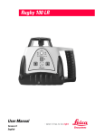
1
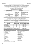
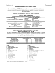
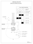
Reference A Reference A AIR ADJUSTABLE HOSE KITS Hose kit 141099 is packaged with all Air Adjustable Shocks listed in this catalog. For those vehicles equipped with G.M. Self-Leveling Systems, it may be necessary to purchase adapter kit 141248. Hose kit 140656 with separate fill valves can be installed on vehicles to allow Air Adjustable Shocks to be filled individually. REPLACEMENT AIR FITTINGS KITS Each kit packaged in individual plastic bags. KIT PART NUMBER 140701 Replacement Air Fill Valve. CONTENTS OF KIT 1 Tee Valve 1 Rubber Washer 1 Cap 2 Nuts 1 Metal Washer 1 Air Pressure Warning Circle 140721 1 Brass Fill Valve 1 Rubber Washer Necessary hardware to accomplish one 1 Cap 1 Nut complete installation; excluding hose assemblies. 1 Metal Washer 1 Air Pressure Warning Circle 141122 2 Tube Nuts 1 Tube Replacement Hose and fittings. 2 Tube Clamps 3 Tubing Clips 6 „O‟ rings G.M. SELF-LEVELING SYSTEM / HOSE KIT CROSS REFERENCE General Motors vehicles equipped with factory installed G.M. Self-Leveling Systems require an adapter hose kit to operate with our Air Adjustable. See chart below for the correct application for your vehicle. Use of conventional shock absorbers on these applications would require deactivation of the air compressor. APPLICATION AIR ADJUSTABLE NO. HOSE KIT(S) REQUIRED 1979-85 Buick Riviera 49345 141099 or 141248* 1979-85 Cadillac Eldorado 49345 141099 or 141248* 1980-85 Cadillac Seville 49345 141099 or 141248* 1979-85 Oldsmobile Toronado 49345 141099 or 141248* G.M. vehicles with electrically operated selfleveling system or vacuum operated selfleveling system (except above listings) Listed with vehicle 141099 and 141248** * 141099 and 141248 are packaged with the Air Adjustable ** 141099 is packaged with the Air Adjustable shocks. Shown for reference if replacement is required. shocks. 141248 must be purchased separately and used with hose kit packaged with shocks. No. 141099 Kit Contains: 4 - Tube Nuts 4 - Tube Clamps 10 - Packing „O‟ Rings 1 - Tube 1 - Tee Block Air Valve Fitting 1 - Valve Core 6 - Tubing Clips 1 - Valve Cap 1 - Washer 2 - Hex Nuts 1 - Seal 1 - Warning Tag 1 - Instruction Sheet *** Used in conjunction with Hose Kit # 141099. 254 No. 141248*** Kit Contains: 3 - Tube Nuts 3 - Tube Clamps 8 - Packing „O‟ Rings 2 - Tubing Clips 1 - Valve stem adapter & seal sub-assy 1 - Valve stem adapter 1 - Self-tapping screw 1 - Coupling (brass) 1 - Compression Spring 1 - Valve core 1 - Tee clip 1 - Valve cap 1 - Instruction sheet Reference A Reference A SELF LEVELING SYSTEM ELECTRONIC COMPRESSOR DEACTIVATION PROCEDURE FOR GM MODELS When installing conventional struts/shock absorbers on GM models equipped with self leveling rear suspension that uses an electronic compressor the following procedure should be used: 1. Locate height sensing unit on under body of vehicle approximately above the independent suspension/rear axle. Locate a small link connected to the independent suspension control arm/rear axle trailing arm. The upper end of this link will be connected to the electronic height sensing unit. 2. Unplug electrical wire harness from the height sensing unit. System is now deactivated. 3. Cover exposed electrical connector with tape or other suitable material and secure to underside of vehicle. 4. It is Not necessary to disconnect link to suspension control/axle trailing arm. 257 Reference C Reference C STEERING STABILIZER BOOTS BOOTS COLOR PART NUMBER RED BLACK DARK BLUE 142001 142005 142008 BOTTES DE STABILISATION DE CONDUITE BOTTES COULEUR NUMÉRO DE PIÈCE ROUGE NOIR BLEU FONÇÉ 142001 142005 142008 ZAPATOS ESTABILIZADORES DE LA DIRECCION ZAPATOS COLOR NUMERO ROJO NEGRO AZUL OSCURO 142001 142005 142008 Page 265 Reference D Reference D ELECTRONIC ADJUSTABLE SUSPENSION CONVERSION Some vehicles equipped with Electronically Adjustable Suspension can have a non-adjustable strut / shock replacement. The following is a list of those vehicles and the procedures for replacement. BUICK PARK AVENUE 1993-96 with CCR (Computer Command Ride) Remove the strut actuators Remove the CCR. It is located under the driver’s seat. o Reference GM Document VSS20000025 Remove struts and install G56718 Front and one of the following Rears: o G56707, G56726, G56903, G56906 BUICK SKYLARK 1992-94 with CCR (Computer Command Ride) Remove the shock and strut actuators Remove the CCR. It is located behind the sound insulator panel, right side. o Reference GM Document VSS20000025 Remove the shocks and struts and install G56719, G56720 front and 69749 rear. CADILLAC DEVILLE 1991-93 with CCR (Computer Command Ride) Remove the strut actuators o Reference GM Document VSS20000025 and GM Service Manual for system adjustment. Remove struts and install G56718 front and one of the following rears: o G56707, G56726, G56903, G56906 CADILLAC ELDORADO 1991-92 with CCR (Computer Command Ride) or SSS (Speed Sensitive Suspension) Remove the strut actuators o Reference GM Document VSS20000025 and GM Service Manual for system adjustment. Remove struts and install G56717 front and G56704 rear. CADILLAC SEVILLE 1991-92 with CCR (Computer Command Ride) or SSS (Speed Sensitive Suspension) Remove the strut actuators o Reference GM Document VSS20000025 and GM Service Manual for system adjustment. Remove struts and install G56717 front and G56704 rear. CHEVROLET CORVETTE 1990-96 with ERC (Electronic Ride Control) Remove the shock actuators. Unplug the ERC module. It is located in the rear cargo area. Remove the shocks and install 69811 or 75811 front and 69795 or 75795 rear. FORD PROBE 1989-92 with PRC (Programmed Ride Control) Remove the strut actuators. Unplug the PRC module. It is located under the front passenger seat. Remove the struts and install G55600 front and G55601 rear. FORD THUNDERBIRD TURBO COUPE 1987-88 with PRC (Programmed Ride Control) Remove the strut and shock actuators. Unplug the PRC module. It is located in the rear cargo area. Remove the struts and shocks and install G56504 front and 69709 rear. MAZDA MX6 GT 1988-92 with AAS (Auto Adjust Suspension) Remove the strut actuators. Unplug the AAS module. It is located in the rear cargo area. Remove the struts and install G55600 front and G55601 rear. MAZDA RX7 TURBO 1989-90 and MAZDA RX7 GXL 1986-88 with AAS (Auto Adjust Suspension) Remove the strut and shock actuators. Unplug the AAS module. It is located in the rear cargo area. Remove the struts and install G55542 front and G51031 rear. Page 266 Reference D Reference D ELECTRONIC ADJUSTABLE SUSPENSION CONVERSION MAZDA 626 1988-92 with AAS (Auto Adjust Suspension) Remove the strut actuators. Unplug the AAS module. It is located in the rear cargo area. Remove the struts and install G55600 front and G55601 rear. MAZDA 929 1988-89 with AAS (Auto Adjust Suspension) Remove the strut and shock actuators. Unplug the AAS module. It is located in the rear cargo area. Remove the struts and install G55713 front and G51192 rear. MAZDA 929 1990-91 with AAS (Auto Adjust Suspension) Remove the strut and shock actuators. Unplug the AAS module. It is located in the rear cargo area. Remove the struts and install G55716 front and G51192 rear. MERCURY COUGAR XR7 1987-88 with PRC (Programmed Ride Control) Remove the strut and shock actuators. Unplug the PRC module. It is located in the rear cargo area. Remove the struts and shocks and install G56504 front and 69709 rear. MITSUBISHI MONTERO 1992-96 with VSA (Variable Shock Absorbers) Remove the shock actuators. Unplug the module. It is located behind the left rear trim panel. Remove the shocks and install G63782 or 77782 front and G63781 or 77781 rear. NISSAN MAXIMA 1989-94 with NSS (Nissan Sonar Suspension) II Remove the strut actuators. Unplug the NSS module. It is located in the console. Remove the struts and install G55607, G55608 front and G44990 rear. NISSAN PATHFINDER 1987-95 with ASA (Adjustable Shock Absorber) Remove the shock actuators. Unplug the control switch. It is located in the console. Remove the shocks and install G63904 or 77904 front and G63492 or 77492 rear. OLDSMOBILE ACHIEVA 1992-94 with CCR (Computer Command Ride) Remove the shocks and strut actuators Remove the CCR. It is located behind the sound insulator panel, right side. o (Reference GM Document VSS20000025 Remove the shocks and struts and install G56719, G56720 front and 69749 rear. OLDSMOBILE NINETY EIGHT 1991-96 with CCR (Computer Command Ride) Remove the strut actuators. Remove the CCR. It is located under the driver’s seat. Remove struts and install G56718 front and one of the following rears: G56707, G56726, G56903, G56906 PONTIAC BONNEVILLE 1994-99 with CCR (Computer Command Ride) Remove the strut actuators. Remove the CCR. It is located under the driver’s seat. Remove struts and install G56718 front and one of the following rears: G56707, G56726, G56903, G56906 TOYOTA SUPRA from MARCH 1986-95 with TEMS (Toyota Electronic Modulated Systems) Remove the shock actuators. Unplug the TEMS module. It is located under the dash. Remove the shocks and install G51197 front and G51193 rear. Page 267 Reference H Reference H DISPOSAL OF OLD OR DEFECTIVE GAS-PRESSURIZED SHOCKS & STRUTS STORAGE OF USED SHOCK ABSORBERS AND STRUTS Used struts and shocks should be stored so Used struts and shocks can either be that any oil leakage will be properly collected. punctured to recycle the shock oil or disposed Those containers used to store this product of in a manner consistent with local or state should be labeled “USED OIL”. programs. RECYCLING OF SHOCK AND STRUT OIL 1. FOR YOUR SAFETY, ALWAYS WEAR SAFETY GLASSES AND PROTECTIVE GLOVES WHEN PUNCTURING STRUTS AND SHOCKS. 2. Securely mount the strut or shock in a vice in the horizontal position. Make sure that the piston rod is fully extended prior to drilling the unit (Fig. #1). 3. Using a 1/16” or 1/8” drill bit, drill a hole in a downward direction approximately 1.0” from the bottom of the strut or shock (Fig #2). It is important to cover the area where the hole is being drilled with a towel or some type of shield to prevent spraying gas and oil upon initial penetration of the drill bit. 4. After the gas pressure is released continue drilling into the inner cylinder of the strut or shock unit, approximately ½” deep. Drill a second ½” hole near the top of the unit. 5. Remove the strut or shock from the vice and hold it over a container to collect the used oil. Hand stroke the unit to completely purge the oil from the cylinder of the unit (Fig #3). 6. Collect all used oil, being careful not to mix this oil with any other waste or refuse. Store in DOT approved containers labeled “USED OIL”. 7. Dispose of the remaining strut or shock body and internal parts in accordance with local or state regulations (e.g., scrap metal recycler). 8. Store, dispose, and/or transport used oil in accordance with EPA regulations and your state’s used oil program. FIG. #1 FIG. #2 FIG. #3 Page 265