1
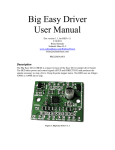
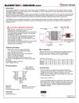
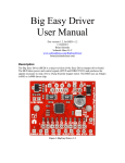
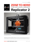
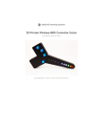
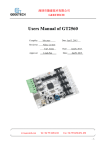
Chitu V3.1 User Manual
Compiler:Pitt Xie
Reviewer:David Yi
Approver:Sam Lin
Date: 15/08/2014
Date: 15/08/2014
Date: 15/08/2014
Copyright Declaration
The manual is only used for the purchaser. Any part of this manual
shall not be reproduced or disseminated for any purpose or in any way such
as electronic format and mechanical means or other methods, including
photocopy and record without written authorization of CBD-Tech.
Technical Supports
Please contact us if you have any interest in finished product of 3D
printed pieces, development board and related modules or is you desire for
more technical information as well as supports:
TEL: 0755-23103569
EMAIL: [email protected]
QQ: 2056288869
If you have any interest in information technology at home and abroad,
please pay attention to www.3dxmy.com , the 3D Little Ants Studio of
Technical community which is the subsidiary of the company. We will serve
you wholeheartedly.
1.Introduction
The main board of “Chitu” carries high speed microchip with 32 bit,
adopting self-developed firmware that enjoys the advantages of open source
firmware. Besides, it also carries out repeated optimization, employing SD
file configuration mode which will bring about convenient and quick
renewal.
“Chitu” mainboard matches color touch screen, enjoying simple interface
and high sensitivity. The firmware has experienced arc optimization, PID
temperature stability optimization, which is in favor of breakpoint saving
and shutdown automatically after printing. Currently, the screen interface
customization services is provided, offering you a platform to display the
company. The system supports bilingualism, the language is changed via
one key.
1.1 Parameters of Mainboard
External Dimension:150*100mm
Microprocessor : STM32
Input Voltage : 12V~24V 10~15A
Power Interface: Switching power supply or adapter
Motor Driver: Allegro A4988 (1/16 microstepping)
Motor Driven Interface: Single head motherboard has four motor interface
Double head motherboard has five motor interface
Temperature Sensor Interface: 3 paths of 100K NTC (thermistor)
2 paths of MAX6675(thermocouple)
Color Touch Screen: 2.8 or 3.5 inches of TFT
Upgraded Firmware supporting SD card (supports 8G<= FAT 16 and FAT32)
Square USB that is convenient in pull and plug,Communication Baud Rate is 115200
File Format Supported: G-code
Machine Structure Supported: XYZ type, Ultimaker type, Hbot type, Delta,Kossel type.
Recommendation of Software: Cura/Repetier-host/makerware
1.2 Interface Layout
Single-head Mainboard
Stepping Motor
X Axis
Y Axis
Z Axis
E1 Axis Hot
Bed
Hot
End
12-24V
supply
Power adapter
5V/12-24V Jumper
Hot bed fan
Thermistor
2.8 inch or
3.5 inch
Interface of
color touch
screen
E
B
USB Slave
End fan
5V
Light
bar
Hot-End
Thermocouple
(optional)
X-min
X-max
Y-min
Y-max
Z-min
Z-max
Switch of Automatic
leveling and broken
wires test etc.
SD Slot
Switch of
signal detection
Double-head Mainboard
Stepping Motor
X Axis
Y Axis
Z Axis
E1 Axis Hot
Bed
Hot
End
12-24V
supply
Power adapter
5V/12-24V Jumper
Hot bed fan
Thermistor
2.8 inch or
3.5 inch
Interface of
color touch
screen
E
B
USB Slave
End fan
5V
Light
bar
Hot-End
Thermocouple
(optional)
E2 Axis
X-min
X-max
Y-min
Y-max
Z-min
Z-max
Switch interface of selfleveling and broken
wires test etc.
Switch of Automatic
leveling and broken
wires test etc.
SD Slot
Switch of
signal detection
Hot End 2
End fan 2
Switch of Automatic
leveling and broken
wires test etc.
Thermistor E 2
Hot-End Thermocouple 2
(optional)
2.How to Use
1
Firmware Parameters Setting
Open the file of Complete machine parameters V1.2.0.gcode ( the one
with the notepad icon with file ending .gcode)with notepad.
Set the related parameter in line with machine parameters, which is shown as
follows.
Click to “save” after allocation, which is shown as follows.
Take the allocation of Complete machine parameters V1.2.0.gcode into SD
card.
SD Card
2 Update Firmware in SD Card
Plug the jumper cap of 5V/12-24V, supplying for USB. There are two kinds
of power supply.
USB(5V) Power Supply
Power Supply(12-24V)
Choose one of the above methods. Take USB supply as example, plug the
jumper cap and connect screen flat cable. The screen will light up.
After the SD card is plugged, choose the file of Complete machine parameters
V1.2.0.gcode and print. When printing is finished(about 2s-3s), the firmware
parameter is updated, shown as following figure.
3
Computer Test Printing
After the connection of all the external devices, plug the jumper cap
of 12-24V, which is shown as follows.
When the machine is initiated, it is recommended to print some small
models so as to test the validity and accuracy of parameters. Make
adjustment to parameter according to print effect until the printing is in
good condition.
3.FAQ
1.Why does not the screen light up after the connection and plugging of USB or
power supply?
Answer:
⑴ Wrong connection of power supply jumper cap.
⑵ Poor contact of flat cable on both sides of screen. It is recommended
to pull out and plug again.
2. Why does not the limit switch stop after trigger?
Answer:
⑴ Wrong setting of direction of electrical machine.
⑵ Wrong setting of structure type of limit switch in terms of machine
parameters.
3. The electrical motor does not rotate?
Answer:Wrong connection of electrical motor and false identification
between inverting and non-inverting.
4. Failure in installation of drive?
Answer:To begin with, install build-in files of folder. If it fails, it is suggested
to employ drive software like Driver Genius for one-click installation.
Driver Genius download:
http://www.driver-soft.com/download.html