1
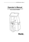
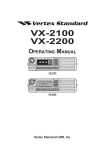
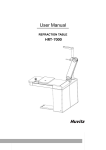
CFR-4000 Operator’s Manual Operator’s Manual CFR-4000 For Remote Tracing 1 2 CFR-4000 Operator’s Manual IMPORTANT NOTICE This product may malfunction due to electromagnetic waves caused by portable personal telephones, transceivers, radio-controlled toys, etc. Be sure to avoid having the above objects, which affect the normal operation of the product, brought near the product. The information in this publication has been carefully checked and is believed to be entirely accurate at the time of publication. HUVITZ assumes no responsibility, however, for possible errors or omissions, or for any consequences resulting from the use of the information contained herein. HUVITZ reserves the right to make changes in its products or product specifications at any time without prior notice and is not required to update this documentation to reflect such changes. © 2005 - 2013 HUVITZ Co., Ltd. 689-3, Geumjeong-dong, Gunpo-si, Gyeonggi-do, 435-862, Republic of Korea All rights are reserved. Under copyright laws, this manual may not be copied, in whole or in part, without the prior written consent of HUVITZ Co., Ltd. CFR-4000 Operator’s Manual 3 Contents IMPORTANT NOTICE ................................................................................. 2 1. Introduction............................................................................................... 5 1.1 System Configuration ......................................................................... 5 1.2 Main Features ..................................................................................... 5 1.3 Classification ....................................................................................... 5 2. Safety Information..................................................................................... 6 2.1 Introduction ........................................................................................ 6 2.2 Safety Symbols .................................................................................... 7 2.3 Environment factors ........................................................................... 8 2.4 Safety Precautions .............................................................................. 9 3. System Configuration .............................................................................. 14 3.1 Frame Reader ................................................................................... 14 3.2 Standard Accessory ........................................................................... 15 4. Installation Procedure ............................................................................. 16 5. Operation................................................................................................. 17 6. User Defined Options .............................................................................. 20 6.1 Configuration of Frame Reader ....................................................... 20 6.2 User Preferences of Frame Reader ................................................... 22 7. Using the Remote Tracing Function ........................................................ 23 7.1 Interface Specification ...................................................................... 23 7.2 Connecting to a DCS host ................................................................. 23 4 CFR-4000 Operator’s Manual 7.3 DCS Options of Frame Reader ......................................................... 25 7.4 Using the Barcode Interface for Inputting Job Number .................. 26 8. System Maintenance ................................................................................ 28 8.1 Automatic Calibration of Frame Reader .......................................... 28 Standard Accessory ...................................................................................... 32 Specification ................................................................................................ 32 System Dimension........................................................................................ 32 CFR-4000 Operator’s Manual 5 1. Introduction 1.1 System Configuration • Frame Reader (CFR-4000) • DCS Host (PC) 1.2 Main Features • Binocular 3 dimensional tracing of frames guaranteeing more precision in frame fitting. • Tracing of a demo lens or a pattern executes in two different modes, HI and LO. Especially the HI mode compensates the size by the tilting angle of the demo lens or the pattern. • SEMI-AUTO tracing mode is additionally provided for manual handling of the stylus position into the frame groove especially when the groove is lopsided. • Barcode scanner interface is supported as an option to provide a means to input job number. • Variety of DCS communication options are provided to customize it for being com pliant with different types of Lab Management Software, such as data format, points of data, angle type, communication speed, and more. 1.3 Classification • Protection against electric shock: Class I(earthed) • Installation Category: II • Pollution Degree: 2 6 CFR-4000 Operator’s Manual 2. Safety Information 2.1 Introduction Safety is everyone’s responsibility. The safe use of this equipment is largely dependent upon the installer, user, operator, and maintainer. It is imperative that personnel study and become familiar with this entire manual before attempting to install, use, clean, service or adjust this equipment and any associated accessories. It is paramount that the instructions contained in this manual are fully under stood and followed to enhance safety to the patient and the user/operator. It is for this reason that the following safety notices have been placed appropriately within the text of this manual to highlight safety related information or information requiring special emphasis. All user, operators, and maintainers must be familiar with and pay particular attention to all warning and cautions incorporated herein. ! WARNING “Warning” indicates the presence of a hazard that could result in severe personal injury, death or substantial property damage if ignored. ! NOTE “Note” describes information for the installation, operation, or maintenance of which is important but hazard related if ignored. ! CAUTION “Caution” indicates the presence of a hazard that could result in minor injury, or property damaged if ignored. CFR-4000 Operator’s Manual 7 2.2 Safety Symbols The International Electro technical Commission (IEC) has established a set of symbols for medical electronic equipment, which classify a connection or warn of any potential hazard. The classifications and symbol s are shown below. Save these instructions I and O on power switch represent ON and OFF respectively. This symbol identifies a safety note. Ensure you understand the function of this control before using it. Control function is described in the appropriate User’s or Service Manual. Identifies the point where the system safety ground is fastened to the chassis. Protective earth connected to conductive parts of Class I equipment for safety purposes. Disposal of your old appliance 1. When this crossed-out wheeled bin symbol is attached to a product it means the product is covered by the European Directive 2002/96/EC. 2. All electrical and electronic products should be disposed of separately from the municipal waste stream via designated collection facilities appointed by the government or the local authorities. 3. The correct disposal of your old appliance will help prevent potential negative consequences for the environment and human health. 4. For more detailed information about disposal of your old appliance, please contact your city office, waste disposal service or the shop where you purchased the product. 8 CFR-4000 Operator’s Manual 2.3 Environment factors Avoid the following environments for operation or storage: Where the equipment is exposed to water vapor. Don’t operate the equipment with a wet hand. Where the temperature changes extremely. - Operation Temperature: 10 ~ 40C (Humidity: 50 ~ 80%) - Storage Temperature: -20 ~ 85C (Humidity: 50 ~ 80%) Where the humidity is extremely high or there is a ventilation problem. Where equipment is exposed to chemical material or explosive gas. W here the equipment is expos ed to direct sunlight. Where it is near the heat equipment. Don’t disassemble the product or open. We aren’t responsible for it for nothing. Don’t plug the AC power cord into the outlet before the connection between devic es of the e q u i p m e n t c om p l e t e d . This can generate the defect. is CFR-4000 Operator’s Manual 9 Where the equipment is subject to excessive shocks or vibrations. Be careful not to be inserted dust, especially, metal Be careful not to close the fan located on the lateral or backside of the equipment. Pull out the power cord with holding the plug, not the cord. Avoid places where the ambient temperature falls below 10℃ or exceeds 40℃ for normal operation, or below –20℃ or exceeds 85℃ for transportation and storage. Humidity should be maintained between 50% and 80% for normal operation, transportation and storage. Avoid environments where the equipment is exposed to excessive shocks or vibrations. And also the normal operation time is as following: Operation time: short term operation max 6min 2.4 Safety Precautions This equipment has been developed and tested according to safety standards as well as national and international standards. This guarantees a very high degree of safety for this device. The legislator expects us inform the user expressively about the safety aspects in dealing with the device. The correct handling of this equipment is imperative for its safe operation. Therefore, please read carefully all instructions before switching on this device. For more detailed information, please contact our Customer Service Department or one of our authorized representatives. ① This equipment must not be used (a) in an area that is in danger of explosions 10 CFR-4000 Operator’s Manual and (b) in the presence of flammable, explosive, or volatile solvent such as alcohol, benzene or similar chemicals. ② Do not put or use this device in humid rooms. Humidity should be maintained between 50% and 80% for normal operation. Do not expose the device to water splashes, dripping water, or sprayed water. Do not place containers containing fluids, liquids, or gases on top of any electrical equipment or devices. ③ The equipment must be operated only by, or under direct supervision of a properly trained and qualified person. ④ The service technician of Huvitz or the technician authorized by Huvitz may only carry out modifications of this equipment. ⑤ Customer maintenance of this equipment may only be performed as stated in the User’s Manual and Service Manual. Any additional maintenance may only be performed by the service technician of Huvitz or the technician authorized by Huvitz. ⑥ The manufacturer is only responsible for effects on safety, reliability, and performance of this equipment when the following requirements are fulfilled: (1) The electrical installation in the respective room corresponds to the specifications stated in this manual and (2) This equipment is used, operated, and maintained according to this manual and Service Manual. ⑦ The manufacturer is not liable for damage caused by unauthorized tampering with the device(s). Such tampering will forfeit any right to claim under warranty. ⑧ This equipment may only be used together with accessories supplied by Huvitz. If the customer makes use of other accessories, use them only if their safe usability under technical aspect has been proved and confirmed by Huvitz or the manufacturer of the accessory. CFR-4000 Operator’s Manual 11 ⑨ Only person who has undergone proper training and instructions are authorized to install, use, operate, and maintain this equipment. ⑩ Keep accompanied manual(s) or technical materials, such as the User’s Manual and Service Manual, in a place easily accessible at all times for persons operating and maintaining the equipment. ⑪ Do not force cable connections. If a cable does not connect easily, be sure that the connector (plug) is appropriate for the receptacle (socket). If you cause any damage to a cable connector(s) or receptacle(s), let the damage(s) be repaired by an authorized service technician. ⑫ Please do not pull on any cable. Always hold on to the plug when disconnecting cables. ⑬ Before every operation, visually check the equipment for exterior mechanical damage(s) and for proper function. ⑭ Do not cover any ventilation grids or slits. Immediately turn off and unplug any equipment that gives off smoke, sparks, strange noises, or odors. 15 Risk of explosion if battery is replaced by an incorrect type. Dispose of used ○ batteries according to the instructions. 18 This machine might be impaired if used in a manner not specified by ○ manufacturer and this manual. ! ` WARNING • The equipment should be properly installed and operated based on the instructions on this manual. 12 CFR-4000 Operator’s Manual ! WARNING • Do not disassemble the product without the proper training. It may cause the electric shock, serious hurt during the operation or cause the malfunction of the product. • The product should be properly installed and maintained at the horizontally leveled place. Otherwise, it may affect the normal operation of the product. • Do not force on the stylus of frame reader. It may cause the malfunction of the product. • Be sure that the stylus of frame reader is not interfered with the human body or other objects during the operation. Otherwise, it may cause the hurt or malfunction of the product. ! CAUTION • When moving the equipment, first fix the stage and check whether the power supply is off. • In case of setting down the equipment, make sure not to be interfered with the obstacles. Setting down the product slowly in order to prevent the hurt of human body or damage to the product. • When moving the equipment, make sure the locking device and the screw for the cover are properly tightened. • In case of packaging the equipment, use the recommended packaging material and method in order to prevent the damage during the transportation. CFR-4000 Operator’s Manual ! 13 CAUTION • Be sure to use the standard accessories or tools provided together with the product for the maintenance. Otherwise, it may cause the malfunction of the product. 14 CFR-4000 Operator’s Manual 3. System Configuration 3.1 Frame Reader Front View Workspace for Stylus Display Window Control Panel Gripping Bar Gripper Stylus Rear View Main Switch Power Inlet & Fuse Holder Interface Terminals EDGER-1 EDGER-2 PC (upgrade console) EXTRA (reserved) CFR-4000 Operator’s Manual 3.2 Standard Accessory Standard Frame Standard Pattern Pattern Holder 15 16 CFR-4000 Operator’s Manual 4. Installation Procedure Install a Frame Reader in a sequence below. ① Remove the shock-absorbing material from the package box and pull out the Frame Reader carefully. ② Remove the shock-absorbing material from the workspace of Stylus. ③ Plug the Power Cable into the power inlet at the back of the product and turn on the power to check the initial operation. ④ If the initial operation works properly, turn off the instrument. ⑤ Connect Edger and Frame Reader by using a 9-pin D-sub Crossed Interface Cable and make sure the connectors are fixed firmly by tightening the scre ws in the cable connector. CFR-4000 Operator’s Manual 17 5. Operation Control Panel Frame Selection of Frame Material ·METAL Menu ·PL-HARD (Hard Plastic) ·PL-SOFT (Soft or flexible Plastic) Menu Selection ·CONFIG (System Configuration) ☞ Refer to the section 6.1 Configuration of Frame Reader Before tracing a frame, choose one of the material types. Usually this information is used by the edger for such as predefined size adjustment. ·CALIB (Automatic Calibration) ☞ Refer to the section 7.1 Automatic Calibration of Frame Reader Selection of Pattern Tracing Mode ·LO CURV (2D Tracing) ·HI CURV (3D Tracing) ·ETC (User Preferences) ☞ Refer to the section 6.2 User When the Pattern Holder is loaded in the Preferences of Frame Reader Frame Reader, it automatically recognizes the pattern tracing mode. HI CURV mode traces a pattern or a demo lens with size adjustment by the tilted angle of the pattern. ☞ If the tracing demo lens is curved highly, using the HI CURV mode guarantees more precision in size. 18 CFR-4000 Operator’s Manual LEFT / BOTH / RIGHT STOP LEFT / BOTH / RIGHT • BOTH : for tracing both sides of a frame and not for a demo lens. • R : for tracing right side of a frame or a right hand demo lens. • L : for tracing left side of a frame or a left hand demo lens. ☞ When it’s for a frame, holding down a tracing button for 2 seconds will executes the SEMI-AUTO tracing mode which is to aid tracing a frame with its frame groove lopsided by allowing the operator position the stylus in the center of the groove for normal tracing. Operation Tips • SEMI-AUTO mode has effect on frame-tracing only. • SEMI-AUTO mode traces a frame slower than normal tracing mode for safe tracing. Frame Tracing ① Place a frame between the upper and the lower grippers. ② In case of rather curved frames, it’s desirable to place the frame so that the center of the frame bridge is aligned with the center mark of the gripping bar. CFR-4000 Operator’s Manual 19 ③ Press the FRAME button to select a frame material among METAL, PL-HARD, and PL-SOFT. ④ Press a reading button, B for both sides, R for the right, and L for the left. Pattern Pattern Tracing Demo Lens ① Mark the horizontal axis on a pattern or a demo lens and attach a lens adapter on the axis by using a blocker. Lens Adapter ② Put the blocked pattern to the Pattern Fixing Screw Pattern Holder. ③ Press the FRAME button to select a tracing mode between LO CURV and HI CURV. ④ Press a reading button, R for the right side, and L for the left. Center Mark [Loading the Pattern Holder ] 20 CFR-4000 Operator’s Manual 6. User Defined Options 6.1 Configuration of Frame Reader • Operating the Menu Mode - Press the MENU button and then B button to enter the menu mode - Press the STOP button over 2 seconds to exit the menu mode Parameter Name Menu Category Name - MENU button: changing the selection of menu category Holding down the button for 2 seconds reverses the selection - FRAME button: selecting a configuration parameter in a menu category Holding down the button for 2 seconds reverse the selection - B button: executing a selected parameter for change Parameter Value Executed Parameter Name - R / L button: changing the value of the executed parameter CFR-4000 Operator’s Manual 21 - B button: saving the change for the executed parameter and return to the menu - STOP button: canceling the execution and return to the menu • Configuration Parameters Name Description BEEP Buzzer activation FRAME Default frame material Option List ON OFF METAL PL-HARD PL-SOFT EDGER-1 Target device for EDGER-1 port EDGER - Selecting ‘NONE’ disable the port PC NONE PROTO-1 Data communication protocol for HUVITZ DCS EDGER-1 port DCS_Z BPS-1 115200 Baud rate for EDGER -1 port 38400 9600 14400 19200 57600 EDGER-2 Target device for EDGER-2 port EDGER - Selecting ‘NONE’ disable the port PC BARCODE NONE PROTO-2 Data communication protocol EDGER-2 port BPS-2 Baud rate for EDGER -2 port for Same as ‘PROTO-1’ Same as ‘BPS-1’ 22 CFR-4000 Operator’s Manual 6.2 User Preferences of Frame Reader • Refer to 6.1 for operating the Menu Mode • User Preference Parameters Name Description Option List ID INFO Product identification VERSION Software version number DBL Bridge size input option for tracing YES single side NO Prompt option SEMI-AUTO tracing YES mode NO Low-speed-tracing option for frames YES with minimal vertical size NO SEMI-AT MINI FR FPD OFF FPD offset JOB NO. Job number reset option - Turning on the option keep the last job number even after turning off the power and the last job number is continued next time -2.99 ~ +2.99 YES NO it’s turned on TRANSMT Data transmission option for when both the edger 1 and 2 ports are turned on AUTO - AUTO option transmits automatically USER - USER option transmits through user-selecting output port EXIT Exits the menu mode CFR-4000 Operator’s Manual 23 7. Using the Remote Tracing Function 7.1 Interface Specification Version Information • Frame Reader with V1.70 or newer is required • Compatible with DCS V3.07 or its compliances RS232C Interface The basic specification of the communication port of the Frame Reader for interfacing PC follows the information below. • Baud Rate: 115200, 57600, 38400, 19200, 14400 or 9600 • Data Bit: 8 • Stop Bit: 1 • Parity: None • Flow control: None Data Format • Format: ASCII Absolute, Binary Absolute, Binary Differential, Packed Binary • Data Points: 1440, 1200, 1000, 800, 500, 400 • Radius mode: Even, Uneven • Side: Both, Right, Left • Tracing Type: Frame, Pattern 7.2 Connecting to a DCS host Before connecting the Frame Reader to any PC which is running a lab management software or a host program on it, make it sure to turn the instrument off. 24 CFR-4000 Operator’s Manual • Procedure ① Connect PC to EDGER1 port with a 9-pin DSUB crossed serial cable ② Connect a barcode reader to the EDGER2 port (barcode reader should have a connector for external power adaptor) ③ Connect a power adaptor to the barcode reader ④ Turn on the Frame Reader • Cable connection ! NOTE • In case of using a barcode scanner, it should be one with external power source as the frame reader doesn’t supply power through the port. CFR-4000 Operator’s Manual 25 7.3 DCS Options of Frame Reader To access the DCS options in the menu mode, at least one of EDGER-1 and EDGER-2 port should be set for DCS. • Procedure for Menu Execution ① Press MENU button and select the “CONFIG” menu Refer to the section 6.1 for menu operation ② Set at least one of EDGER-1 and EDGER-2 port like bellows - EDGER-1/2 : PC - PROTO-1/2 : DCS or DCS_Z ③ Change the menu category to DCS (if either of the edger port is set for DCS, the DCS menu category is activated) • DCS Parameters Name Description Option List M ID Machine Id 00 ~ 99 TIMEOUT Timeout interval for communication 10 ~ 90 seconds DATA PT Data points for DCS output 400 500 800 1000 1200 1440 FORMAT Data format for DCS output ASCII ABS = ASCII Absolute BIN ABS = Binary Absolute BIN DIF = Binary Differential PACKED BIN = Packed Binary ANGLE Angle type for DCS output ASCII ABS BIN ABS BIN DIF PACKED BIN EVEN UNEVEN 26 CFR-4000 Operator’s Manual FR-SIZE Size offset of frame data for DCS -9.99 ~ +9.99 output (in terms of circumference) PT-SIZE Size offset of pattern data for DCS -9.99 ~ +9.99 output (in terms of circumference) MIRROR FRAME Mirroring option for DCS output when YES single side is traced NO Default frame material for a job for DCS output METAL METAL = Metal PL-HARD PL-HARD = Hard Plastic PL-SOFT PL-SOFT = Soft Plastic UNDEFIN UNDEFIN = Undefined OFF OFF = Do not output frame material info. 7.4 Using the Barcode Interface for Inputting Job Number CFR-4000 with version 1.68 or newer supports barcode-scanning through the ‘EDGER-2 port’ by setting the ‘EDGER-2’ option to ‘BARCODE’. But it’s required to supply power separately to the barcode reader as the EDGER-2 port is not designed to supply power through it. This allows it to assign a job number for a new tracing job. Go to the ‘CONFIG’ menu and set the options like below. • Options for the EDGER-2 port as a barcode interface - EDGER-2: BARCODE - PROTO-2: N/A - BPS-2: 9600 (depending on the setting of a barcode scanner) • Setup for Barcode Scanner - Baud rate: 9600 (or what else bps that can be matched with the BPS-2 option in the Frame Reader) CFR-4000 Operator’s Manual 27 - Termination code: <CR>, <LF> or <CR><LF> • Inputting sequence of Job Number with a barcode scanner Press a button to execute frame or pattern- tracing Tracer beeps and prompts to scan a barcode Scan display a barcode the and number for it’ll a second on the screen Frame-tracing is automatically started after the job number input The job number is transmitted with the shape data through the EDGER-1 port The job number scanned by the barcode reader is recognized by the target device which is connected to the ‘EDGER-1’ port with the protocol DCS or the DCS_Z. 28 CFR-4000 Operator’s Manual 8. System Maintenance 8.1 Automatic Calibration of Frame Reader The Frame Reader requires calibration in following cases. • Traced shape is off axis • Traced shape has smaller or bigger size • Stylus tip is not locating the frame groove properly • Frame Reader issues height or dimension error for frames or patterns, especially when it seems that the mechanical stroke is enough for a frame or a pattern Automatic calibration for frame reader consists of three parts: Stroke, Frame, Pattern. In case of any change happened in the stylus, do the full calibration in the following sequence. • Stroke calibration • Frame calibration • Pattern calibration Otherwise, just perform frame or pattern calibration correspondingly. Frame Calibration • Purpose Detecting the frame-reading position, axis, and calibrating the size. • Procedure ① Load the standard frame which is provided as a standard accessory ② Press MENU button and select the “CALIB >> FRAME” menu Refer to the section 6.1 for menu operation ③ Press the B button two times to trigger the automatic calibration CFR-4000 Operator’s Manual 29 It traces the standard frame on both sides twice ④ If it result in any error, check if the standard frame is loaded in correct position and try again If it fails again, contact proper service engineer for maintenance • Preparation for the FRAME calibration Standard Frame • FRAME calibration menu ! NOTE • Calibration results are memorized automatically right after the completion of each calibration. • Be sure to check the related information before executing the calibration work because you cannot get back the machine to the previous status. • When a calibration seems not to be done properly, try executing the calibration again. • During the calibration, you may press the STOP button to abort the execution. 30 CFR-4000 Operator’s Manual Pattern Calibration • Purpose Detecting the pattern-reading position, axis, and calibrating the size. • Procedure ① Load the pattern holder with the standard pattern attached ② Press MENU button and select the “CALIB >> PATTERN” menu Refer to the section 6.1 for menu operation ③ Press the B button two times to trigger the automatic calibration It traces the standard pattern twice ④ If it result in any error, check if the standard pattern is loaded in correct position and try again If it fails again, contact proper service engineer for maintenance • Preparation for the PATTERN calibration Pattern Holder Standard Pattern • PATTERN calibration menu CFR-4000 Operator’s Manual 31 Stroke Calibration • Purpose Detecting the maximum dimension of possible frame and pattern reading distance. • Procedure ① Load the standard frame which is provided as a standard accessory ② Press MENU button and select the “CALIB >> STROKE” menu Refer to the section 6.1 for menu operation ③ Press the B button two times to trigger the automatic calibration ④ If it result in any error, check the movement of the stylus in every direction and try again If it fails again, contact proper service engineer for maintenance • Preparation for the STROKE calibration Standard Frame • STROKE calibration menu 32 CFR-4000 Operator’s Manual Standard Accessory Standard Frame (for Frame Reader Calibration) ············································1 Standard Pattern (for Frame Reader Calibration) ·············································1 Pattern Holder ·····················································································1 Fus e(3.15A) ·························································································2 Power Cable (Frame Reader) ···································································1 Option Barc ode Sc anner ···················································································1 9-pin Dsub Serial Cable (Crossed) ···························································· 1 L e n s A d a p t e r ········································································ 3 Specification Frame Reader Dimension 280(W) x 300(D) x 230(H) mm Tracing System 3D Binocular Weight 8 kg Power Supply AC 100~240V, 50/60Hz Power Consumption 42W(Maximum) System Dimension