1
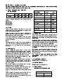
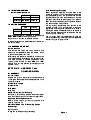
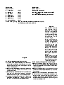
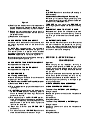
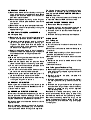
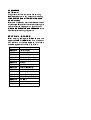
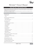
G1532 STEAKHOUSE GRILL
INSTALLATION and
SERVICING INSTRUCTIONS
These Appliances must be installed and serviced by a competent person as stipulated by the Gas
Safety (Installation & Use) Regulations.
IMPORTANT
The installer must ensure that the installation of the appliance is in conformity with these instructions and
National Regulations in force at the time of installation. Particular attention MUST be paid to -
Gas Safety (Installation & Use) Regulations
Health And Safety At Work etc. Act
Local and National Building Regulations
Fire Precautions Act
Detailed recommendations are contained in
Institute of Gas Engineers published
documents :
IGE/ UP/ 1, IGE/ UP/ 2, BS6173 and BS5440
These Appliances have been CE-marked on the basis of compliance with the Gas Appliance Directive for the
Countries, Gas Types and Pressures as stated on the Data Plate.
WARNING - TO PREVENT SHOCKS, ALL APPLIANCES WHETHER
GAS OR ELECTRIC, MUST BE EARTHED
On completion of the installation, these instructions should be left with the Engineer-in-Charge for reference
during servicing. Further to this, The Users Instructions should be handed over to the User, having had a
demonstration of the operation and cleaning of the appliance.
IT IS MOST IMPORTANT THAT THESE INSTRUCTIONS BE CONSULTED BEFORE INSTALLING AND
COMMISSIONING THIS APPLIANCE. FAILURE TO COMPLY WITH THE SPECIFIED PROCEDURES MAY
RESULT IN DAMAGE OR THE NEED FOR A SERVICE CALL.
PREVENTATIVE MAINTENANCE CONTRACT
In order to obtain maximum performance from this unit we would recommend that a Maintenance Contract be
arranged with FALCON SERVICE LINE. Visits may then be made at agreed intervals to carry out adjustments
and repairs. A quotation will be given upon request to the FALCON SERVICE LINE contact numbers below.
Falcon Foodservice Equipment
HEAD OFFICE AND WORKS
PO Box 37, Foundry Loan, Larbert.
Stirlingshire. Scotland. FK5 4PL
AFE SERVICE LINE CONTACT PHONE - 01438 751111
FAX - 01438 369900
RZZ 84 Ref. 2
SECTION 1 - INSTALLATION
UNLESS OTHERWISE STATED, PARTS WHICH HAVE BEEN PROTECTED BY THE MANUFACTURER
ARE NOT TO BE ADJUSTED BY THE INSTALLER
1.1 MODEL NUMBERS, NETT WEIGHTS
and DIMENSIONS
MODEL
G1532
WIDTH DEPTH HEIGHT WEIGHT GAS
(mm) (mm) (mm) (kg) CONN.
784
330
350
36
Rp1/2
The grill may be mounted on any of the following
options -
Bench Legs.
Floor Stand
Wall Bracket
1.2 SITING
There must be 150mm clearance all round the
appliance from any combustible wall or object liable
to damage when overheated.
There must be a minimum vertical clearance of
900mm above the top edge of the grill flue to ensure
No overheating of overlying surfaces.
A minimum clearance of 400mm from the sides
should be provided to allow removal of outer panels
for service access.
Note
The upper sections of the unit are likely to become
very hot. It should therefore be positioned in a
manner which minimises the risk of accidental
touching.
1.3 VENTILATION
The grill MUST be installed level in a well lit and
draught free position. Adequate ventilation, whether
natural or mechanical, must be provided to ensure
sufficient air for combustion and removal of combustion products, which may be harmful to health.
Recommendations for Ventilation of Catering Appliances are given in BS5440:2.
Furthermore, to ensure sufficient room ventilation,
guidance on the volume of ventilation air required for
different types of catering equipment is provided in
the following table.
For multiple installations, requirements for individual
appliances should be added together.
Installation should be made in accordance with local
and/or national regulations applying at the time.
The grill flue discharges vertically from the top of the
unit.
There must be no direct connection of the flue to a
mechanical extraction system or the outside air.
Positioning the grill below a ventilated canopy is the
most suitable arrangement.
EQUIPMENT
Range, Unit Type
Pastry Oven
Fryer
Grill
Steak Grill
Boiling Pan
Steamer
Sterilizing Sink
Bains Marie
Tea/ Coffee Machine
Ventilation Rate Required
m3/ min
ft3/min
17
17
26
17
26
17
17
14
11
8.5 - 14
1.4 GAS SUPPLY
600
600
900
600
900
600
600
500
400
300 - 500
The incoming service must be of sufficient size to
supply the full rate without excessive pressure drop.
A gas meter is connected to the service pipe by the
Gas Supplier.
An existing meter should be checked, preferably by
the Gas Supplier, to ensure that it is adequate to cope
with the rate of gas supply required. Installation pipes
should be fitted in accordance with IGE/UP/2.
The pipework size, from the meter to the unit, must
not be less than the appliance inlet connection, Rp1/4
(1/4" BSP).
An isolating cock must be located close to the
appliance (on the inlet side of the governor on Natural
Gas models) to allow shut down during an emergency
or routine service.
The installation MUST BE TESTED FOR GAS
SOUNDNESS, details of which can be found in
IGE/UP/1.
1.5 ELECTRICAL SUPPLY
Not applicable to this appliance.
1.6 WATER SUPPLY
Not applicable to this appliance.
1.7 HEAT INPUTS NATURAL and PROPANE GAS
GAS RATE
kW
Btu/hr
6.65
22,600
2.1.2 Bench Legs Assembly
1.8 INJECTOR DIAMETERS Natural and Propane Gas
NATURAL PROPANE
Main Burner 2.05mm Amal 210
Pilot Burner SIT No.30 SIT No.19
1.9 SETTING PRESSURE
NATURAL
PROPANE
mbar
15
37
inches w.g.
6
14.8
A spring loaded governor, supplied with the appliance
MUST BE FITTED to natural gas models.
No governor is required on propane models.
A pressure test point is accessible upon removal of
the control panel.
Bench legs when supplied, must be fitted to the
underside of the grill using the screws and washers
provided (see Figure 1). It is recommended that the
legs be fitted at the start of assembly and that the
operation is facilitated by placing the grill on its back.
Each foot is secureded by two fixings. Use Holes 1
and 3 as indicated in each sketch.
The leg locating brackets are then secured to the
worktop surface using woodscrews or bolts as
appropriate. The fixing hole centres are indicated in
the diagram above. The brackets should be rotated to
ensure that the threaded hole corresponds with the
side fixing hole in each leg.
The grill is then lifted into the brackets up inside the
tubular legs. Each leg is then secured to a respective
bracket using the fixings provided.
1.10 BURNER ADJUSTMENT
Burner Aeration
The burners are fitted with fixed injectors. The
aeration is adjustable by means of a screw which
is positioned at the burner inlet.
After setting the pressure, the stability of the cones
should be checked. If necessary, the aeration screw
should be adjusted to achieve satisfactory cross
lighting of the burners on both HIGH and LOW
settings. This will also prevent yellow tipping of the
flame or lift-off.
SECTION 2 - ASSEMBLY and
COMMISSIONING
2.1 ASSEMBLY
2.1.1 Grill Unit
Unpack the grill and check that all components are
undamaged. Parts supplied loose are specified in the
contents list below
Brander Drip Trough
Brander Plate
Grid Shelf
Drip Tray
Gas Governor (Natural Gas only)
Additionally, 6 refractory plaques, 4 centre support
bars of double construction and 4 end support bars.
Appliance Mounting Accessories
Details of the various grill mounting options are
detailed in section 1.1.
Individual Check Lists for Mounting Options
Bench Legs
Pack contains 4 legs and screw pack in polythene bag.
Figure 1
Wall Bracket
Floor Stand
Carton contains Carton contains
Bracket and screwpack.
A - LH Support
(1 off)
Note - Rawlplugs and woodscrews are NOT
B - Back Skirt
(2 off)
supplied
C - Top Shelf
(1 off)
2.1.4 Wall Bracket Mounting Instructions
D - RH Support
(1 off)
E - Bottom Shelf
(1 off)
F - Upper Panel
(1 off)
G - Adjustable Feet
(4 off)
and the following fixings - M5 x 10mm Hex Screws (22 off), M5 Hex Nuts (4 off)
and M5 Shakeproof Washers (18 off)
Figure 3
Figure 2
2.1.3 Floor Stand Assembly Instructions
a) Lay the two end supports (A & D) on their backs on
the floor. Slip the bottom shelf (E) over the cross
bars and secure through the side flanges into the
holes in the cross bar.
b) Slip the shelf (C) between the vertical tubes and
secure through the flanges into the holes in the
inside of the tubes.
c) Raise the partly assembled stand on to its feet and
from the rear, place the two back skirts (B)
between the rear using the nuts and bolts provided.
d) Lift the grill and position it carefully on top of the
assembled stand. Secure in position through the
two holes in the centre of the upper panel (F).
The installer must make
sure that the wall on
which the grill is to be
mounted is suitable to
carry the unit weight and
can be suitably plugged
to take No. 8
woodscrews of a
minimum length.
Using the shelf as a
template, hold it against
the wall at the required
height. Whilst
maintaining the top
surface horizontal, mark
fixing screw positions.
Remove the shelf and
drill the wall to
accomodate suitable
plugs for No. 8 screws.
Firmly secure the shelf in
position.
Place the grill on the
shelf and place screws
through holes numbered
6 to corresponding holes
in the frame of the grill.
2.1.5 Assembly of Support Bars and Plaques
a) Remove the enamelled facia by undoing the fixings
which secure it at the bottom edge. Ease the panel
forward at the bottom and lift it clear of the hidden
location screws.
b) Remove the top panel by undoing the two fixings at
the rear and slide the panel backward, clear of the
front location.
c) Remove the inner top panel to expose the burners.
d) Place the cast iron support bars between the
burner and the front and rear locating slots. Insert
the bars with the lugs facing upwards. This will
enable the plaques to be held in position against
the burner, see Figure 4.
Note
LOW FLAME position is set at factory. Re-setting is
NOT necessary.
2.5.3 Soundness Checking and Re-assembly
e) Carefully place the plaques on their support bars
with the pips pointing downward. Ensure they are
properly located and that they lay flat on the bars.
f) Replace the inner top panel and ensure that it is
properly positioned and located over the cast iron
compartment sides.
g) Replace the outer top panel.
Whilst the grill is lit, test all integral gas carrying joints
and components for soundness. Use a suitable leak
detection fluid (i.e. Soap Solution).
TURN OFF the gas control tap. REMOVE the
pressure gauge and replace the test point sealing
screw.
ENSURE THAT A GAS TIGHT JOINT IS MADE.
Re-assemble all panels and components removed
during the installation and commissioning. The drip
tray, wire grid and brander can then be placed in
position.
2.2 CONNECTION TO THE GAS SUPPLY
2.6 INSTRUCTION TO USER
Figure 4
Installation should be carried out in accordance with
the various regulations listed on the cover of this
document.
On NATURAL gas appliances, the adjustable
governor supplied, MUST be fitted to the gas circuit
and securely fixed in a position which enables
adjustment to be carried out during commissioning.
PROPANE appliances do not require a governor.
Ensure that a gas Isolating cock is fitted to the supply
at a convenient proximity to the grill.
2.3 CONNECTION TO AN ELECTRICAL SUPPLY
Not applicable to this appliance.
2.4 CONNECTION TO A WATER SUPPLY
Not applicable to this appliance.
2.5 COMMISSIONING
2.5.1 Testing and Purging
Pressure test the gas installation for soundness and
purge any air from the supply.
2.5.2 Gas Pressure and Burner Flame Adjustment
a) Remove the RH Side Panel.
b) Fit a suitable pressure gauge to the test point and
light the grill.
c) On NATURAL gas appliances, with the burner at
the FULL FLAME position, the setting pressure
should be 15mbar (6 inches w.g.). Adjust the
governor as required.
d) With the gas control in the FULL FLAME position,
check that the flame cone is approximately 30mm
in length. If necessary, adjust by means of the
aeration screw in the burner throat. Tighten the
locknut when complete.
e) Check that all burner parts CROSS LIGHT
satisfactorily.
f) Turn the control to the LOW FLAME position and
check that the flame cone reduces in length.
Hand over the Users Instruction manual. Ensure that
the user understands the procedures for lighting,
cleaning and correct use of appliance. Point out the
location of the isolating cock which may require to be
shut down in event of an emergency.
SECTION 3 - SERVICING and
CONVERSION
Important
Before carrying out any inspection, servicing or
exchange of components, turn OFF the gas at the
isolating cock and take steps to ensure that it is not
inadvertently turned on. Always remove the brander
and grid shelf.
After any maintenance task, check the appliance to
ensure that it performs correctly and carry out any
necessary adjustments as detailed in Section 1.
After carrying out any servicing or exchange of gas
carrying components -
ALWAYS CHECK FOR GAS SOUNDNESS!
3.1 GAS CONVERSION CHECK LIST
To convert from NATURAL to PROPANE gas -
Change injectors
Remove the governor and adjust the inlet pressure
accordingly
Adjust aeration
Change Data Plate
To convert from PROPANE to NATURAL gas -
Change injectors
Connect a governor and adjust the inlet pressure
accordingly
Adjust aeration
Change Data Plate
3.2 REMOVAL OF PANELS
a) Remove the enamelled front facia by undoing the
fixings which secure it at the bottom edge. Ease
the panel forward at the bottom and lift it clear of
the hidden location screws.
b) Remove the top panel by undoing out the fixings at
the rear and slide the panel backward clear of the
front location.
c) Remove the inner top panel to expose the burners.
d) Remove the side and rear panels by undoing the
appropriate fixings.
3.3 REMOVAL of PLAQUES and BURNERS
3.3.1 Plaques Only
a) Remove the drip tray, grid shelf and brander and
also the outer panels as detailed in Section 3.2.
b) Plaques may be replaced by reaching inside the
top of the grill compartment and placing your
fingers on the plaque face. Push the plaque up
carefully to dislodge it from the seating between
the bars and the support angle.
c) Carefully replace the plaque so that it is properly
seated on the bar and support angle. The plaque
should be positioned hard against the burner.
3.3.2 Burner
a) Remove the fixings at the rear and bottom of the
RH outer side panel and lift clear.
b) Remove the support bars and plaques. Place
these in a safe location until servicing is complete.
c) Undo the nut which secures the pilot pipe to the
control tap and remove the pipe.
d) Undo the nut which secures the thermocouple to
the control and remove the thermocouple.
e) Remove the igniter lead from the Piezo igniter. Lift
the burner above the injector and withdraw.
f) The pilot may now be removed from the burner by
undoing the fixings which secure it.
3.4 REMOVAL OF INJECTOR
Following removal of the burner, the injector may be
cleaned or replaced as desired. See Section 1.8 for
injector dimension details.
3.5 BURNER and INJECTOR CLEANING
Burners require to be cleaned periodically to ensure
that the ports are free from blockage. This may be
facilitated by means of wire brushing. Individual ports
may be cleared with a suitable metal instrument.
Dislodged material should then be shaken out of the
open burner end.
Should it become necessary to wash the burner(s),
ensure that they are completely dry and free from
cleaning materials before re-fitting to the appliance.
The injectors also require regular inspection and may
be cleaned with a wooden splinter or fuse wire. Hard
metal impliments MAY DAMAGE THE ORIFICE and
MUST NOT be used.
Upon re-fitting, check adjustment and flame picture
as described in Section 2.5.2 of this document.
3.6 FLAME FAILURE THERMOCOUPLE
a) Remove the RH outer side panel.
b) Undo the nut which secures the thermocouple to
the SIT pilot bracket using a 10mm spanner.
c) Undo the nut which secures the thermocouple to
the gas tap.
d) Withdraw the faulty thermocouple and replace.
3.7 GAS VALVE
3.7.1 To Remove
Proceed as follows a) Pull off the control knobs and remove the front
facia panel.
b) Undo the nut whic secures the burner feed pipe to
the control.
c) Release the pilot tubing nut from the control and
ease the pilot tube clear of it's location.
d) Remove the fixings which secure the control to the
gas pipe.
e) Manoeuvre the control to enable removal of the
thermocouple.
f ) Withdraw the control.
3.7.2 To Re-grease The Control Tap
a) Remove the fixings which retain the front securing
plate whilst holding the plate against the internal
spring pressure.
b) Carefully withdraw the plate, complete with
operating spindle.
c) Withdraw the exposed rod, spring, brass washer,
and sealing washer, taking care not to lose any
parts.
d) Withdraw the plug and clean with a soft rag and
also clean the mating surfaces in the control body.
Sparingly re-grease the plug with an approved
heat resistant grease.
Re-assemble in reverse order taking care with the
central pin assembly. Fit the spring to the pin first,
then the brass washer and finally the sealing washer.
Ensure that the sealing washer fits snugly into the
recess at the base of the plug. When re-fitting the
operating spindle, ensure that the niting pin engages
in the plug slot.
3.8 GOVERNOR
3.8.1 General
The governor will normally require little servicing.
Before proceeding with any inspection or servicing,
TURN OFF THE GAS AT THE ISOLATING COCK.
3.8.2 Procedure
Check and if necessary, clear the air breather hole of
any blockage. Ensure that the valve and seating are
clean and that the diaphragm is in good condition.
ALWAYS RE-CHECK THE GAS PRESSURE at the
Test Point after servicing the governor.
SECTION 4 - SPARES
When ordering spare parts, ALWAYS quote the
appliance TYPE and SERIAL No. This information
may be found on the data badge. A list of items
available, together with codes, is as follows Spares No.
531600010
531600040
531600050
531600070
531600075
531600110
531600140
531600150
531600410
531600420
531630010
531630015
531630110
531630120
531630190
Description
Plaque (single)
Thermocouple
Pilot Burner Body
Pilot Orifice (Natural Gas)
Pilot Orifice (Propane Gas)
Governor
Gas Control
Knob for Gas Control
Disc for Grid Shelf Handle
Handle for Grid Shelf
Injector (Natural Gas)
Injector (Propane Gas)
Grid Shelf
Brander Plate
Burner (with Pilot)