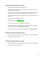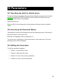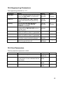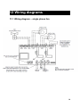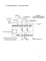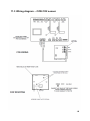
1
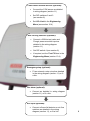
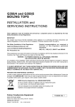
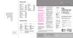
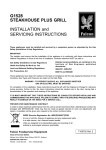
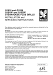
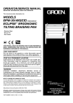
User Guide The gas interlock system for commercial kitchens Installation and Operating Instructions Tel: 01489 783783 Fax: 01489 788048 Email: [email protected] 1 www.als3.co.uk Neatafan Ltd, Unit 12, Solent Industrial Estate, Shamblehurst Lane, Hedge End, Southampton, SO30 2FX 1 Quick set-up guide......................................................... Power supply: Fuse the 230Vac power supply according to the fan currents + 2A. Maximum 25A. Connect as detailed in wiring diagram (see section 11) Gas valve: Connect 230Vac gas solenoid valve as detailed in wiring diagram (section 11) Extract fan: Connect fan as detailed in the wiring diagram (section 11) Set the fan current limits as detailed in section 9. Supply fan (if fitted): Connect fan as detailed in the wiring diagram (section 11) Set the fan current limits as detailed in section 9. 2 C2W Carbon Dioxide Sensor (optional): Connect the C2W sensor as detailed in wiring diagram (section 11) Set DIP switches 2 and 3 (see section 8) Set CO2 Limit in the Engineering Menu (see section 10.4) Gas Proving Interface (optional): Connect a 230Vac test valve and ‘Dungs’ pressure switch input as detailed in the wiring diagram (section 11) Set DIP switch 4 (see section 8) If required, set the Test Fill time in the Engineering Menu (section 10.4) Emergency stop (optional): Fit an external e-stop circuit as detailed in the wiring diagram (section 11) or fit a link. Fire alarm (optional): Connect as detailed in wiring diagram (section 11) or fit a link. Aux input (optional): Connect a flame fail detector or air flow switches as detailed in the wiring diagram (section 11), or fit a link. 3 2 Contents.............................................................................................. 1 Quick set-up guide......................................................... ....................................................................................... 2 2 Contents.............................................................................................. ................................................................. 4 3 General description..................................................... ......................................................................................... 5 4 Safety........................................................................................................ ............................................................ 5 5 Unpacking................................... ......................................................................................................................... 5 6 Operating cycle.................................................................... ................................................................................. 6 Basic operating cycle: ......................................................................................................................................... 6 6.1 Current Monitoring ........................................................................................................................................ 7 6.2 Proving.......................................................................................................................................................... 7 6.3 CO2 Detector (optional) ................................................................................................................................ 7 6.4 System Shutdown ......................................................................................................................................... 7 7 Alarms..................................................................................................... .............................................................. 8 7.1 Active Alarms ................................................................................................................................................ 8 7.2 Alarm messages ........................................................................................................................................... 8 8 DIP switch settings........................................................ ....................................................................................... 9 8.1 Location of DIP switches............................................................................................................................... 9 8.2 Default setting ............................................................................................................................................... 9 8.3 DIP switch settings ....................................................................................................................................... 9 9 Fan current limits.............................................................. .................................................................................. 10 9.1 Setting the fan currents ............................................................................................................................... 10 9.2 Setting the extract fan high current ............................................................................................................. 10 9.3 Set the extract fan low current .................................................................................................................... 11 9.4 Set the supply fan high current ................................................................................................................... 11 9.5 Set the supply fan low current..................................................................................................................... 11 10 Parameters............................................................................... ........................................................................ 12 10.1 Resetting the ALS3 to default values ........................................................................................................ 12 10.2 Accessing the Parameter Menus .............................................................................................................. 12 10.3 Editing the Parameters ............................................................................................................................. 12 10.4 Engineering Parameters ........................................................................................................................... 13 10.5 Fan Parameters ........................................................................................................................................ 13 12 Wiring diagrams............................................................. ................................................................................... 14 11.1 Wiring diagram – single phase fan............................................................................................................ 14 11.2 Wiring diagram – three phase fans ........................................................................................................... 15 11.3 Wiring diagram – C2W CO2 sensor .......................................................................................................... 16 12 Contact Details................................................................. ................................................................................ 17 4 3 General description..................................................... The ALS3 is a gas interlock system for commercial kitchens. It interlocks the gas supply with the Kitchen ventilation system. Maintaining the integrity of the kitchen ventilation system is critical for a safe working environment and this is detailed in British Standards BS6173:2009. The ALS3 is the straightforward way to help you to achieve compliance with this and other standards. All Neatafan products are provided with a comprehensive one year warranty. For more information contact Neatafan. Contact details are at the end of the manual. 4 Safety........................................................................................................ To reduce the risk of electrical shock, isolate the control panel before opening the cover. The ALS3 gas interlock is designed for indoor use as described in this manual. Using this product for any other purpose other than that for which it was designed may cause harm and will invalidate the warranty. The ALS3 must be installed by a suitably qualified engineer. If you are unsure about the safe operation of this product, contact Neatafan for advice. Contact details are at the end of this manual. 5 Unpacking................................... Neatafan takes great care to ensure your ALS3 gas interlock system reaches you in perfect condition. After unpacking, please check for any damage to the unit, retaining any packing materials should the unit need to be returned. 5 6 Operating cycle.................................................................... Basic operating cycle: Press the START button to start the fans and enable the gas. Press the STOP button at and time to return the system to the Off state. All timers () are set from the Engineering Menu Off The fans are off and the gas valves are closed. Press START Starting Fans The fans are turned on. Fan Start Fan pressure switches (optional) on AUX INPUT close Gas Proving Fill The TEST VALVE is opened for Test Fill Gas Proving Wait Proving GAS PROVE SENSOR is healthy Running GAS VALVE on. Current monitor after Holdoff Press STOP Fan Run On Run On 6 6.1 Current Monitoring The extract and supply fan currents are displayed on the screen in Amps (A). Once running, the system waits for Run On minutes for the fans to settle before monitoring the fan currents. If the fan currents exceed the Fan Hi levels, an alarm is raised. However, the gas valve will only be shut off if DIP switch 3 is OFF. Similarly, if the fan currents drop below the Fan Lo levels, an alarm is raised. However, the gas valve will only be shut off if DIP switch 3 is OFF. 6.2 Proving Gas proving is enabled by setting DIP switch 4 to ON. When the fans have started, Gas Proving Fill is displayed and the gas TEST VALVE is opened for Test Fill seconds to pressurise the installation. The system then waits for Proving seconds before checking the signal on the gas proving input. An alarm is raised if the pressure has not been maintained. 6.3 CO2 Detector (optional) When DIP switch 2 is ON and a C2W Carbon Dioxide sensor is fitted, the CO2 count in parts per million (ppm) is displayed on the screen along with the fan currents. Please note the ALS3 is only compatible with the C2W CO2 sensor. 6.4 System Shutdown Under normal operating conditions, press the STOP button to shut down the system in a controlled manner. If the emergency stop button on the ALS3 is pressed, an external E-STOP is activated or the FIRE ALARM input is activated then the GAS VALVE will shut off and the fans will immediately stop. The emergency stop buttons should only be used in an emergency. 7 7 Alarms..................................................................................................... 7.1 Active Alarms Active alarms are shown on the display. Press 2 to silence the audible alarm siren. The alarm will sound again three hours later to remind you of the fault. Press 1 to reset the system once the alarm has been cleared. 7.2 Alarm messages Alarm: E-Stop Pressed Fire Alarm Details: Either the emergency stop button the front of the ALS3 has been pressed, or an emergency stop button on the external circuit has been pressed: The external fire alarm contact is open. CO2 Level High The external sensor indicates a high CO2 level. CO2 Sensor Fault Proving Failed Sup Fan Low The external CO2 sensor is not connected or is faulty. The gas proving sensor indicated no gas pressure at the end of the proving cycle. The supply fan current is below the lower limit. Sup Fan High The supply fan current is above the upper limit. Ext Fan Low The extract fan current is below the lower limit. Ext Fan High The extract fan current is above the upper limit. Flame Failure The device connected to AUX INPUT is indicating a fault Action: Gas off Fans off Gas off Fans off Gas off Fans run-on Gas off Fans run-on Gas off Fans run Gas off Fans run Gas off Fans run Gas off Fans run Gas off Fans run Gas off Fans off 7.3 BMS relay The normally open (NO) contacts of the BMS RELAY will close on start-up and open on any fault condition. This relay can also be used as a volt-free start signal for Neatafan TC Electric Duct Heaters / Electric Heater Batteries. 8 8 DIP switch settings........................................................ 8.1 Location of DIP switches Dip switches (located inside the front panel): 8.2 Default setting On delivery all DIP switches are in the OFF position. 8.3 DIP switch settings DIP Switch: 1 OFF: (not used) ON: (not used) 2 CO2 detector not fitted. CO2 detector enabled. 3 Current alarms shut off the gas valve. Gas proving disabled Current alarms are warning only. Gas proving enabled 4 9 9 Fan current limits.............................................................. 9.1 Setting the fan currents The most straightforward way to set the current limits for the supply and extract fans is to use the inbuilt wizard. Please note the system will not run safely unless the ALS3 has been configured with the appropriate fan currents. While setting the fan currents, the system should be operated with the default current parameters. This prevents the system from shutting down and reporting spurious alarms. Carry out the following procedure to set the fan currents: 9.2 Setting the extract fan high current Observe the fan current displayed on the screen. If speed controllers are fitted, run the fan to the speed at which the current displayed is at the highest level. If dampers, baffles or any other device that restricts the airflow is fitted, set these at the level at which the current displayed is at the highest value. Access the parameter menu by holding button 3 then pressing button 4 at the same time. Enter the extract fan high passcode 2221 The display will prompt Set Extract Hi? Press 1 to accept the current reading, press 2 to cancel. The system will store the instantaneous fan current multiplied by the Over Lmt % (adjustable via the Engineering Parameters:) The extract fan high current limit can be adjusted via the Fan Parameters: 10 9.3 Set the extract fan low current Observe the fan current displayed on the screen. If speed controllers are fitted, run the fan to the speed at which the current displayed is at the lowest level. If dampers, baffles or any other device that restricts the airflow are fitted, set these at the level at which the current displayed is at the lowest value. Access the parameter menu by holding button 3 then pressing button 4 at the same time. Enter the extract fan high passcode 2211 The display will prompt Set Extract Lo? Press 1 to accept the current reading, press 2 to cancel. The system will store the instantaneous fan current multiplied by the Under Lmt % (adjustable via the Engineering Parameters:) The extract fan high current limit can be adjusted via the Fan Parameters: 9.4 Set the supply fan high current Repeat the process for setting the extract fan high current with the supply fan. The supply fan high passcode is 1122 9.5 Set the supply fan low current Repeat the process for setting the extract fan high current with the supply fan. The supply fan high passcode is 1112 11 10 Parameters............................................................................... 10.1 Resetting the ALS3 to default values To clear all settings and restore the unit to factory defaults, power up the unit while holding down both the START and STOP buttons. When the ALS3 powers up, Key Test will be shown on the display. Power down the unit. When the ALS3 is next powered up, all parameters will have returned to default values. 10.2 Accessing the Parameter Menus The parameter menus are accessed from the main operating screen. Hold button 3 then press button 4 at the same time. Enter the four digit pass code by using keys 1-4. To exit the menu, hold button 3, then press button 4 at the same time. The main operating screen will be displayed. 10.3 Editing the Parameters To edit the parameter displayed: Press 1 to increment the value. Press 2 to decrement the value. Press 3 to move to the previous parameter. Press 4 to move to the next parameter. 12 10.4 Engineering Parameters The engineering passcode is 1111. Parameter: Fan Start Test Fill Proving Run On Over Lmt Under Lmt Holdoff CO2 Limit Details: The time allowed for an optional airflow device on AUX INPUT to confirm the fans are running. The time that the gas TEST VALVE opens at the start of the gas proving cycle. The time allowed after the test fill period before the GAS PROVE SENSOR is checked The time that fans will run on after shutting off the GAS VALVE due to a high CO2 fault. The percentage above the Fan Hi current at which an alarm is generated. The percentage below the Fan Lo current at which an alarm is generated. The time which the fans are allowed to run before current monitoring begins The threshold for the CO2 level at which the gas will shut off. Range: 1 to 100 seconds Default: 10 seconds 1 to 10 seconds 2 seconds 1 to 10 seconds 10 minutes 1 to 20 minutes 2 minutes 105 to 150% 120% 75 to 95% 80% 1 to 50 minutes 15002600ppm 2 minutes Range: 0.0 to 20.0 Amps (A) 0.0 to 20.0 Amps Default: 12.0A 0.1 to 20.0 Amps 0.1 to 20.0 Amps 12.0A 2500ppm 10.5 Fan Parameters The fan parameters passcode is 4444. Parameter: S Fan Hi Details: The supply fan high current limit. S Fan Lo E Fan Hi The supply fan low current limit. (a low current of zero indicates the fan is not fitted) The extract fan high current limit. E Fan Lo The extract fan low current limit. 0.0A 0.1A 13 12 Wiring diagrams............................................................. 11.1 Wiring diagram – single phase fan 14 11.2 Wiring diagram – three phase fans 15 11.3 Wiring diagram – C2W CO2 sensor 16 12 Contact Details................................................................. Neatafan Ltd Unit 12, Solent Industrial Estate Shamblehurst Lane Hedge End Southampton SO30 2FX Tel: 01489 783783 Fax: 01489 788048 Email: [email protected] www.als3.co.uk Manual issued: 01/07/2014 17