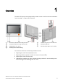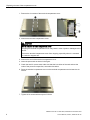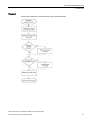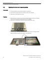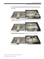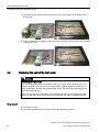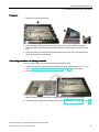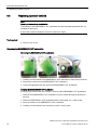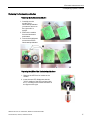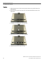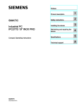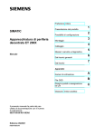
1
SIMATIC IPC277D 19" INOX PRO,
___________________
Preface
SIMATIC IFP1900 INOX PRO
1
___________________
Overview
SIMATIC
2
___________________
Safety instructions
Industrial PC, Industrial monitor
SIMATIC IPC277D 19" INOX PRO,
SIMATIC IFP1900 INOX PRO
Service Manual
Replacing the seal of the
3
___________________
compartment cover
4
___________________
Extended maintenance work
5
___________________
Accessories and spare parts
A
___________________
Technical support
03/2015
A5E35751762-AA
Legal information
Warning notice system
This manual contains notices you have to observe in order to ensure your personal safety, as well as to prevent
damage to property. The notices referring to your personal safety are highlighted in the manual by a safety alert
symbol, notices referring only to property damage have no safety alert symbol. These notices shown below are
graded according to the degree of danger.
DANGER
indicates that death or severe personal injury will result if proper precautions are not taken.
WARNING
indicates that death or severe personal injury may result if proper precautions are not taken.
CAUTION
indicates that minor personal injury can result if proper precautions are not taken.
NOTICE
indicates that property damage can result if proper precautions are not taken.
If more than one degree of danger is present, the warning notice representing the highest degree of danger will
be used. A notice warning of injury to persons with a safety alert symbol may also include a warning relating to
property damage.
Qualified Personnel
The product/system described in this documentation may be operated only by personnel qualified for the specific
task in accordance with the relevant documentation, in particular its warning notices and safety instructions.
Qualified personnel are those who, based on their training and experience, are capable of identifying risks and
avoiding potential hazards when working with these products/systems.
Proper use of Siemens products
Note the following:
WARNING
Siemens products may only be used for the applications described in the catalog and in the relevant technical
documentation. If products and components from other manufacturers are used, these must be recommended
or approved by Siemens. Proper transport, storage, installation, assembly, commissioning, operation and
maintenance are required to ensure that the products operate safely and without any problems. The permissible
ambient conditions must be complied with. The information in the relevant documentation must be observed.
Trademarks
All names identified by ® are registered trademarks of Siemens AG. The remaining trademarks in this publication
may be trademarks whose use by third parties for their own purposes could violate the rights of the owner.
Disclaimer of Liability
We have reviewed the contents of this publication to ensure consistency with the hardware and software
described. Since variance cannot be precluded entirely, we cannot guarantee full consistency. However, the
information in this publication is reviewed regularly and any necessary corrections are included in subsequent
editions.
Siemens AG
Division Digital Factory
Postfach 48 48
90026 NÜRNBERG
GERMANY
A5E35751762-AA
Ⓟ 05/2015 Subject to change
Copyright © Siemens AG 2015.
All rights reserved
Preface
Validity
This document applies to the following devices in combination with the Compact Operating
Instructions of the same name:
● SIMATIC IPC277D 19" INOX PRO, article numbers 6AV7484-4AB00-xxxx
● SIMATIC IFP1900 Touch INOX PRO, article numbers 6AV7484-6AB00-xxxx
"xxxx" stands for the variant key of the article number.
Conventions
The term "device" is also used instead of the product designation in this document.
Figures
This document contains figures of the device described. The figures can deviate from the
particularities of the delivered device.
Steps in the figures are identified with process numbers according to the sequence in which
they have to be executed:
,
,
, ...
A device for stand mounting is shown as an example in the figures. The steps can be
executed in the same way for a device for support arm mounting.
SIMATIC IPC277D 19" INOX PRO, SIMATIC IFP1900 INOX PRO
Service Manual, 03/2015, A5E35751762-AA
3
Table of contents
Preface ................................................................................................................................................... 3
1
Overview ................................................................................................................................................ 5
2
Safety instructions .................................................................................................................................. 6
3
Replacing the seal of the compartment cover .......................................................................................... 7
4
Extended maintenance work ................................................................................................................... 9
4.1
Overview ................................................................................................................................ 10
4.2
Opening the device and loosening cables ............................................................................. 12
4.3
Replacing the seal of the rear panel ...................................................................................... 14
4.4
Replacing operator controls ................................................................................................... 16
4.5
Changing the mounting type .................................................................................................. 19
4.6
Fastening the rear panel ........................................................................................................ 21
5
Accessories and spare parts ..................................................................................................................23
A
Technical support ..................................................................................................................................25
A.1
Service and support ............................................................................................................... 25
SIMATIC IPC277D 19" INOX PRO, SIMATIC IFP1900 INOX PRO
4
Service Manual, 03/2015, A5E35751762-AA
1
Overview
The INOX PRO devices are equipped with operator controls on the front and are intended for
"stand mounting" or "support arm mounting".
①
②
③
④
Illuminated pushbutton "left" with green LED
Illuminated pushbutton "right" with red LED
EMERGENCY OFF button
⑤
⑥
⑦
Terminal compartment cover with seal
Rear panel with seal
Mounting kit for support arm mounting
Mounting kit for stand mounting
This document describes the following maintenance work:
● Replacing the seal of the compartment cover
● Replacing defective operator controls in the device front and LEDs
● Replacing the seal of the rear panel
● Changing the mounting type, which means converting a device for stand mounting into a
device for support arm mounting and vice versa.
SIMATIC IPC277D 19" INOX PRO, SIMATIC IFP1900 INOX PRO
Service Manual, 03/2015, A5E35751762-AA
5
2
Safety instructions
WARNING
Extended maintenance work may only be carried out by qualified and correspondingly
trained personnel
The Service Manual describes extended maintenance work, among other things. The
device is opened as part of the extended maintenance work with work to take place on the
wiring or on electronic components inside the device. Injuries or material damage may
result if the work is not carried out correctly.
The maintenance work described in the Service Manual may only be carried out by
qualified specialist personnel who have been trained correspondingly by Siemens.
WARNING
IP66K degree of protection
The device has IP66K degree of protection when it is closed. If the seals are not inserted
correctly during maintenance work or if the device is not closed properly, IP66K degree of
protection is no longer guaranteed. Humidity may penetrate the device. The result may be
damage to the device and personal injury.
Make sure you follow the instructions in this document precisely when replacing the seals.
Make sure that the seals are inserted correctly and that the covers are fastened properly.
Storage and transport
NOTICE
Damage from condensation
If the device is subjected to extreme changes in temperature during transportation, for
example, in the case of cold weather, moisture can built up on and in the device. Moisture
can result in short-circuits in electrical circuits.
The device no longer works correctly.
In case of condensation, you need to store the device in a dry place and slowly warm it up
to room temperature. However, do not expose the device to direct heat radiation. Wait
12 hours before you switch on the device.
SIMATIC IPC277D 19" INOX PRO, SIMATIC IFP1900 INOX PRO
6
Service Manual, 03/2015, A5E35751762-AA
Replacing the seal of the compartment cover
3
WARNING
IP66K degree of protection
The device has IP66K degree of protection when it is closed. If the terminal compartment
seal is not inserted correctly or if the terminal compartment is not closed properly, IP66K
degree of protection is no longer guaranteed. Humidity may penetrate the device. The
result may be damage to the device and personal injury.
Make sure you follow the instructions in this document precisely when replacing the seal.
Make sure that the seal is inserted correctly and that the terminal compartment cover is
fastened properly.
Requirement
You need the service pack with article number 6AV7675-1JD20-0AA0.
Procedure
Note
The description below shows figures of a device that is not mounted on the stand.
You can replace the seal of the terminal compartment cover even when the device is
mounted on a stand or support arm.
SIMATIC IPC277D 19" INOX PRO, SIMATIC IFP1900 INOX PRO
Service Manual, 03/2015, A5E35751762-AA
7
Replacing the seal of the compartment cover
1. Remove the six screws of the terminal compartment cover.
2. Remove the terminal compartment cover.
CAUTION
Do not drop the terminal compartment cover
Dropping the terminal compartment cover may result in minor injuries or damages to the
device.
Prevent the terminal compartment cover from dropping, especially when it is mounted
on a stand or support arm.
3. Remove the seal of the terminal compartment cover.
4. Insert the spare seal as shown in the figure.
5. Check the seal for correct seat; make sure that the bore holes of the seal enclose the
collar of the press-fit components, see marked locations.
6. Place the terminal compartment cover on the terminal compartment and reinsert the six
screws.
7. Tighten all six screws with a torque of 3.5 Nm.
SIMATIC IPC277D 19" INOX PRO, SIMATIC IFP1900 INOX PRO
8
Service Manual, 03/2015, A5E35751762-AA
Extended maintenance work
4
WARNING
Opening the device and working on the opened device may only be carried out by qualified
and correspondingly trained personnel
The service manual describes, amongst other points, the opening of the device and
working on the wiring or on electronic components in the inside of the device. Injuries or
material damage may result if the work is not carried out correctly.
The work described in the service manual may only be carried out by qualified specialist
personnel who have been trained correspondingly by Siemens.
WARNING
After opening the device, you must replace the seal of the rear panel
The device has IP66K degree of protection when it is closed. If the seal of the rear panel is
not replaced after opening the device, the tightness of the device is not guaranteed.
Humidity may penetrate the device. This can result in personal injury or material damage.
Always replace the seal of the rear panel when you open the device. Make sure you follow
the instructions in this document precisely when replacing the seals. Make sure that the
seals are inserted correctly and that the covers are fastened properly.
NOTICE
Placing the device on its front can damage operator controls
If you place the device on its front before or during the installation, the operator controls on
the front can be damaged.
Place the device on a soft and elevated surface so that the front operator controls do not
contact the working area and are not damaged.
NOTICE
Use only approved spare parts
Installation of spare parts which are not approved for this device can damage the device,
machine or plant. The warranty becomes void if you use spare parts that are not approved.
Only use spare parts from a service pack, from a mounting kit or operator controls
according to the specification in section "Accessories and spare parts (Page 23)".
Electrostatic sensitive devices are labeled with an appropriate symbol.
SIMATIC IPC277D 19" INOX PRO, SIMATIC IFP1900 INOX PRO
Service Manual, 03/2015, A5E35751762-AA
9
Extended maintenance work
4.1 Overview
NOTICE
Electrostatic sensitive devices (ESD)
The device includes electrostatic sensitive devices. When you touch electrostatic sensitive
devices, you can destroy them through voltages that are far below the human perception
threshold.
When you open the device you must take appropriate ESD measures, for example:
• When handling electrostatic sensitive devices, make sure that persons, the workstation
and devices, tools and packaging used are properly grounded. This way you avoid static
charging.
• Discharge your body electrostatically before you take a measurement at a module. Do
so by touching grounded metallic parts. Always use grounded measuring instruments.
• Avoid direct contact.
• As a general rule, do not touch electrostatic sensitive devices, except in the case of
unavoidable maintenance work.
• Hold the modules at their edge so that you do not touch the connector pins or conductor
paths. This way, the discharge energy does not reach and damage the sensitive
components.
4.1
Overview
This section describes the following extended maintenance work:
● Replacing the seal of the rear panel
You need service pack 2 with article number 6AV7675-1JD21-0AA0.
● Replacing defective operator controls in the device front and LEDs
You need the corresponding spare parts, see section
"Accessories and spare parts (Page 23)".
● Changing the mounting type, which means converting a device for stand mounting into a
device for support arm mounting and vice versa.
You need service pack 2 with article number 6AV7675-1JD20-0AA0.
Note
When you change the mounting type, you need the corresponding mounting kit for
mounting, see section "Accessories and spare parts (Page 23)".
SIMATIC IPC277D 19" INOX PRO, SIMATIC IFP1900 INOX PRO
10
Service Manual, 03/2015, A5E35751762-AA
Extended maintenance work
4.1 Overview
Flowchart
Perform the maintenance work according to the following flowchart:
SIMATIC IPC277D 19" INOX PRO, SIMATIC IFP1900 INOX PRO
Service Manual, 03/2015, A5E35751762-AA
11
Extended maintenance work
4.2 Opening the device and loosening cables
4.2
Opening the device and loosening cables
Requirement
● The device has been removed from the stand or support arm.
● The connection cables have been removed from the device interfaces.
● Required tool: Allen wrench, size 8 mm
Procedure
1. Place the device on its front. Use a soft and elevated surface so that the front operator
controls do not contact the working area and are not damaged.
2. Remove the 20 screws that connect the rear panel with the device front.
3. Lift the rear panel on the right and fold it back to the left, as shown in the figure below.
Make sure that the rear panel seal remains in the device front.
SIMATIC IPC277D 19" INOX PRO, SIMATIC IFP1900 INOX PRO
12
Service Manual, 03/2015, A5E35751762-AA
Extended maintenance work
4.2 Opening the device and loosening cables
4. Loosen the plug of the LVDS display cable from the front electronic. To do so, press the
two locking mechanisms (A) on the side of the plug and pull out the plug as shown in the
figure below.
5. Remove the adhesive tape (X) and loosen the plug of the touch cable from the front
electronic. To do so, press the locking mechanism (A) of the plug and pull out the plug as
shown in the figure below.
Save the adhesive tape.
6. Remove the adhesive tape (X) and pull out the plug of the BLI cable from the front
electronic as shown in the figure below.
Save the adhesive tape.
SIMATIC IPC277D 19" INOX PRO, SIMATIC IFP1900 INOX PRO
Service Manual, 03/2015, A5E35751762-AA
13
Extended maintenance work
4.3 Replacing the seal of the rear panel
7. Pull out the plug of the flat ribbon cable from the rear panel electronic as shown in the
figure below.
8. Place all cables whose plugs you have removed on the rear panel and the front as shown
in the figure below.
4.3
Replacing the seal of the rear panel
WARNING
IP66K degree of protection
The device has IP66K degree of protection when it is closed. If the rear panel seal is not
inserted correctly or if the device is not closed properly, IP66K degree of protection is no
longer guaranteed. Humidity may penetrate the device. The result may be damage to the
device and personal injury.
Make sure you follow the instructions in this document precisely when replacing the seal.
Make sure that the seal is inserted correctly and that the rear panel is fastened properly.
Requirement
● The device is open.
● The cables between the front and the rear panel have been removed.
SIMATIC IPC277D 19" INOX PRO, SIMATIC IFP1900 INOX PRO
14
Service Manual, 03/2015, A5E35751762-AA
Extended maintenance work
4.3 Replacing the seal of the rear panel
Procedure
1. Remove the seal from the front.
2. Insert the spare seal in the device front as shown in the figure. Make sure that the
positioning tabs of the seal are fully inserted into the corresponding bore holes of the
front.
3. Check the seal for correct seat, especially that the bore holes of the seal enclose the
collar of the press-fit components.
Connecting the cables and closing the device
Close the device when you are done with the maintenance work:
1. Connect the cables between the front and the rear panel. Perform steps 4. to 7. in the
section "Opening the device and loosening cables (Page 12)" in reverse order.
2. Close the device as shown in the figure below.
Make sure that you do not pinch the cables between the front and the rear panel.
3. Then fasten the rear panel according to the section "Fastening the rear panel (Page 21)".
SIMATIC IPC277D 19" INOX PRO, SIMATIC IFP1900 INOX PRO
Service Manual, 03/2015, A5E35751762-AA
15
Extended maintenance work
4.4 Replacing operator controls
4.4
Replacing operator controls
Note
Repairs, when modules are defective
The modules of the EMERGENCY OFF pushbutton and the illuminated pushbutton are not
available as spare part.
If one of the modules is defective, send in the device for repair.
Tool required
● Wrench, size 18 mm
Replacing the EMERGENCY OFF pushbutton
Removing the EMERGENCY OFF pushbutton
1. Carefully turn the module of the EMERGENCY OFF pushbutton to the left until it unlocks.
2. Remove the module from the EMERGENCY OFF pushbutton.
3. Loosen the highlighted nut and remove the EMERGENCY OFF pushbutton.
Installing the EMERGENCY OFF pushbutton
Proceed in the reverse order of the section "Removing the EMERGENCY OFF pushbutton".
1. Insert the new EMERGENCY OFF pushbutton from the outside through the opening on
the front.
2. Fasten the EMERGENCY OFF pushbutton with the associated nut, 1.5 Nm torque.
3. Place the module on the EMERGENCY OFF pushbutton.
4. Carefully turn the module to the right until you hear it click in place.
SIMATIC IPC277D 19" INOX PRO, SIMATIC IFP1900 INOX PRO
16
Service Manual, 03/2015, A5E35751762-AA
Extended maintenance work
4.4 Replacing operator controls
Replacing the illuminated pushbutton
Removing the illuminated pushbutton
1. Carefully turn the
module of the
illuminated pushbutton
you want to remove to
the right until it is
upright.
2. Remove the module
from the illuminated
pushbutton.
3. Loosen the highlighted
nut and remove the
illuminated pushbutton.
Replacing the LEDs of the illuminated pushbuttons
1. Remove the LED from its socket on the
module.
2. Insert the new LED. Make sure that the
"24V+" marking of the LED is aligned with
the "+" marking on the module as shown in
the figure on the right.
SIMATIC IPC277D 19" INOX PRO, SIMATIC IFP1900 INOX PRO
Service Manual, 03/2015, A5E35751762-AA
17
Extended maintenance work
4.4 Replacing operator controls
Installing the illuminated pushbutton
Proceed in the reverse order of the section "Removing the illuminated pushbutton".
1. Insert the new illuminated pushbutton from the outside through the opening on the front.
2. Fasten the illuminated pushbutton with the associated nut, 1.5 Nm torque.
3. Place the module on the illuminated pushbutton.
4. Carefully turn the module to the left until you hear it click in place.
Connecting the cables and closing the device
Close the device when you are done with the maintenance work:
1. Connect the cables between the front and the rear panel. Perform steps 4 to 7 in the
section "Opening the device and loosening cables (Page 12)" in reverse order.
2. Close the device as shown in the figure below.
Make sure that you do not pinch the cables between the front and the rear panel.
3. Then fasten the rear panel according to the section "Fastening the rear panel (Page 21)".
SIMATIC IPC277D 19" INOX PRO, SIMATIC IFP1900 INOX PRO
18
Service Manual, 03/2015, A5E35751762-AA
Extended maintenance work
4.5 Changing the mounting type
4.5
Changing the mounting type
This section describes the conversion of a stand-mounted device into a support arm device.
The conversion of a support arm device into a stand-mounted device takes place in the
same manner.
Procedure
1. Swap the position of the front and rear panel as shown in the figure below.
2. Turn the rear panel by 180°.
3. Remove the adhesive tape (X) of the flat ribbon cable as shown in the figure below.
4. Place the flat ribbon cable from the front on the rear panel, and attach the adhesive tape
(X) in its original position as shown in the figure below.
SIMATIC IPC277D 19" INOX PRO, SIMATIC IFP1900 INOX PRO
Service Manual, 03/2015, A5E35751762-AA
19
Extended maintenance work
4.5 Changing the mounting type
5. Reposition the LVDS display cable, the touch cable and the BLI cable from the rear panel
to the front as shown in the figure below.
6. Connect the plug of the flat ribbon cable with the rear panel electronic. Make sure that
you do not reverse the polarity. Secure the flat ribbon cable with a new piece of adhesive
tape (X).
7. Connect the plugs of the LVDS display cable, the touch cable and the BLI cable with the
corresponding interface of the front electronic. Secure the touch cable and the BLI cable
with the adhesive tapes that you saved when you removed the cables as shown in the
figure below.
SIMATIC IPC277D 19" INOX PRO, SIMATIC IFP1900 INOX PRO
20
Service Manual, 03/2015, A5E35751762-AA
Extended maintenance work
4.6 Fastening the rear panel
8. Place the rear panel on the front, and carefully lower the rear panel as shown in the
figures below.
Make sure that you do not pinch the cables, especially the flat ribbon cable that is
highlighted in the figure.
4.6
Fastening the rear panel
When you are done with your maintenance work, screw the rear panel to the front.
CAUTION
IP66K degree of protection
If the seal is not inserted correctly prior to fastening the rear panel or if the device is not
screwed together properly, IP66K degree of protection is no longer guaranteed. Humidity
may penetrate the device. The result may be damage to the device and personal injury.
Make sure that the seal is inserted correctly in the front before you start tightening the
screws. Follow the instructions in this section.
Tool required
Allen wrench, size 8 mm
SIMATIC IPC277D 19" INOX PRO, SIMATIC IFP1900 INOX PRO
Service Manual, 03/2015, A5E35751762-AA
21
Extended maintenance work
4.6 Fastening the rear panel
Procedure
1. Make sure that the seal is flush with the rear panel and does not protrude between rear
panel and front.
2. Screw in the four screws in the corners of the rear panel about halfway as shown in the
figure below.
3. If necessary, correct the position of the rear panel.
4. Screw in all 20 screws of the rear panel completely.
5. Tighten the screws with a torque of 3.5 Nm.
SIMATIC IPC277D 19" INOX PRO, SIMATIC IFP1900 INOX PRO
22
Service Manual, 03/2015, A5E35751762-AA
Accessories and spare parts
5
Accessories
Mounting kit for stand mounting
A mounting kit is available for stand mounting of the device. Mounting kit contents:
● 1 stainless steel tube with flange: Length 500 mm, outer diameter 48.3 mm, inner
diameter 40 mm.
The mechanical interface of the stainless steel tube with flange fits the mechanical
interface of the device.
● 4 hexagon screws M5×25 made of stainless steel
● 1 flat seal
Article number 6AV7675-1GB00-0AA0
Mounting kit for support arm mounting
A mounting kit is available for support arm mounting of the device. Mounting kit contents:
● 1 stainless steel tube with flange: Length 500 mm, outer diameter 48.3 mm, inner
diameter 40 mm.
The mechanical interface of the stainless steel tube with flange fits the mechanical
interface of the device.
● 1 adapter support arm
● 8 hexagon screws M5×20 made of stainless steel
● 2 flat seals
Article number 6AV7675-1GB10-0AA0
Service pack
The service pack contains:
● 1 spare seal for the terminal compartment cover of the device
● 6 screws for the terminal compartment cover of the device
● 1 spare seal for the mechanical interface of the device
● 4 screws for fastening the stainless steel tube with flange from a mounting kit to the
mechanical interface of the device
● 1 connecting terminal for the power supply
● 1 terminal block for the terminal strip in the terminal compartment
● Documentation
Article number 6AV7675-1JD20-0AA0
SIMATIC IPC277D 19" INOX PRO, SIMATIC IFP1900 INOX PRO
Service Manual, 03/2015, A5E35751762-AA
23
Accessories and spare parts
Service pack 2, use only in combination with this service manual
The service pack 2 contains:
● 1 spare seal for the rear panel of the device
● 4 spare screws for the rear panel of the device
● 1 spare seal for the mechanical interface of the device
● 4 screws for fastening the stainless steel tube with flange from a mounting kit to the
mechanical interface of the device
● 1 connecting terminal for the power supply
● Documentation
Article number 6AV7675-1JD21-0AA0
Spare parts
The table below shows the order numbers of the operator controls on the front made by
Schlegel (http://www.schlegel.biz).
Operator control
Schlegel order number
EMERGENCY OFF pushbutton
EMERGENCY OFF switching element
RXUVP_686
PTFPOO
Illuminated pushbutton
Illuminated pushbutton switching element
RRJVAFT_682
CZTLP_505
LED red
LED green
L5, 5K24UR
L5, 5K24UG
SIMATIC IPC277D 19" INOX PRO, SIMATIC IFP1900 INOX PRO
24
Service Manual, 03/2015, A5E35751762-AA
Technical support
A.1
A
Service and support
You can find additional information and support for the products described on the Internet at
the following addresses:
● Technical support (http://www.siemens.de/automation/csi_en_WW)
● Support request form (http://www.siemens.com/automation/support-request)
● After Sales Information System SIMATIC IPC/PG (http://www.siemens.com/asis)
● SIMATIC Documentation Collection (http://www.siemens.com/simatic-tech-doku-portal)
● Your local representative
(http://www.automation.siemens.com/mcms/aspa-db/en/Pages/default.aspx)
● Training center (http://sitrain.automation.siemens.com/sitrainworld/?AppLang=en)
● Industry Mall (https://mall.industry.siemens.com)
When contacting your local representative or Technical Support, please have the following
information at hand:
● MLFB of the device
● BIOS version for industrial PC or image version of the device
● Other installed hardware
● Other installed software
Tools & downloads
Please check regularly if updates and hotfixes are available for download to your device. The
download area is available on the Internet at the following link:
After Sales Information System SIMATIC IPC/PG (http://www.siemens.com/asis)
SIMATIC IPC277D 19" INOX PRO, SIMATIC IFP1900 INOX PRO
Service Manual, 03/2015, A5E35751762-AA
25