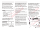
1
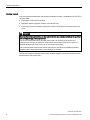
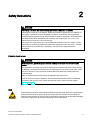
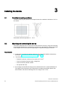
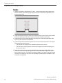
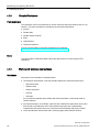
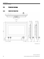
IPC277D 19" INOX PRO
___________________
Preface
1
___________________
Product description
SIMATIC
Industrial PC
IPC277D 19" INOX PRO
Compact Operating Instructions
2
___________________
Safety instructions
3
___________________
Installing the device
Maintaining and repairing the
4
___________________
device
5
___________________
Specifications
A
___________________
Technical support
02/2015
A5E34893346-AA
Legal information
Warning notice system
This manual contains notices you have to observe in order to ensure your personal safety, as well as to prevent
damage to property. The notices referring to your personal safety are highlighted in the manual by a safety alert
symbol, notices referring only to property damage have no safety alert symbol. These notices shown below are
graded according to the degree of danger.
DANGER
indicates that death or severe personal injury will result if proper precautions are not taken.
WARNING
indicates that death or severe personal injury may result if proper precautions are not taken.
CAUTION
indicates that minor personal injury can result if proper precautions are not taken.
NOTICE
indicates that property damage can result if proper precautions are not taken.
If more than one degree of danger is present, the warning notice representing the highest degree of danger will
be used. A notice warning of injury to persons with a safety alert symbol may also include a warning relating to
property damage.
Qualified Personnel
The product/system described in this documentation may be operated only by personnel qualified for the specific
task in accordance with the relevant documentation, in particular its warning notices and safety instructions.
Qualified personnel are those who, based on their training and experience, are capable of identifying risks and
avoiding potential hazards when working with these products/systems.
Proper use of Siemens products
Note the following:
WARNING
Siemens products may only be used for the applications described in the catalog and in the relevant technical
documentation. If products and components from other manufacturers are used, these must be recommended
or approved by Siemens. Proper transport, storage, installation, assembly, commissioning, operation and
maintenance are required to ensure that the products operate safely and without any problems. The permissible
ambient conditions must be complied with. The information in the relevant documentation must be observed.
Trademarks
All names identified by ® are registered trademarks of Siemens AG. The remaining trademarks in this publication
may be trademarks whose use by third parties for their own purposes could violate the rights of the owner.
Disclaimer of Liability
We have reviewed the contents of this publication to ensure consistency with the hardware and software
described. Since variance cannot be precluded entirely, we cannot guarantee full consistency. However, the
information in this publication is reviewed regularly and any necessary corrections are included in subsequent
editions.
Siemens AG
Division Digital Factory
Postfach 48 48
90026 NÜRNBERG
GERMANY
A5E34893346-AA
Ⓟ 02/2015 Subject to change
Copyright © Siemens AG 2015.
All rights reserved
Preface
Validity
This document applies to devices with the designation IPC277D 19" INOX PRO, article
numbers 6AV7484-4AB00-xxxx.
"xxxx" stands for the variant key of the article number.
This document describes the technical differences between the device and the basic device
IPC277D 19" Touch with the article number 6AV7881-5AE00-3DA0 that is installed in the
IPC277D 19" INOX PRO.
The notes contained in this document take precedence over the information contained in the
documentation of the basic device, in the release notes and in the online help.
You can find the documentation of the basic device on the Internet at the following address:
SIMATIC IPC277D documentation
(http://support.automation.siemens.com/WW/view/en/48958258/133300)
Conventions
The term "device" is also used instead of the product designation in this document.
Figures
This document contains figures of the device described. The figures can deviate from the
particularities of the delivered device.
IPC277D 19" INOX PRO
Compact Operating Instructions, 02/2015, A5E34893346-AA
3
Table of contents
Preface ................................................................................................................................................... 3
1
Product description ................................................................................................................................. 5
2
Safety instructions .................................................................................................................................. 9
3
Installing the device ...............................................................................................................................10
4
5
A
3.1
Permitted mounting positions................................................................................................. 10
3.2
Mounting and connecting the device ..................................................................................... 10
Maintaining and repairing the device ......................................................................................................16
4.1
4.1.1
4.1.2
4.1.3
4.1.4
Cleaning the device ............................................................................................................... 16
Cleaning the Device Front ..................................................................................................... 16
Clean screen .......................................................................................................................... 17
Chemical Resistance ............................................................................................................. 18
Working with stainless steel surfaces .................................................................................... 18
4.2
Repair..................................................................................................................................... 19
Specifications ........................................................................................................................................20
5.1
Certificates and approvals ..................................................................................................... 20
5.2
5.2.1
5.2.2
Dimension drawings ............................................................................................................... 22
IPC277D 19" INOX PRO........................................................................................................ 22
Mechanical interface of the device ........................................................................................ 23
5.3
5.3.1
5.3.2
5.3.3
5.3.3.1
5.3.3.2
5.3.3.3
Technical specifications ......................................................................................................... 23
General technical specifications ............................................................................................ 23
Environmental conditions ....................................................................................................... 25
Power supply.......................................................................................................................... 26
Power requirements of additional components...................................................................... 26
Power consumption ............................................................................................................... 26
DC power supply .................................................................................................................... 27
5.4
Pin assignment of the internal terminal strip .......................................................................... 27
Technical support ..................................................................................................................................28
A.1
Service and support ............................................................................................................... 28
IPC277D 19" INOX PRO
4
Compact Operating Instructions, 02/2015, A5E34893346-AA
1
Product description
The following figures show the front and rear views of the IPC277D 19" INOX PRO.
①
②
③
④
Illuminated pushbutton "left" with green LED
Illuminated pushbutton "right" with red LED
Display with touch screen
EMERGENCY OFF button
⑤
⑥
⑦
⑧
Nameplate
Connection compartment
Mechanical interface for fastening
Rear panel
Note
EMERGENCY OFF button
The connections of the EMERGENCY OFF button are wired to pins 1-4 of the terminal strip
in the connection compartment.
The EMERGENCY OFF button is not connected with the installed SIMATIC IPC277D 19".
IPC277D 19" INOX PRO
Compact Operating Instructions, 02/2015, A5E34893346-AA
5
Product description
Features
The housing of the IPC277D 19" INOX PRO contains the standard device
SIMATIC IPC277D 19".
In addition, the IPC277D 19" INOX PRO has the following properties:
• Enclosure material:
INOX stainless steel, material number 1.4301
• Sealing material:
FPM (fluorinated rubber)
• Front membrane:
Polyester-based
• Degree of protection:
IP66K all-round
• Front operator controls: 2 illuminated pushbuttons, 1 EMERGENCY OFF button, wired to
internal terminal strip 1
• Mechanical interface:
1
For stand mounting
For pin assignment of the internal terminal strip, see section
"Pin assignment of the internal terminal strip (Page 27)"
Scope of delivery
● 1 x IPC277D 19" INOX PRO
● 1 x 2-pin connecting terminal for the 24 V DC power supply
● 1 x 20-pin connecting terminal, matching the internal 20-pin terminal strip of the device
● 1 x seal for mechanical interface
Accessories
Mounting kit for stand mounting
A mounting kit is available for stand mounting of the device. Mounting kit contents:
● 1 stainless steel tube with flange: Length 500 mm, outer diameter 48.3 mm, inner
diameter 40 mm.
The mechanical interface of the stainless steel tube with flange fits the mechanical
interface of the device.
● 4 hexagon screws M5×25 made of stainless steel
● 1 flat seal
Article number 6AV7675-1GB00-0AA0
IPC277D 19" INOX PRO
6
Compact Operating Instructions, 02/2015, A5E34893346-AA
Product description
Mounting kit for support arm mounting
A mounting kit is available for support arm mounting of the device. Mounting kit contents:
● 1 stainless steel tube with flange: Length 500 mm, outer diameter 48.3 mm, inner
diameter 40 mm.
The mechanical interface of the stainless steel tube with flange fits the mechanical
interface of the device.
● 1 adapter support arm
● 8 hexagon screws M5×20 made of stainless steel
● 2 flat seals
Article number 6AV7675-1GB10-0AA0
Service pack
The service pack contains:
● 1 spare seal for the connection compartment cover of the device
● 6 screws for the connection compartment cover of the device
● 1 spare seal for the mechanical interface of the device
● 4 screws for fastening the stainless steel tube with flange from a mounting kit to the
mechanical interface of the device
● 1 connecting terminal for the power supply
● 1 terminal block for the terminal strip in the connection compartment
● Documentation
Article number 6AV7675-1JD20-0AA0
Service pack 2, only in combination with the service manual
The service pack 2 contains:
● 1 spare seal for the rear panel of the device
● 4 spare screws for the rear panel of the device
● 1 spare seal for the mechanical interface of the device
● 4 screws for fastening the stainless steel tube with flange from a mounting kit to the
mechanical interface of the device
● 1 connecting terminal for the power supply
● Documentation
Article number 6AV7675-1JD21-0AA0
IPC277D 19" INOX PRO
Compact Operating Instructions, 02/2015, A5E34893346-AA
7
Product description
Service manual
A service manual that describes the following maintenance work is available for the IPC277D
19" INOX PRO:
● Replacing the seal of the rear panel
● Replacing defective operator controls in the device front
● Converting a device for stand mounting into a device for support arm mounting and vice
versa
WARNING
Opening the device and working on the opened device may only be carried out by qualified
and correspondingly trained personnel
The service manual describes, amongst other points, the opening of the device and
working on the wiring or on electronic components in the inside of the device. Injuries or
material damage may result if the work is not carried out correctly.
The work described in the service manual may only be carried out by qualified specialist
personnel who have been trained correspondingly by Siemens.
The service manual is available online under "Product Support" next to this document in the
same branch of the product tree.
IPC277D 19" INOX PRO
8
Compact Operating Instructions, 02/2015, A5E34893346-AA
Safety instructions
2
WARNING
Performing a function test when installing the device in machines or systems
Following the results of a risk analysis, additional protection equipment on the machine or
the system is necessary to avoid endangering persons. In particular, the programming,
parameter assignment and wiring of the inserted I/O must be executed in accordance with
the safety performance identified by the necessary risk analysis (SIL, PL or Cat.). The
intended use of the device has to be ensured.
The proper use of the device has to be verified with a function test on the system. These
tests help you to identify programming, parameter assignment and wiring errors. The test
results have to be recorded and, if necessary, entered into the safety verification
documents.
Defective touch screen
WARNING
Risk of explosion, personal injury or material damage in the case of a defective touch
screen
The application of excessive force to the device front can destroy the device touch screen,
for example, piercing the front membrane or breaking the touch screen carrier plate. There
is a risk of explosion, injury and food contamination with additional consequential and
health damage.
Make sure that excessive force cannot be applied to the device front.
If the device touch screen is defective, decommission the affected machine immediately
and replace the device at once. When replacing the device, please note the chapter
"Repair (Page 19)".
ESD
Electrostatically sensitive components include almost all electrical, electronic, optoelectronic
and electromechanical components. These components are sensitive to overvoltage for
technical reasons and their function may be impaired or destroyed by electrostatic discharge.
Observe the regulations governing the handling of ESD components.
IPC277D 19" INOX PRO
Compact Operating Instructions, 02/2015, A5E34893346-AA
9
3
Installing the device
3.1
Permitted mounting positions
The device may only be operated in landscape format with a maximum inclination of ±30° to
the vertical.
Permissible ambient temperature: 0 ... 45 °C
3.2
Mounting and connecting the device
This section describes how to mount and connect the device correctly, using stand mounting
as an example. Mounting on a support arm is carried out in the same way. All the work steps
in this chapter have to be carried out sequentially for complete mounting of the device.
Requirements
● A stand with a mechanical interface suitable for the mechanical interface of the device;
see section "Mechanical interface of the device (Page 23)".
●
The following lines are routed through the stand:
– Protective conductor, minimum cross-section of 2.5 mm2
– Lines for the external power supply, voltage-free
– Lines for the front operator controls
– All required data lines
● Four hexagon screws M5 according to screw standard ISO 4017, material X5CrNi18-10
The length of the screws have to be dimensioned so that the penetration depth of the
screw thread in the device-side flange lies in the range of 6 to 10 mm.
IPC277D 19" INOX PRO
10
Compact Operating Instructions, 02/2015, A5E34893346-AA
Installing the device
3.2 Mounting and connecting the device
Opening the connection compartment and installing the device
Note
The device is fastened to a stand or a support arm via the mechanical interface with four
screws.
Siemens AG assumes no liability for the consequences of a faulty installation.
WARNING
The device must be mounted securely
Inadequately dimensioned fastening material may cause the device to fall down. Serious
bodily injury may result.
Make sure that fasteners are adequately dimensioned during installation of the device.
Make sure to consider the weight of the device and the forces acting on the device when
dimensioning the fasteners. This applies in particular to dynamic load of the device.
Observe any further statutory specifications applying at the location of use of the device
and further applicable regulations with regard to the fastening of the device.
NOTICE
Placing the device on its front can damage operator controls
If you place the device on its front before or during the installation, the operator controls on
the front can be damaged.
Place the device on a soft and elevated surface so that the front operator controls do not
contact the working area and are not damaged.
IPC277D 19" INOX PRO
Compact Operating Instructions, 02/2015, A5E34893346-AA
11
Installing the device
3.2 Mounting and connecting the device
Procedure
1. Open the connection compartment. To do so, remove the 6 screws on the device rear
that are marked in the following figure and remove the connection compartment cover
and associated seal.
2. Place the supplied seal for the mechanical interface with its smooth side onto the stand.
Center the openings of the seal and of the mechanical interface of the stand.
3. Route the lines from the stand through the opening of the mechanical interface of the
device into the connection compartment.
4. Place the mechanical interface of the device onto the mechanical interface of the stand.
Take the following into account:
– The seal has to lie exactly in the mechanical interface of the device.
– The lines must not be squeezed. Hold the lines slightly tensioned while placing the
device on the stand.
5. Fasten the device to the mechanical interface of the stand using the four M5 screws.
Insert the screws from below through the mechanical interface and tighten the screws
with a torque of 3.5 Nm. The degree of protection IP66K is only ensured with this torque.
The device is mounted on the stand. The following steps describe the installation in the
connection compartment.
IPC277D 19" INOX PRO
12
Compact Operating Instructions, 02/2015, A5E34893346-AA
Installing the device
3.2 Mounting and connecting the device
6. The following figure shows the position of the interfaces, the on-off switch and the battery
compartment.
Switch the device off using the on-off switch ⑧.
①
②
CompactFlash interface
③
④
⑤
COM port, Sub-D connector
USB 2.0 ports. A maximum of 2 USB ports may
be operated simultaneously in high-current mode.
Ethernet interfaces LAN1 and LAN2
⑥
⑦
Connection for protective conductor
⑧
⑨
On/off switch
Connection for the 24 V DC power
supply
Internal terminal strip, 20-pin
Battery compartment
Note
The interfaces are rotated by 180° in comparison to the standard device.
Correspondingly, the memory card and lines are to be connected or plugged rotated by
180°.
IPC277D 19" INOX PRO
Compact Operating Instructions, 02/2015, A5E34893346-AA
13
Installing the device
3.2 Mounting and connecting the device
Connecting the device and closing the connection compartment
Important notes on connecting
The protective conductor connection is needed to protect the device and helps ensure that
interference signals generated by power lines, signal lines or lines to I/O devices are safely
discharged to earth.
The protective conductor connection on the device must be connected to the protective
conductor of the control cabinet or system in which the device is installed.
WARNING
Electric shock and fire hazard when protective conductor is not connected
High voltage may be present in a defective device, which can cause fire or an electric
shock if touched. Death and serious bodily injury can result.
• Connect the device to the protective conductor before you put it into operation.
• Never operate the device without protective conductor.
• If a device is defective, remove it from operation without delay and label it accordingly.
WARNING
Risk of fire and electric shock
The on/off switch does not isolate the device from the power supply. Risk of electric shock if
the device is opened incorrectly or defective. There is also a risk of fire if the device or
connecting lines are damaged.
You should therefore protect the device as follows:
• Always pull out the power plug when you are not using the device or if the device is
defective. The power plug must be freely accessible.
• Connect the device to a protective conductor as instructed (see "Connecting the
protective conductor").
• Use a central isolating switch in the case of cabinet installation.
WARNING
Electric shock and fire hazard with unsuitable power supply
Voltages that exceed an extra-low voltage can cause electric shock or fire. Death or serious
bodily injury can result.
• Always wire the device to a 24 V DC power supply that is compliant with SELV
requirements in accordance with IEC/UL/EN/DIN EN 60950-1.
• A current source in accordance with NEC Class 2 is required in order to fulfill the
requirements according to UL 60950-1 and UL 508.
• In all other cases according to IEC/EN/DIN EN 60950-1, either a current source of
limited output (LPS = Low Power Source), or a line-side fuse or a line-side circuit
breaker is necessary. Current must be limited to 4.16 A. This requires a max. 4 A fuse.
IPC277D 19" INOX PRO
14
Compact Operating Instructions, 02/2015, A5E34893346-AA
Installing the device
3.2 Mounting and connecting the device
Procedure
1. Connect the protective conductor to the protective conductor connection ⑥ in
accordance with the SIMATIC IPC277D operating instructions. The protective conductor
connection is identified by the following symbol:
The minimum cross-section of the protective conductor is 2.5 mm2.
The protective conductor connection is needed to protect the device and helps ensure
that interference signals generated by power lines, signal lines or lines to I/O devices are
safely discharged to earth.
2. Connect the lines for the power supply in accordance with the SIMATIC IPC277D
operating instructions via the associated connecting terminal to the connection for the
power supply ⑦.
3. If you use a memory card, insert the memory card.
4. Connect the connectors of the data lines to the corresponding interface.
5. Secure the data lines with cable ties to the fastening elements in the connection
compartment that are marked in the following figure.
6. Switch the device on using the on/off switch ⑧.
7. Place the seal of the connection compartment cover around the connection compartment.
Ensure that the latches of the seal lie in the associated notches and that the seal lies
flush on the device rear panel.
8. Fasten the connection compartment cover with 6 screws. Tighten the screws using a
torque of 3.5 Nm.
IPC277D 19" INOX PRO
Compact Operating Instructions, 02/2015, A5E34893346-AA
15
4
Maintaining and repairing the device
4.1
Cleaning the device
4.1.1
Cleaning the Device Front
The device is designed for low-maintenance operation. You should still clean the device front
regularly, however.
CAUTION
Unwanted reactions when cleaning the device
You risk unintentional actuation of operator controls if you clean the device while it is
switched on.
You may possibly trigger unwanted actions of the device or controller that are liable to
cause personal injury or damage to the machinery.
Always switch off the device before you clean it.
Cleaning Agents
NOTICE
Damage to the device due to impermissible cleaning agents
Impermissible and unsuitable cleaning agents may cause damage to the HMI device.
Use dish soap or foaming screen cleaner only as cleaning agents.
Do not use aggressive solvents or scouring powder.
Cleaning the Device Front
1. Switch off the device.
2. Dampen the cleaning cloth.
3. Spray the cleaning agent on the cloth and not directly on the device.
4. Clean the device with the cleaning cloth.
IPC277D 19" INOX PRO
16
Compact Operating Instructions, 02/2015, A5E34893346-AA
Maintaining and repairing the device
4.1 Cleaning the device
Note
Cleaning methods
In addition to the specifications in this section, the following applies for cleaning the device:
Permitted: Cleaning with strong jet water under increased pressure in accordance with
ISO 20653:2013, specifications on "IP66K".
Not permitted:
• Do not clean the HMI device using aggressive cleaners or detergents, greasing or
abrasive detergents, acids or caustic solutions, leather, scratching or rough rags and
equipment.
For further information, refer to the section "Chemical resistance".
• Do not clean the HMI device with chlorine or chloride, for example, active chlorine, laser
or ultrasonic equipment or dry ice.
• You damage the operating front if you clean the HMI device with high pressure
equipment. Do not disinfect the device thermally, for example, using hot steam
equipment, because this would damage the operating front, particularly the touch sensor
system.
4.1.2
Clean screen
If you use the WinCC RT Advanced software in connection with the device, you can clean
the touch screen of the device while it is switched on and the project running. An operating
element must be available in the project that can be used to call the "clean" screen. Once
the clean screen is activated, touch screen operation is locked for a configured period of
time. The time the touch screen is locked can be set between 5 and 30 seconds. The time
remaining for the lockout is indicated by a progress bar.
Note
Unintentional responses
When cleaning the touch screen, an unintentional response in the controller can be triggered
by touching keys.
Always open the clean screen or switch off the device before you clean the touch screen
while the system is running.
Cannot be operated when the clean screen is active
When the clean screen is active, operations on the device are not possible.
Wait for the period of the clean screen to lapse. Then you can operate the system again with
the device.
IPC277D 19" INOX PRO
Compact Operating Instructions, 02/2015, A5E34893346-AA
17
Maintaining and repairing the device
4.1 Cleaning the device
4.1.3
Chemical Resistance
Front membrane
The resistance of the front membrane to various chemicals has been tested to DIN 42 115,
section 2. The front membrane is resistant to the chemicals listed below:
● Alcohol
● Diluted acids
● Diluted caustic solutions
● Ester
● Hydrocarbons
● Household cleaners
You can find information of chemical resistance on the Internet
(http://support.automation.siemens.com/WW/view/en/39718396).
Seals
The seals made of FPM (fluorinated rubber) are approved for food according to FDA
regulations.
4.1.4
Working with stainless steel surfaces
Resistance
Information on the resistance of stainless steel:
● The stainless steel surface is not fully resistant against the chemicals listed below:
– Hydrochloric acid
– Sulphuric acid
– Sodium hydroxide
– Chlorine
– Chlorides
Do not clean the stainless steel surface with these chemicals or with similar acids or
caustic solutions.
● Acid steam develops, for example, when tiles are cleaned with hydrochloric acid, and is
also harmful to the stainless steel. If the stainless steel parts are unintentionally
contaminated with hydrochloric acid, rinse these off immediately with plenty of water.
● Clean the stainless steel surface with a cleansing agent without active chlorine.
IPC277D 19" INOX PRO
18
Compact Operating Instructions, 02/2015, A5E34893346-AA
Maintaining and repairing the device
4.2 Repair
Cleaning guidelines
Further information on stainless steel surfaces:
● The surface should be properly ventilated.
● Keep the surface clean. Remove cleaners and food residue immediately. Always avoid
the return of food stuff splashes to the production process.
● If mechanical cleaning is necessary, do not use cleaning equipment made of metal.
– Use brushes made of plastic or natural materials, or a microfiber pad.
– Use plenty of water to clean the surface.
– Make sure that the cleansing agent is completely removed without any residue.
● Make sure surface is not damaged: Do not damage the device during operation, or by
cleaning or repairing it using hard tools, in particular tools made of corrodible materials.
● Make sure that the surface does not come into contact with rusted parts.
This includes water pipes, filings, residue from wire brushes or steel wool. These, as well
as rust films have a corrosive effect on parts made of stainless steel.
– Remove any stains or rust immediately.
– Remove new rust spots with a mild abrasive detergent in order to prevent any further
corrosion.
– Rinse the part thoroughly after you cleaned it.
4.2
Repair
In case of repair, the HMI device must be shipped to the Return Center in Fürth. Repairs
may only be carried out at the Return Center in Fürth.
The device described in this document is covered by the conditions of repair and return of
equipment, as follows:
1. You return the defective device to the returned goods center. The address is:
Siemens AG
Digital Factory
Retouren-Center
Siemensstr. 2
D-90766 Fürth
2. After it has been repaired, the device is returned to you. A new device will not be supplied
in exchange.
Depending on the work necessary to repair the device, the Center may decide to give you a
credit note. In this case, it is your responsibility to order a new device.
For additional information, refer to the Internet at Spare parts and repairs
(http://support.automation.siemens.com/WW/view/en/16611927).
IPC277D 19" INOX PRO
Compact Operating Instructions, 02/2015, A5E34893346-AA
19
5
Specifications
5.1
Certificates and approvals
Note
This section lists the certificates and approvals possible for the device.
Only those approvals specified on the rear of your device apply to your device.
A copy of the certificates can be requested from the following address:
Siemens AG
Digital Factory
Factory Automation
DF FA SE R&D
Breslauer Str. 5
DE-90766 Fürth
DIN ISO 9001 certificate
The Siemens quality management system for all production processes (development,
production and sales) meets the requirements of DIN ISO 9001:2000.
This has been certified by DQS (the German society for the certification of quality
management systems).
Certificate registration no. DE-000656 QM08
Software license agreements
If the device is supplied with preinstalled software, you must observe the corresponding
license agreements.
UL approval
Underwriters Laboratories (UL) to UL 508 standard and Canadian National Standard
CAN/CSA-C22.2 No. 142 (IND.CONT.EQ)
IPC277D 19" INOX PRO
20
Compact Operating Instructions, 02/2015, A5E34893346-AA
Specifications
5.1 Certificates and approvals
FM Approval
Factory Mutual Research (FM) conforming to
● Approval Standard Class Number 3611, 3600, 3810, ANSI/ISA 61010-1
● CSA C22.2 No. 213
● CSA C22.2 No. 1010.1
Approved for use in
● Class I, Division 2, Group A, B, C, D T4
● Class I, Zone 2, Group IIC T4
ATEX approval
The following approvals apply to the device in accordance with
● EN 60079-15 (Electrical apparatus for potentially explosive atmospheres; Type of
protection "n") and
● EN 60079-0 (Electrical apparatus for potentially explosive gas atmospheres - Part 0:
General Requirements)
valid:
II 3 G
Ex nA IIC T4 Gc
Notes on CE marking
This product meets the requirements and safety objectives of the EMC directive
2004/108/EEC "Electromagnetic Compatibility", and is designed for operation in the following
fields of application according to this CE marking:
Field of application
Requirement for emissions
Requirement for interference immunity
Industrial area
EN 61000-6-4:2007 +A1:2011
EN 61000-6-2:2005
IPC277D 19" INOX PRO
Compact Operating Instructions, 02/2015, A5E34893346-AA
21
Specifications
5.2 Dimension drawings
5.2
Dimension drawings
5.2.1
IPC277D 19" INOX PRO
IPC277D 19" INOX PRO
22
Compact Operating Instructions, 02/2015, A5E34893346-AA
Specifications
5.3 Technical specifications
5.2.2
Mechanical interface of the device
5.3
Technical specifications
5.3.1
General technical specifications
1
2
Weight
Approx. 15 kg
Power supply 1
24V DC (19.2 to 28.8 V)
Short-term voltage interruption in
accordance with Namur
Min. 20 ms (DC), max. 10 events per hour; min. 1 s recovery time
Rated power consumption (DC):
Continuous current 2 A
Degree of protection
IP66k all-round 2 according to ISO 20653:2013
Quality assurance
In accordance with ISO 9001
The generation of the supply voltage with the line-side power supply must be realized as safety
extra-low voltage with safe electrical isolation, isolated as SELV according to
IEC/UL/EN/DIN-EN 60950-1 and LPS/NEC Class 2.
When all the covers are closed and all the connecting lines have been connected properly with the
device
IPC277D 19" INOX PRO
Compact Operating Instructions, 02/2015, A5E34893346-AA
23
Specifications
5.3 Technical specifications
Electromagnetic compatibility
Emission standard
EN 61000-6-4; CISPR 22:2010 Class A; FCC Class A
Immunity with regard
to conducted
interference on the
supply lines
± 2 kV in accordance with IEC 61000-4-4; burst
± 1 kV in accordance with IEC 61000-4-5; symmetrical surge
± 2 kV in accordance with IEC 61000-4-5; asymmetrical surge
Noise immunity on
signal lines
± 2 kV in accordance with IEC 61000-4-4; burst; length > 3 m
± 2 kV in accordance with IEC 61000-4-5; symmetrical surge, length > 30 m
Immunity to
electrostatic discharge
± 6 kV contact discharge in accordance with IEC 61000-4-2
± 8 kV air discharge in accordance with IEC 61000-4-2
Immunity to RF
interference
10 V/m, 80 to 2000 MHz
80% AM according to IEC 61000-4-3
3 V/m, 2 to 2.7 GHz
10 V, 9 kHz to 80 MHz according to IEC 61000-4-6
Immunity to magnetic
fields
100 A/m, 50/60 Hz according to IEC 61000-4-8
Processor
Intel Atom 1.3 GHz
Main memory
DDR2, 2 GB, memory cannot be exchanged.
Backup memory
512 KB MRAM, of which 128 KB can be backed up at full load in the buffer
time of the power supply
Main circuit board
Drive, memory medium
1
CompactFlash memory card
8 GB
Floppy and CD-ROM drive
External, can be connected via USB port 1
USB stick
External, can be connected via USB port
Only to USB port of the device, not via USB hub
Graphics
Display, resolution
19" diagonal with backlighting, resolution 1366 x 768 pixels
Touch controller
Resistive Semtech controller ELO CTR-2216SU-AT-CHP-00
Touch screen analog resistive
Touch force with test pen; 2 mm diameter: 5 N
Backlighting (MTBF)
LED
Half brightness life time, typical
min. 50000 h at 50 °C, 50% brightness
Pixel error class in accordance with
ISO 9241-307
I
IPC277D 19" INOX PRO
24
Compact Operating Instructions, 02/2015, A5E34893346-AA
Specifications
5.3 Technical specifications
Interfaces
COM 1
RS232, max. 115 kbps, sub-D connector, 9-pin
USB
3 × USB 2.0, a maximum of 2 can be operated in high-current
mode at the same time
LAN interface X1 P1, RJ45 1
Intel Platform Controller Hub EG20T Gigabit Ethernet;
10, 100, 1000 Mbps
LAN interface X2 P1, RJ45 1
Intel 82574L Gigabit Ethernet controller;
10, 100, 1000 Mbps, teaming is supported 2
Keyboard, mouse
Connection via USB port
For unique labeling, the LAN interfaces are numbered on the enclosure. The numbering by the
operating system can differ.
Teaming can be set and initiated in the configuration interface. In teaming operation, jumbo
frames, e.g. for the camera application, are not supported.
1
2
5.3.2
Environmental conditions
Climatic ambient conditions
Temperature, tested in accordance with
IEC 60068-2-1, IEC 60068-2-2
•
Temperature gradient in operation
•
Max. 10 °C/h, no condensation
•
Ambient temperature in operation
•
0 ... 45 °C
•
Temperature during storage/transport
•
-20 to +60 °C
•
Storage/transport, gradient
•
Max. 20 °C/h, no condensation
Relative humidity, tested in accordance with
IEC 60068-2-78, IEC 60068-2-30
•
Operation
•
5 … 85 % at 30 °C, no condensation
•
Storage/transport
•
5 … 95 % at 25/55 °C, no condensation
Air pressure, in accordance
with IEC 60068-2-13
•
Operation
•
1080 to 795 hPa, corresponds to an elevation of -1000 to 2000 m
•
Storage/transport
•
1080 to 660 hPa, corresponds to an elevation of -1000 to 3500 m
IPC277D 19" INOX PRO
Compact Operating Instructions, 02/2015, A5E34893346-AA
25
Specifications
5.3 Technical specifications
Mechanical ambient conditions
Vibration, tested according to IEC 60068-2-6
•
Operation
•
10 to 58 Hz: 0.15 mm
58 to 500 Hz: 10 m/s2, 10 cycles
•
Storage/transport
•
5 to 8.5 Hz: 7 mm
8.5 to 500 Hz: 10 m/s2
Shock resistance, tested in accordance with
IEC 60068-2-27, IEC 60068-2-29
•
Operation
•
150 m/s2, 11 ms, 100 shocks per axis
•
Storage/transport
•
250 m/s2, 6 ms, 1000 shocks per axis
5.3.3
Power supply
5.3.3.1
Power requirements of additional components
Maximum permitted current consumption at the USB ports
5.3.3.2
Auxiliary components
Maximum permitted power consumption,
voltage +5 V
Max. total power
USB device
High current
500 mA
6W
Low current
100 mA
Power consumption
Device
Typical power consumption (at a rated voltage of 24 V)
Basic device ATOM 1.3 GHz /
2 GB RAM with display
36 W
Maximum USB extension
Max. 6 W
IPC277D 19" INOX PRO
26
Compact Operating Instructions, 02/2015, A5E34893346-AA
Specifications
5.4 Pin assignment of the internal terminal strip
5.3.3.3
DC power supply
Input voltage
Power consumption
1
24 VDC (19.2 to 28.8 VDC)
1
Max. 72 W
Power failure buffering
Hold-up time > 15 ms
(after > 5 ms, DC_FAIL becomes active)
Maximum continuous output power 1
60 W
The performance specifications apply to the power supply component, but not to the device.
Note
Inrush current
The device needs an inrush current of at least 4.5 A for 25 ms.
The peak value of the inrush current depends on the input voltage and the impedance of the
24 V source; peak currents in excess of 4.5 A are possible. This will not have a negative
impact on device functionality.
5.4
Pin assignment of the internal terminal strip
The following figure shows the pin assignment of the internal 20-pin terminal strip.
Pins 1 to 12 are wired with the front operator controls.
Pins 13 to 20 are not assigned.
IPC277D 19" INOX PRO
Compact Operating Instructions, 02/2015, A5E34893346-AA
27
A
Technical support
A.1
Service and support
You can find additional information and support for the products described on the Internet at
the following addresses:
● Technical support (http://www.siemens.de/automation/csi_en_WW)
● Support request form (http://www.siemens.com/automation/support-request)
● After Sales Information System SIMATIC IPC/PG (http://www.siemens.com/asis)
● SIMATIC Documentation Collection (http://www.siemens.com/simatic-tech-doku-portal)
● Your local representative
(http://www.automation.siemens.com/mcms/aspa-db/en/Pages/default.aspx)
● Training center (http://sitrain.automation.siemens.com/sitrainworld/?AppLang=en)
● Industry Mall (https://mall.industry.siemens.com)
When contacting your local representative or Technical Support, please have the following
information at hand:
● MLFB of the device
● BIOS version for industrial PC or image version of the device
● Other installed hardware
● Other installed software
Tools & downloads
Please check regularly if updates and hotfixes are available for download to your device. The
download area is available on the Internet at the following link:
After Sales Information System SIMATIC IPC/PG (http://www.siemens.com/asis)
IPC277D 19" INOX PRO
28
Compact Operating Instructions, 02/2015, A5E34893346-AA