1
SPARC Enterprise
M3000/M4000/M5000/M8000/M9000 Servers
Administration Guide
Part No.: E21618-02
Manual Code: C120-E331-13EN
June 2012
Copyright © 2007, 2012, Oracle and/or its affiliates. All rights reserved.
Fujitsu Limited provided technical input and review on portions of this material.
Oracle and/or its affiliates and Fujitsu Limited each own or control intellectual property rights relating to products and technology described in this
document, and such products, technology and this document are protected by copyright laws, patents, and other intellectual property laws and
international treaties.
This document and the product and technology to which it pertains are distributed under licenses restricting their use, copying, distribution, and
decompilation. No part of such product or technology, or of this document, may be reproduced in any form by any means without prior written
authorization of Oracle and/or its affiliates and Fujitsu Limited, and their applicable licensors, if any. The furnishings of this document to you does not
give you any rights or licenses, express or implied, with respect to the product or technology to which it pertains, and this document does not contain or
represent any commitment of any kind on the part of Oracle or Fujitsu Limited, or any affiliate of either of them.
This document and the product and technology described in this document may incorporate third-party intellectual property copyrighted by and/or
licensed from the suppliers to Oracle and/or its affiliates and Fujitsu Limited, including software and font technology.
Per the terms of the GPL or LGPL, a copy of the source code governed by the GPL or LGPL, as applicable, is available upon request by the End User. Please
contact Oracle and/or its affiliates or Fujitsu Limited.
This distribution may include materials developed by third parties.
Parts of the product may be derived from Berkeley BSD systems, licensed from the University of California. UNIX is a registered trademark in the U.S. and
in other countries, exclusively licensed through X/Open Company, Ltd.
Oracle and Java are registered trademarks of Oracle and/or its affiliates. Fujitsu and the Fujitsu logo are registered trademarks of Fujitsu Limited.
All SPARC trademarks are used under license and are registered trademarks of SPARC International, Inc. in the U.S. and other countries. Products bearing
SPARC trademarks are based upon architectures developed by Oracle and/or its affiliates. SPARC64 is a trademark of SPARC International, Inc., used
under license by Fujitsu Microelectronics, Inc. and Fujitsu Limited. Other names may be trademarks of their respective owners.
United States Government Rights - Commercial use. U.S. Government users are subject to the standard government user license agreements of Oracle
and/or its affiliates and Fujitsu Limited and the applicable provisions of the FAR and its supplements.
Disclaimer: The only warranties granted by Oracle and Fujitsu Limited, and/or any affiliate of either of them in connection with this document or any
product or technology described herein are those expressly set forth in the license agreement pursuant to which the product or technology is provided.
EXCEPT AS EXPRESSLY SET FORTH IN SUCH AGREEMENT, ORACLE OR FUJITSU LIMITED, AND/OR THEIR AFFILIATES MAKE NO
REPRESENTATIONS OR WARRANTIES OF ANY KIND (EXPRESS OR IMPLIED) REGARDING SUCH PRODUCT OR TECHNOLOGY OR THIS
DOCUMENT, WHICH ARE ALL PROVIDED AS IS, AND ALL EXPRESS OR IMPLIED CONDITIONS, REPRESENTATIONS AND WARRANTIES,
INCLUDING WITHOUT LIMITATION ANY IMPLIED WARRANTY OF MERCHANTABILITY, FITNESS FOR A PARTICULAR PURPOSE OR NONINFRINGEMENT, ARE DISCLAIMED, EXCEPT TO THE EXTENT THAT SUCH DISCLAIMERS ARE HELD TO BE LEGALLY INVALID. Unless
otherwise expressly set forth in such agreement, to the extent allowed by applicable law, in no event shall Oracle or Fujitsu Limited, and/or any of their
affiliates have any liability to any third party under any legal theory for any loss of revenues or profits, loss of use or data, or business interruptions, or for
any indirect, special, incidental or consequential damages, even if advised of the possibility of such damages.
DOCUMENTATION IS PROVIDED “AS IS” AND ALL EXPRESS OR IMPLIED CONDITIONS, REPRESENTATIONS AND WARRANTIES,
INCLUDING ANY IMPLIED WARRANTY OF MERCHANTABILITY, FITNESS FOR A PARTICULAR PURPOSE OR NON-INFRINGEMENT, ARE
DISCLAIMED, EXCEPT TO THE EXTENT THAT SUCH DISCLAIMERS ARE HELD TO BE LEGALLY INVALID.
Please
Recycle
Copyright © 2007, 2012, Oracle et/ou ses sociétés affiliées. Tous droits réservés.
Fujitsu Limited a fourni et vérifié des données techniques de certaines parties de ce composant.
Oracle et/ou ses sociétés affiliées et Fujitsu Limited détiennent et contrôlent chacune des droits de propriété intellectuelle relatifs aux produits et
technologies décrits dans ce document. De même, ces produits, technologies et ce document sont protégés par des lois sur le copyright, des brevets,
d’autres lois sur la propriété intellectuelle et des traités internationaux.
Ce document, le produit et les technologies afférents sont exclusivement distribués avec des licences qui en restreignent l’utilisation, la copie, la
distribution et la décompilation. Aucune partie de ce produit, de ces technologies ou de ce document ne peut être reproduite sous quelque forme que ce
soit, par quelque moyen que ce soit, sans l’autorisation écrite préalable d’Oracle et/ou ses sociétés affiliées et de Fujitsu Limited, et de leurs éventuels
bailleurs de licence. Ce document, bien qu’il vous ait été fourni, ne vous confère aucun droit et aucune licence, expresses ou tacites, concernant le produit
ou la technologie auxquels il se rapporte. Par ailleurs, il ne contient ni ne représente aucun engagement, de quelque type que ce soit, de la part d’Oracle ou
de Fujitsu Limited, ou des sociétés affiliées de l’une ou l’autre entité.
Ce document, ainsi que les produits et technologies qu’il décrit, peuvent inclure des droits de propriété intellectuelle de parties tierces protégés par
copyright et/ou cédés sous licence par des fournisseurs à Oracle et/ou ses sociétés affiliées et Fujitsu Limited, y compris des logiciels et des technologies
relatives aux polices de caractères.
Conformément aux conditions de la licence GPL ou LGPL, une copie du code source régi par la licence GPL ou LGPL, selon le cas, est disponible sur
demande par l’Utilisateur final. Veuillez contacter Oracle et/ou ses sociétés affiliées ou Fujitsu Limited.
Cette distribution peut comprendre des composants développés par des parties tierces.
Des parties de ce produit peuvent être dérivées des systèmes Berkeley BSD, distribués sous licence par l’Université de Californie. UNIX est une marque
déposée aux États-Unis et dans d’autres pays, distribuée exclusivement sous licence par X/Open Company, Ltd.
Oracle et Java sont des marques déposées d’Oracle Corporation et/ou de ses sociétés affiliées. Fujitsu et le logo Fujitsu sont des marques déposées de
Fujitsu Limited.
Toutes les marques SPARC sont utilisées sous licence et sont des marques déposées de SPARC International, Inc., aux États-Unis et dans d’autres pays. Les
produits portant la marque SPARC reposent sur des architectures développées par Oracle et/ou ses sociétés affiliées. SPARC64 est une marque de SPARC
International, Inc., utilisée sous licence par Fujitsu Microelectronics, Inc. et Fujitsu Limited. Tout autre nom mentionné peut correspondre à des marques
appartenant à d’autres propriétaires.
United States Government Rights - Commercial use. U.S. Government users are subject to the standard government user license agreements of Oracle
and/or its affiliates and Fujitsu Limited and the applicable provisions of the FAR and its supplements.
Avis de non-responsabilité : les seules garanties octroyées par Oracle et Fujitsu Limited et/ou toute société affiliée de l’une ou l’autre entité en rapport
avec ce document ou tout produit ou toute technologie décrits dans les présentes correspondent aux garanties expressément stipulées dans le contrat de
licence régissant le produit ou la technologie fournis. SAUF MENTION CONTRAIRE EXPRESSÉMENT STIPULÉE DANS CE CONTRAT, ORACLE OU
FUJITSU LIMITED ET LES SOCIÉTÉS AFFILIÉES À L’UNE OU L’AUTRE ENTITÉ REJETTENT TOUTE REPRÉSENTATION OU TOUTE GARANTIE,
QUELLE QU’EN SOIT LA NATURE (EXPRESSE OU IMPLICITE) CONCERNANT CE PRODUIT, CETTE TECHNOLOGIE OU CE DOCUMENT,
LESQUELS SONT FOURNIS EN L’ÉTAT. EN OUTRE, TOUTES LES CONDITIONS, REPRÉSENTATIONS ET GARANTIES EXPRESSES OU TACITES, Y
COMPRIS NOTAMMENT TOUTE GARANTIE IMPLICITE RELATIVE À LA QUALITÉ MARCHANDE, À L’APTITUDE À UNE UTILISATION
PARTICULIÈRE OU À L’ABSENCE DE CONTREFAÇON, SONT EXCLUES, DANS LA MESURE AUTORISÉE PAR LA LOI APPLICABLE. Sauf mention
contraire expressément stipulée dans ce contrat, dans la mesure autorisée par la loi applicable, en aucun cas Oracle ou Fujitsu Limited et/ou l’une ou
l’autre de leurs sociétés affiliées ne sauraient être tenues responsables envers une quelconque partie tierce, sous quelque théorie juridique que ce soit, de
tout manque à gagner ou de perte de profit, de problèmes d’utilisation ou de perte de données, ou d’interruptions d’activités, ou de tout dommage
indirect, spécial, secondaire ou consécutif, même si ces entités ont été préalablement informées d’une telle éventualité.
LA DOCUMENTATION EST FOURNIE « EN L’ÉTAT » ET TOUTE AUTRE CONDITION, DÉCLARATION ET GARANTIE, EXPRESSE OU TACITE, EST
FORMELLEMENT EXCLUE, DANS LA MESURE AUTORISÉE PAR LA LOI EN VIGUEUR, Y COMPRIS NOTAMMENT TOUTE GARANTIE
IMPLICITE RELATIVE À LA QUALITÉ MARCHANDE, À L’APTITUDE À UNE UTILISATION PARTICULIÈRE OU À L’ABSENCE DE
CONTREFAÇON.
Contents
Preface
1.
xiii
Introduction to Server Software and Configuration
XSCF Firmware
2
Oracle Solaris OS Software
Software Services
2
3
Preparing for System Configuration
Information Needed
Related Information
Access Control
5
5
Initial Configuration Tasks
2.
5
6
7
About Access Control
7
Logging in to the System
8
Lockout Period Between Login Attempts
XSCF User Accounts
XSCF Passwords
Privileges
1
8
9
9
10
XSCF Firmware Update
11
Saving and Restoring XSCF Configuration Information
12
v
XSCF Shell Procedures for Access Control
▼
To Log in Initially to the XSCF Console
13
▼
To Configure an XSCF Password Policy
15
▼
To Add an XSCF User Account
▼
To Create a Password for an XSCF User
▼
To Assign Privileges to an XSCF User
▼
To Display the Version of Installed Firmware
Related Information
3.
12
16
16
17
17
18
System Configuration
19
About System Services
19
DSCP Network Between a Service Processor and a Domain
XSCF Network Interfaces
Domain Name Service
LDAP Service
21
23
23
Active Directory and LDAP/SSL
25
Time Synchronization and NTP Service
SNMP Service
27
Additional Services
28
HTTPS Service
28
Telnet Service
28
SMTP Service
29
SSH Service
25
29
Altitude Setting
29
XSCF Shell Procedures for System Configuration
vi
29
▼
To Configure the DSCP Network
▼
To Display DSCP Network Configuration
▼
To Configure the XSCF Network Interfaces
▼
To Configure the XSCF Network Route Information
30
SPARC Enterprise Mx000 Servers Administration Guide • June 2012
31
32
33
20
▼
To Set Or Reset the XSCF Network
▼
To Display XSCF Network Configuration
▼
To Set the Service Processor Host Name and DNS Domain Name
▼
To Set the Service Processor’s DNS Name Server
▼
To Enable or Disable Use of an LDAP Server for Authentication and
Privilege Lookup 36
▼
To Configure the XSCF as an LDAP Client
▼
To Configure the XSCF as an NTP Client
37
▼
To Configure the XSCF as an NTP Server
37
▼
To Display the NTP Configuration
▼
To Set the Timezone, Daylight Saving Time, Date, and Time Locally on the
Service Processor 38
▼
To Create a USM User Known to the SNMP Agent
39
▼
To Display USM Information for the SNMP Agent
40
▼
To Create a VACM Group
▼
To Create a VACM View
▼
To Give a VACM Group Access to a VACM View
▼
To Display VACM Information for the SNMP Agent
▼
To Configure the SNMP Agent to Send Version 3 Traps to Hosts
▼
To Enable the SNMP Agent
▼
To Display SNMP Agent Configuration
▼
To Enable or Disable the Service Processor HTTPS Service
▼
To Enable or Disable the Service Processor Telnet Service
▼
To Configure the Service Processor SMTP Service
▼
To Enable or Disable the Service Processor SSH Service
▼
To Generate a Host Public Key for SSH Service
▼
To Set the Altitude on the Service Processor
Related Information
4.
34
34
35
35
36
38
40
41
41
41
42
43
43
44
45
45
45
46
46
47
Domain Configuration
49
Contents
vii
About Domains
49
Domains and System Boards
50
SPARC64 VII+, SPARC64 VII, and SPARC64 VI Processors and CPU
Operational Modes 55
CPU Operational Modes
56
Domain Resource Assignment
58
Domain Component List and Logical System Boards
Overview of Steps for Domain Configuration
Domain Configuration Example
Domain Communication
DSCP Network
60
60
61
63
63
Accessing a Domain Console From the Service Processor
Logging in Directly to a Domain
64
CD-RW/DVD-RW Drive or Tape Drive Assignment
Backup and Restore Operations
Dynamic Reconfiguration
64
65
65
XSCF Shell Procedures for Domain Configuration
65
▼
To Set CPU Operational Mode
▼
To Specify XSB Mode on a Midrange or High-End Server
▼
To Set Up a Domain Component List for a Midrange or High-End Server
Domain 66
▼
To Assign an XSB to a Midrange or High-End Server Domain
▼
To Power On a Domain
▼
To Display System Board Status
▼
To Access a Domain From the XSCF Console
▼
To Attach a CD-RW/DVD-RW Drive or Tape Drive While the Oracle
Solaris OS Is Running on a High-End Server 68
▼
To Disconnect a CD-RW/DVD-RW Drive or Tape Drive While the Oracle
Solaris OS Is Running on a High-End Server 69
Related Information
viii
64
66
66
67
67
68
70
SPARC Enterprise Mx000 Servers Administration Guide • June 2012
68
5.
Managing Disks
71
Requirements for RAID-Capability
72
Creating a Hardware Mirrored Volume as a Data Disk
Creating a Hardware Mirrored Volume
▼
72
73
To Create a Hardware Mirrored Volume as a Data Disk
Creating a Hardware Mirrored Volume as the Boot Disk
▼
74
76
To Create a Hardware Mirrored Volume as the Default Boot Disk
77
Configuring a Hardware RAID Volume for the Oracle Solaris OS (Boot Disk /
Data Disk) 78
▼
To Configure a Hardware RAID Volume for the Oracle Solaris OS (Boot
Disk / Data Disk) 78
Deleting a Hardware RAID Volume
▼
80
To Delete a Hardware RAID Volume (Data Disk)
Active Replacement of a Mirrored Disk
▼
81
To Perform an Active Replacement of a Mirrored Disk (Boot Disk / Data
Disk) 81
Disk Slot Numbers
83
Related Information
6.
80
84
Audit Configuration
About Auditing
85
85
Audit Records
86
Audit Events
86
Audit Classes
87
Audit Policy
87
Audit File Tools
88
XSCF Shell Procedures for Auditing
88
▼
To Enable or Disable Writing of Audit Records to the Audit Trail
▼
To Configure an Auditing Policy
▼
To Display Whether Auditing is Enabled Or Disabled
88
88
89
Contents
ix
▼
To Display Current Auditing Policy, Classes, or Events
Related Information
7.
89
Log Archiving Facility
About Log Archiving
91
91
Using the Log Archiving Facility
Archive Host Requirements
Log Archiving Errors
91
93
93
Using the snapshot Tool
93
Oracle Solaris OS Procedures for Log Archiving
▼
To Configure the Log Archive Host
XSCF Shell Procedures for Log Archiving
94
94
94
▼
To Enable Log Archiving
▼
To Disable Log Archiving
▼
To Display Log Archiving Configuration and Status
▼
To Display Log Archiving Error Details
Related Information
94
95
95
95
96
8.
Capacity on Demand
A.
Mapping Device Path Names
97
99
Device Mapping and Logical System Board Numbers
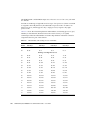
CPU Mapping
89
99
99
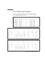
CPU Numbering Examples
I/O Device Mapping
101
102
I/O Device Mapping on Entry-Level Servers
103
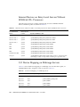
Internal Devices on Entry-Level Servers With SPARC64 VII+ Processors
103
Internal Devices on Entry-Level Servers Without SPARC64 VII+ Processors
104
I/O Device Mapping on Midrange Servers
x
SPARC Enterprise Mx000 Servers Administration Guide • June 2012
104
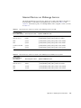
Internal Devices on Midrange Servers
105
I/O Device Mapping on High-End Servers
Internal Devices on High-End Servers
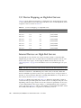
106
Internal Devices, RAID Supported
107
Internal Devices, RAID Not Supported
Sample cfgadm Output
Entry-Level Server
108
110
110
Midrange Servers
111
High-End Servers
112
Index
106
113
Contents
xi
xii
SPARC Enterprise Mx000 Servers Administration Guide • June 2012
Preface
This guide contains initial system configuration instructions for system
administration of SPARC Enterprise M3000/M4000/M5000/M8000/M9000 servers
from Oracle and Fujitsu.
Some references to server names and document names are abbreviated for
readability. For example, if you see a reference to the M9000 server, note that the full
product name is the SPARC Enterprise M9000 server. And if you see a reference to
the XSCF Reference Manual, note that the full document name is the SPARC Enterprise
M3000/M4000/M5000/M8000/M9000 Servers XSCF Reference Manual.
Besides this document, you also should read, at minimum, the overview guide for
your server.
The XCP version described in this document might no longer be the latest available
version, or the version now installed. Always see the Product Notes that apply to the
firmware on your server, and those that apply to the latest firmware release.
This chapter includes the following sections:
■
“Audience” on page xiv
■
“Related Documentation” on page xiv
■
“Text Conventions” on page xvi
■
“Syntax of the Command-Line Interface (CLI)” on page xvi
■
“Documentation Feedback” on page xvii
xiii
Audience
This guide is written for experienced system administrators with working
knowledge of computer networks and advanced knowledge of the Oracle Solaris
Operating System (Oracle Solaris OS).
Related Documentation
All documents for your server are available online at the following locations:
Documentation
Link
Sun Oracle software-related manuals
(Oracle Solaris OS, and so on)
http://www.oracle.com/documentation
Fujitsu documents
http://www.fujitsu.com/sparcenterprise/manual/
Oracle M-series server documents
http://www.oracle.com/technetwork/documentation/spar
c-mseries-servers-252709.html
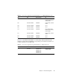
The following table lists titles of related documents.
Related SPARC Enterprise M3000/M4000/M5000/M8000/M9000 Servers Documents
SPARC Enterprise M3000 Server Site Planning Guide
SPARC Enterprise M4000/M5000 Servers Site Planning Guide
SPARC Enterprise M8000/M9000 Servers Site Planning Guide
SPARC Enterprise Equipment Rack Mounting Guide
SPARC Enterprise M3000 Server Getting Started Guide*
SPARC Enterprise M4000/M5000 Servers Getting Started Guide*
SPARC Enterprise M8000/M9000 Servers Getting Started Guide*
SPARC Enterprise M3000 Server Overview Guide
SPARC Enterprise M4000/M5000 Servers Overview Guide
SPARC Enterprise M8000/M9000 Servers Overview Guide
SPARC Enterprise M3000/M4000/M5000/M8000/M9000 Servers Important Legal and Safety Information
SPARC Enterprise M3000 Server Safety and Compliance Guide
xiv
SPARC Enterprise Mx000 Servers Administration Guide • June 2012
*
Related SPARC Enterprise M3000/M4000/M5000/M8000/M9000 Servers Documents
SPARC Enterprise M4000/M5000 Servers Safety and Compliance Guide
SPARC Enterprise M8000/M9000 Servers Safety and Compliance Guide
External I/O Expansion Unit Safety and Compliance Guide
SPARC Enterprise M4000 Server Unpacking Guide*
SPARC Enterprise M5000 Server Unpacking Guide*
SPARC Enterprise M8000/M9000 Servers Unpacking Guide*
SPARC Enterprise M3000 Server Installation Guide
SPARC Enterprise M4000/M5000 Servers Installation Guide
SPARC Enterprise M8000/M9000 Servers Installation Guide
SPARC Enterprise M3000 Server Service Manual
SPARC Enterprise M4000/M5000 Servers Service Manual
SPARC Enterprise M8000/M9000 Servers Service Manual
External I/O Expansion Unit Installation and Service Manual
SPARC Enterprise M4000/M5000/M8000/M9000 Servers Administration Guide
SPARC Enterprise M4000/M5000/M8000/M9000 Servers XSCF User’s Guide
SPARC Enterprise M4000/M5000/M8000/M9000 Servers XSCF Reference Manual
SPARC Enterprise M4000/M5000/M8000/M9000 Servers Dynamic Reconfiguration (DR) User’s Guide
SPARC Enterprise M4000/M5000/M8000/M9000 Servers Capacity on Demand (COD) User’s Guide
SPARC Enterprise M3000/M4000/M5000/M8000/M9000 Servers Product Notes†
SPARC Enterprise M3000 Server Product Notes
SPARC Enterprise M4000/M5000 Servers Product Notes
SPARC Enterprise M8000/M9000 Servers Product Notes
External I/O Expansion Unit Product Notes
SPARC Enterprise M3000/M4000/M5000/M8000/M9000 Servers Glossary
* This is a printed document.
† Beginning with the XCP 1100 release.
Preface
xv
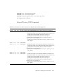
Text Conventions
This manual uses the following fonts and symbols to express specific types of
information.
Font/Symbol
Meaning
Example
AaBbCc123
What you type, when contrasted
with on-screen computer output.
This font represents the example of
command input in the frame.
XSCF> adduser jsmith
AaBbCc123
The names of commands, files, and
directories; on-screen computer
output.
This font represents the example of
command output in the frame.
XSCF> showuser -P
User Name:
jsmith
Privileges: useradm
auditadm
Italic
Indicates the name of a reference
manual, a variable, or userreplaceable text.
See the SPARC Enterprise
M4000/M5000/M8000/M9000 Servers
XSCF User’s Guide.
""
Indicates names of chapters,
sections, items, buttons, or menus.
See Chapter 2, "System Features."
Syntax of the Command-Line Interface
(CLI)
The command syntax is as follows:
xvi
■
A variable that requires input of a value must be put in Italics.
■
An optional element must be enclosed in [].
■
A group of options for an optional keyword must be enclosed in [] and delimited
by |.
SPARC Enterprise Mx000 Servers Administration Guide • June 2012
Documentation Feedback
If you have any comments or requests regarding this document, go to the following
websites:
■
For Oracle users:
http://www.oracle.com/goto/docfeedback
Include the title and part number of your document with your feedback:
SPARC Enterprise M3000/M4000/M5000/M8000/M9000 Servers Administration Guide,
part number E21618-02
■
For Fujitsu users:
http://www.fujitsu.com/global/contact/computing/sparce_index.html
Preface
xvii
xviii
SPARC Enterprise Mx000 Servers Administration Guide • June 2012
CHAPTER
1
Introduction to Server Software and
Configuration
This manual describes initial system configuration of the SPARC Enterprise
M3000/M4000/M5000/M8000/M9000 servers. This product line has entry-level
(M3000), midrange (M4000 and M5000) and high-end (M8000 and M9000) servers.
Note – The midrange and high-end servers support the following features, while
the entry-level server does not: Dynamic Reconfiguration (DR), multiple domains,
PCI hotplug, Capacity on Demand (COD), and the optional External I/O Expansion
Unit.
Once you have completed the initial configuration processes described here, see the
SPARC Enterprise M3000/M4000/M5000/M8000/M9000 Servers XSCF User’s Guide for
day-to-day system administration and management tasks.
This chapter provides an overview of server firmware, server software, and initial
system configuration. It has these sections:
■
“XSCF Firmware” on page 2
■
“Oracle Solaris OS Software” on page 2
■
“Software Services” on page 3
■
“Preparing for System Configuration” on page 5
■
“Related Information” on page 6
1
XSCF Firmware
Your server provides system management capabilities through eXtended System
Control Facility (XSCF) firmware, pre-installed at the factory on the Service
Processor1 boards.
The XSCF firmware consists of system management applications and two user
interfaces to configure and control them:
■
XSCF Web, a browser-based graphical user interface
■
XSCF Shell, a terminal-based command-line interface
You can access the XSCF firmware by logging in to the XSCF command shell. This
document includes instructions for using the XSCF interface as part of the initial
system configuration. For more information about the XSCF firmware, see Chapter 2,
and the SPARC Enterprise M3000/M4000/M5000/M8000/M9000 Servers XSCF User’s
Guide.
XSCF firmware, OpenBoot PROM firmware, and power-on self-test (POST) firmware
are known collectively as the XSCF Control Package (XCP).
XSCF firmware has two networks for internal communication. The Domain to
Service Processor Communications Protocol (DSCP) network provides an internal
communication link between the Service Processor and the Oracle Solaris domains.
The Inter-SCF Network (ISN) provides an internal communication link between the
two Service Processors in a high-end server.
On a high-end server with two Service Processors, one Service Processor is
configured as active and the other is configured as standby. This redundancy of two
Service Processors allows them to exchange system management information and, in
case of failover, to change roles. All configuration information on the active Service
Processor is available to the standby Service Processor.
Oracle Solaris OS Software
The Oracle Solaris OS is pre-installed at the factory on one domain by default.
Within its domain, the Oracle Solaris OS includes features to manage Oracle Solaris
OS system capabilities.
1. The Service Processor is sometimes referred to as the XSCF Unit, or XSCFU.
2
SPARC Enterprise Mx000 Servers Administration Guide • June 2012
Note – The XSCF firmware requires that all domains have the SUNWsckmr and
SUNWsckmu.u packages. Since the Core System, Reduced Network, and Minimal
System versions of the Oracle Solaris OS do not automatically install these packages,
you must do so on any such domains that do not already have them.
You can install applications on the domains. That process is managed through the
Oracle Solaris OS tools. Likewise, any other software management applications that
you prefer to use on the domains must be installed through the Oracle Solaris OS
tools.
The DSCP network provides an internal communication link between the Service
Processor and the Oracle Solaris domains.
Software Services
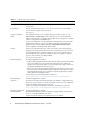
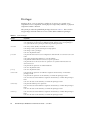
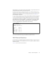
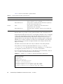
TABLE 1-1 contains an overview of XSCF firmware services and networks that are
part of your server, and where they are documented.
TABLE 1-1
Software Services
Service
Description
Access control
Access control includes logging in to the system, user accounts, passwords,
privileges, and XSCF firmware control.
See Chapter 2.
Initial system
configuration
Initial configuration of the services for the Service Processor and the domains,
including DSCP network, XSCF network, DNS name service, LDAP service, NTP
service, HTTPS service, Telnet service, SSH service, SNMP service, and SMTP
service.
See Chapter 3.
Domain configuration
Each domain runs its own copy of the Oracle Solaris OS. Domains are managed by
the Service Processor XSCF firmware, and communicate with the Service Processor
over the DSCP network. You can access a domain console from the Service Processor
or, if your system is networked, log in to a domain directly.
See Chapter 4.
Managing Disks
RAID technology enables the construction of a logical volume made up of several
physical disks to provide data redundancy, improved performance, or both.
The on-board SAS controller of M3000 servers with SPARC64 VII+ processors
supports RAID 1 (mirroring) volumes using the Oracle Solaris OS raidctl utility.
See Chapter 5.
Chapter 1
Introduction to Server Software and Configuration
3
TABLE 1-1
Software Services (Continued)
Service
Description
Auditing
The auditing function logs all security-related events.
See Chapter 6.
Log archiving
The log archiving function allows you to set up a remote host to automatically
receive and store log data from your server.
See Chapter 7.
Capacity on demand
(COD)
The COD feature allows you to configure spare processing resources on your
M4000/M5000 or M8000/M9000 server in the form of one or more COD CPUs
which can be activated at a later date when additional processing power is needed.
COD is not supported on the M3000 server
To access each COD CPU, you must purchase a COD hardware activation permit.
Under certain conditions, you can use COD resources before purchasing COD
permits for them. See the SPARC Enterprise M4000/M5000/M8000/M9000
Servers Capacity on Demand (COD) User’s Guide.
Security
Security is provided through access control (user names, passwords, privileges),
audit logs of security-related events, and various security protocols. Your server is
secure by default. That is, other than setting up user accounts and privileges, no
initial configuration has to be done related to security. For example, no insecure
protocols, such as Telnet, are initially enabled.
See Chapter 2 and Chapter 6.
Fault management
No initial configuration is needed.
• Domain fault management includes CPU, memory, and I/O (PCI/PCIe) nonfatal
errors. All nonfatal errors are reported to the Oracle Solaris OS, which will
attempt to take faulty CPUs offline or to retire faulty memory pages. Fatal errors
are generally handled by the Service Processor.
• Service Processor fault management includes fatal CPU, memory, and I/O errors
(the Service Processor will exclude the faulty components upon reboot), as well as
environmental monitoring (power supplies, fan speeds, temperatures, currents)
and the External I/O Expansion Unit.
See the Oracle Solaris OS documentation collection at
http://www.oracle.com/technetwork/documentation/index.html
Hot-replacement
operations
No initial configuration is needed.
PCI cards can be removed and inserted while your midrange or high-end (but not
entry-level) server continues to operate. The Oracle Solaris OS cfgadm command is
used to unconfigure and disconnect a PCI card.
See the Service Manual, and the Oracle Solaris OS documentation collection at
http://www.oracle.com/technetwork/documentation/index.html
External I/O Expansion
Unit management
No initial configuration is needed.
The External I/O Expansion Unit on midrange and high-end (but not entry-level)
servers is a rack mountable PCI card chassis.
See the External I/O Expansion Unit Installation and Service Manual.
4
SPARC Enterprise Mx000 Servers Administration Guide • June 2012
Preparing for System Configuration
This section lists the information needed for initial system configuration and the
initial configuration tasks.
Information Needed
Before you configure the software, have the following available:
■
Access to the Service Processor with the appropriate privileges for your tasks.
More information about access is contained in Chapter 2.
■
An unused range of IP addresses for the internal DSCP network between the
Service Processor and the domains.
■
Network configuration information for the Service Processor, including IP
addresses, netmask, DNS server, default route, NFS server.
■
The number of domains in your system. By default, there is one domain and its
domain number is 0 (zero). The number of domains could be different from the
default on midrange or high-end (but not entry-level) servers if you specified
another number of domains when you ordered your system.
■
Firmware version information if you are upgrading the XSCF firmware.
■
Information for optional services that you are going to use, such as Lightweight
Directory Access Protocol (LDAP) information for authentication.
Initial Configuration Tasks
Initial configuration requires these tasks:
1. Logging in to the Service Processor with the default log-in name over a serial
connection. You must have physical access to the system.
2. Adding at least one user account with a minimum of one privilege, useradm.
This user with useradm privileges can then create the rest of the user accounts.
3. Configuring the DSCP network.
4. Configuring the XSCF network.
5. Setting the Service Processor time. The Service Processor can be an NTP client, or
an NTP client and NTP server for the domains.
Chapter 1
Introduction to Server Software and Configuration
5
6. Configuring or enabling any optional services you want to use immediately.
These services include Telnet, SNMP, SMTP, LDAP, NTP, HTTPS, DNS, SSH,
domains, log archiving, and COD. COD is not supported on the M3000 server.
Related Information
For additional information on this chapter’s topics, see:
Resource
Information
man pages (see the Note following this table)
fmdump(8), fmadm(8), fmstat(8), version(8),
cfgadm(1M)
Site Planning Guide
Site planning
SPARC Enterprise M3000/M4000/M5000/M8000/M9000
Servers XSCF User’s Guide
System configuration and administration
Oracle Solaris OS documentation collection at
http://www.oracle.com/technetwork/documen
tation/index.html
Oracle Solaris OS, including fault management.
Service Manual
Hot-replacement operations, fault management
External I/O Expansion Unit Installation and Service
Manual
PCI card chassis
Note – man pages available on the Service Processor are followed by (8), for
example, version(8); they are also available in the SPARC Enterprise
M3000/M4000/M5000/M8000/M9000 Servers XSCF Reference Manual. Oracle Solaris OS
man pages available on the domains are followed by (1M), for example,
cfgadm(1M).
6
SPARC Enterprise Mx000 Servers Administration Guide • June 2012
CHAPTER
2
Access Control
Access control is a way of granting access to the system functions or components
only to those users who have been authenticated by the system and who have
appropriate privileges. Access control depends on the proper configuration of the
general security services provided by the server.
This chapter contains these sections:
■
“About Access Control” on page 7
■
“Saving and Restoring XSCF Configuration Information” on page 12
■
“XSCF Shell Procedures for Access Control” on page 12
■
“Related Information” on page 18
About Access Control
The Service Processor is an appliance. In an appliance model, users or management
agents can access the Service Processor and its components only through authorized
user interfaces. Users and agents cannot access any of the underlying operating
system interfaces, and users cannot install individual software components on the
Service Processor.
These sections provide details on access control:
■
“Logging in to the System” on page 8
■
“Lockout Period Between Login Attempts” on page 8
■
“XSCF User Accounts” on page 9
■
“XSCF Passwords” on page 9
■
“Privileges” on page 10
■
“XSCF Firmware Update” on page 11
7
Logging in to the System
There are two entities that can be logged in to on the system, a Service Processor and
an Oracle Solaris domain.
You initially log in to the Service Processor using a serial connection from a terminal
device. A terminal device can be an ASCII terminal, a workstation, or a PC. For
details on serial port connections, see the Installation Guide for your server or the
SPARC Enterprise M3000/M4000/M5000/M8000/M9000 Servers XSCF User’s Guide.
A unique login account with the user name of default exists on the Service
Processor. This account is unique in the following ways:
■
It can never be logged in to using the standard UNIX user name and password
authentication or SSH public key authentication.
■
It can only be logged in to using a procedure that requires physical access to the
system.
■
Its privileges are fixed to be useradm and platadm; you cannot change these
privileges.
■
It cannot be deleted, it has no password, and no password can be set for it.
After initial configuration, you can log in to the Service Processor using a serial
connection or an Ethernet connection. You can redirect the XSCF console to a domain
and get an Oracle Solaris console. You can also log in to a domain directly using an
Ethernet connection to access the Oracle Solaris OS.
When a user logs in, the user establishes a session. Authentication and user
privileges are valid only for that session. When the user logs out, that session ends.
To log back in, the user must be authenticated once again, and will have the
privileges in effect during the new session. See “Privileges” on page 10 for
information on privileges.
Lockout Period Between Login Attempts
After multiple XSCF login failures, no further login attempts are allowed for a
certain amount of time. To set the lockout period, use the setloginlockout(8)
command. To view the lockout period, use the showloginlockout(8) command.
For more information, see the setloginlockout(8) and showloginlockout(8)
man pages.
Note – The ability to specify and view the lockout period was added in a recent
XCP update. Please see the Product Notes for the firmware release running on your
server (no earlier than the XCP 1080 release) for possible restrictions.
8
SPARC Enterprise Mx000 Servers Administration Guide • June 2012
XSCF User Accounts
A user account is a record of an individual user that can be verified through a user
name and password.
When you initially log in to the system, add at least one user account with a
minimum of one privilege, useradm. This user with useradm privileges can then
create the rest of the user accounts. For a secure log in method, enable SSH service.
See “To Enable or Disable the Service Processor SSH Service” on page 45 and to “To
Generate a Host Public Key for SSH Service” on page 46 for more information.
Note – You cannot use the following user account names, as they are reserved for
system use: root, bin, daemon, adm, operator, nobody, sshd, rpc, rpcuser, ldap,
apache, ntp, admin, and default.
XSCF supports multiple user accounts for log in to the Service Processor. The user
accounts are assigned privileges; each privilege allows the user to execute certain
XSCF commands. By specifying privileges for each user, you can control which
operations each XSCF user is allowed to perform. On its own, a user account has no
privileges. To obtain permission to run XSCF commands and access system
components, a user must have privileges.
You can set up the Service Processor to use an LDAP server for authentication
instead. To use LDAP, the Service Processor must be set up as an LDAP client. For
information about setting up the Service Processor to use the LDAP service, see
“LDAP Service” on page 23. If you are using an LDAP server for authentication, the
user name must not be in use, either locally or in LDAP.
XSCF Passwords
User passwords are authenticated locally by default unless you are using an LDAP
server for authentication.
Site-wide policies, such as password nomenclature or expiration dates, make
passwords more difficult to guess. You can configure a password policy for the
system using the setpasswordpolicy command. The setpasswordpolicy
command describes the default values for a password policy.
If you have lost password access to your system, use the procedure “To Log in
Initially to the XSCF Console” on page 13.
Chapter 2
Access Control
9
Privileges
Privileges allow a user to perform a specific set of actions on a specific set of
components. Those components can be physical components, domains, or physical
components within a domain.
The system provides the predefined privileges shown in TABLE 2-1. These are the
only privileges allowed in the server. You cannot define additional privileges.
TABLE 2-1
User Privileges
Privilege
Capabilities
none
None. When the local privilege for a user is set to none, that user has no privileges,
even if privileges for that user are defined in LDAP. Setting a user’s local privilege to
none prevents the user’s privileges from being looked up in LDAP.
useradm
Can
Can
Can
Can
platadm
Can perform all Service Processor configuration other than the useradm and auditadm
tasks.
Can assign and unassign hardware to or from domains.
Can perform domain and Service Processor power operations.
Can perform Service Processor failover operations on systems with more than one
Service Processor.
Can perform all operations on domain hardware.
Can view all platform states.
platop
Can view all platform states.
domainadm
Can perform all operations on hardware assigned to the domain(s) on which this
privilege is held.
Can perform all operations on the domain(s) on which this privilege is held.
Can view all states of the hardware assigned to the domain(s) on which this privilege is
held.
Can view all states of the domain(s) on which this privilege is held.
domainmgr
Can perform domain power operations.
Can view all states of the hardware assigned to the domain(s) on which this privilege is
held.
Can view all states of the domain(s) on which this privilege is held.
domainop
Can view all states of the hardware assigned to the domain(s) on which this privilege is
held.
Can view all states of the domain(s) on which this privilege is held.
10
create, delete, disable, and enable user accounts.
change a user’s password and password properties.
change a user’s privileges.
view all platform states.
SPARC Enterprise Mx000 Servers Administration Guide • June 2012
TABLE 2-1
User Privileges (Continued)
Privilege
Capabilities
auditadm
Can configure auditing.
Can delete audit trail.
auditop
Can view all audit states and the audit trail.
fieldeng
Can perform all operations reserved for field engineers.
The domainadm, domainmgr, and domainop privileges must include the domain
number, numbers, or range of numbers to associate with a particular user account.
A user can have multiple privileges, and a user can have privileges on multiple
domains.
User privileges are authenticated locally by default. You can set up the Service
Processor to use an LDAP server for authentication instead. For information about
setting up the Service Processor to use the LDAP service, see “LDAP Service” on
page 23.
If no privileges are specified for a user, no local privilege data will exist for that user;
however, the user’s privileges can be looked up in LDAP, if LDAP is being used. If a
user’s privileges are set to none, that user does not have any privileges, regardless
of privilege data in LDAP.
XSCF Firmware Update
The Service Processor firmware can only be updated as an entire image, known as an
XCP image. The image includes the XSCF firmware, OpenBoot PROM firmware,
POST firmware, and miscellaneous files. Only valid images authorized by Oracle or
Fujitsu can be installed.
The XCP image is installed in the Service Processor flash memory. You need
platadm or fieldeng privilege to update an XCP image. More information on
updating an XCP image is contained in the SPARC Enterprise
M3000/M4000/M5000/M8000/M9000 Servers XSCF User’s Guide.
Chapter 2
Access Control
11
Saving and Restoring XSCF
Configuration Information
To save and restore XSCF configuration information, use the dumpconfig(8) and
restoreconfig(8) commands in the XSCF shell. The commands permit you to
specify the location where the information is to be stored and retrieved. For more
information, see the SPARC Enterprise M3000/M4000/M5000/M8000/M9000 Servers
XSCF User’s Guide and the dumpconfig(8) and restoreconfig(8) man pages.
Note – The XCP 1080 firmware is the first XCP release to support the
dumpconfig(8) and restoreconfig(8) commands.
XSCF Shell Procedures for Access
Control
This section describes these procedures:
12
■
“To Log in Initially to the XSCF Console” on page 2-13
■
“To Configure an XSCF Password Policy” on page 2-15
■
“To Add an XSCF User Account” on page 2-16
■
“To Create a Password for an XSCF User” on page 2-16
■
“To Assign Privileges to an XSCF User” on page 2-17
■
“To Display the Version of Installed Firmware” on page 2-17
SPARC Enterprise Mx000 Servers Administration Guide • June 2012
▼ To Log in Initially to the XSCF Console
This procedure can be used for initial login or for lost password access.
1. Log in to the XSCF console with the default login name from a terminal device
connected to the Service Processor. You must have physical access to the
system.
serial port log-in prompt: default
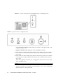
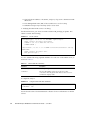
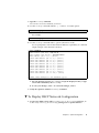
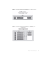
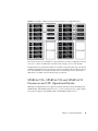
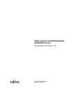
You are prompted to toggle the Operator Panel MODE switch (keyswitch) on the
front of the system. The location of the MODE switch on an entry-level server is
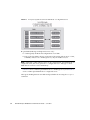
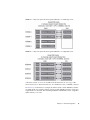
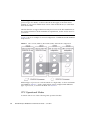
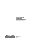
shown in FIGURE 2-1. The location of the MODE switch on a midrange server is
shown in FIGURE 2-2. And the MODE switch on a high-end server is mounted
horizontally rather than vertically, as shown in FIGURE 2-3. The MODE switch has
two positions: Service and Locked.
Note – In the following illustrations, the three LEDs appear first, followed by the
POWER button, then the MODE switch.
FIGURE 2-1
Location of the Operator Panel MODE Switch on an Entry-Level Server
Chapter 2
Access Control
13
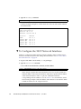
FIGURE 2-2
FIGURE 2-3
Location of the Operator Panel MODE Switch on a Midrange Server
Operator Panel on a High-end Server
You must toggle the MODE switch within one minute of the login prompt or the
login process times out.
2. Toggle the MODE switch using one of two methods, as follows:
■
If the switch is in the Service position, turn it to the Locked position, leave it there
for at least five seconds, and then turn it back to the Service position. Press the
Enter key.
■
If the switch is in the Locked position, turn it to the Service position, leave it there
for at least five seconds, and then turn it back to the Locked position. Press the
Enter key.
When the toggling is successful, you are logged in to the Service Processor shell
as the account default.
XSCF>
As this account has useradm and platadm privileges. you can now configure the
Service Processor or reset passwords.
14
SPARC Enterprise Mx000 Servers Administration Guide • June 2012
When the shell session ends, the default account is disabled. When an account is
disabled, it cannot be used to log in at the console. It will then not be possible to
login using this account again except by following this same procedure.
Note – You can use the setupplatform(8) command rather than the following
procedures to perform Service Processor installation tasks. For more information, see
the setupplatform(8) man page.
▼ To Configure an XSCF Password Policy
1. Log in to the XSCF console with useradm privileges.
2. Type the setpasswordpolicy command:
XSCF> setpasswordpolicy option
where option can be one or more of the options described in the
setpasswordpolicy(8) man page.
Note – The password policy applies only to users added after the
setpasswordpolicy(8) command has been executed.
3. Verify that the operation succeeded by typing the showpasswordpolicy
command.
▼ To Add an XSCF User Account
When you add a new user account, the account has no password, and cannot be
used for logging in until the password is set or Secure Shell public key
authentication is enabled for the user.
1. Log in to the XSCF console with useradm privileges.
2. Type the adduser command:
XSCF> adduser user
where user is the user name you want to add. (See the adduser(8) man page for
rules about the user name.) If you do not specify a User ID (UID) number with the
-u UID option, one is automatically assigned, starting from 100.
Chapter 2
Access Control
15
3. Verify that the operation succeeded by typing the showuser command.
▼ To Create a Password for an XSCF User
Any XSCF user can set his or her own password. Only a user with useradm
privileges can set another user’s password.
1. Log in to the XSCF console with useradm privileges.
2. Type the password command:
XSCF> password
Please enter your password:
See the password(8) man page for rules about passwords. When typed without
an argument, password sets the current user’s password. To set someone else’s
password, include that person’s user name, for example:
XSCF> password user
Please enter your password:
where user is the user name you want to set the password for. You are prompted
to enter, and then reenter, the password.
16
SPARC Enterprise Mx000 Servers Administration Guide • June 2012
▼ To Assign Privileges to an XSCF User
1. Log in to the XSCF console with useradm privileges.
2. Type the setprivileges command:
XSCF> setprivileges user privileges
where user is the user name to assign privileges for, and privileges is one or more
privileges, separated by a space, to assign to this user. The domainadm,
domainmgr, and domainop privileges must include the domain number,
numbers, or range of numbers to associate with a particular user account; for
example,
XSCF> setprivileges user domainadm@1-4, 6, 9
Valid privileges are listed in TABLE 2-1.
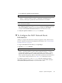
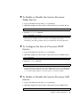
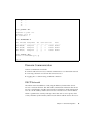
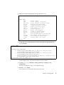
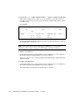
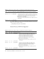
▼ To Display the Version of Installed Firmware
1. Log in to the XSCF console with platadm or fieldeng privileges.
2. Type the version command:
XSCF> version -c xcp
The XCP version number is displayed. Command output example is:
XSCF> version -c xcp
XSCF#0(Active)
XCP0 (Current): 1080
...
Chapter 2
Access Control
17
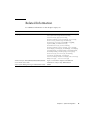
Related Information
For additional information on this chapter’s topics, see:
Resource
Information
man pages
password(8), version(8), adduser(8), deleteuser(8),
enableuser(8), disableuser(8), showuser(8),
setpasswordpolicy(8), setprivileges(8),
showpasswordpolicy(8), setlookup(8), setldap(8), showldap(8)
SPARC Enterprise
M3000/M4000/M5000/M8000/M9000
Servers XSCF User’s Guide
Access control, user accounts, passwords, firmware update
18
SPARC Enterprise Mx000 Servers Administration Guide • June 2012
CHAPTER
3
System Configuration
This chapter describes how to initially configure system services and internal
networks that enable communication between the components of your server.
This chapter contains these sections:
■
“About System Services” on page 19
■
“XSCF Shell Procedures for System Configuration” on page 29
■
“Related Information” on page 47
About System Services
Your server uses various services to enable communication between its components.
See “Preparing for System Configuration” on page 5 for an overview of initial
service configuration.
These sections provide details on system services:
■
“DSCP Network Between a Service Processor and a Domain” on page 20
■
“XSCF Network Interfaces” on page 21
■
“Domain Name Service” on page 23
■
“LDAP Service” on page 23
■
“Active Directory and LDAP/SSL” on page 25
■
“Time Synchronization and NTP Service” on page 25
■
“SNMP Service” on page 27
■
“Additional Services” on page 28
19
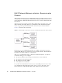
DSCP Network Between a Service Processor and a
Domain
The Domain to Service Processor Communications Protocol (DSCP) service provides
a secure TCP/IP- and PPP-based communication link between the Service Processor
and each domain. Without this link, the Service Processor cannot communicate with
the domains.
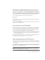
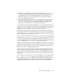
The Service Processor requires one IP address dedicated to the DSCP service on its
side of the link, and one IP address on each domain’s side of the link. The DSCP
service is a point-to-point link between the Service Processor and each domain.
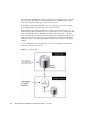
FIGURE 3-1 illustrates this relationship.
FIGURE 3-1
Relationship of the Service Processor and the DSCP Network to the Domains
DSCP service is not configured by default. You configure and use the service by
specifying IP addresses for the Service Processor and the domains. The IP addresses
should be nonroutable addresses on the network.
The setdscp command provides an interactive mode that displays a prompt for
each DSCP setting you can configure:
■
The network address to be used by the DSCP network for IP addresses
■
The netmask for the DSCP network
■
The Service Processor IP address
■
An IP address for each domain
In a system with redundant Service Processors, the standby Service Processor does
not communicate with the domains. In the event of a failover, the newly active
Service Processor assumes the IP address of the failed-over Service Processor.
20
SPARC Enterprise Mx000 Servers Administration Guide • June 2012
DSCP includes its own security measures that prohibit a compromised domain from
compromising other domains or the Service Processor.
The DSCP should only be configured when there are no domains running. If you
change the DSCP configuration while a domain is active, you have to power off the
domain before the Service Processor can communicate with it. See Chapter 4 for
more information on domains.
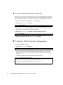
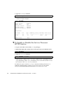
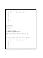
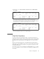
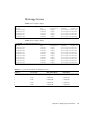
In a typical DSCP configuration, you enter a network address and netmask using the
setdscp command. The system then configures the Service Processor IP address
and any domain IP addresses according to this formula: the Service Processor gets
an IP address that is the network address +1; and each domain gets an IP address
that is the Service Processor IP address, + the domain ID, +1. For example, if you
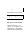
enter 10.1.1.0 for the network address, and 255.255.255.0 for the netmask, the
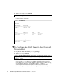
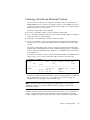
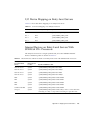
showdscp command displays output similar to the following:
XSCF> showdscp
DSCP Configuration:
Network: 10.1.1.0
Netmask: 255.255.255.0
Location
XSCF
Domain #00
Domain #01
Domain #02
Domain #03
...
Address
10.1.1.1
10.1.1.2
10.1.1.3
10.1.1.4
10.1.1.5
This scenario minimizes the range of IP addresses needed for DSCP.
XSCF Network Interfaces
The XSCF network configurable settings include the IP address for the active Service
Processor, IP address for the standby Service Processor, gateway address, netmask,
and network route.
TABLE 3-1 lists the XSCF network interfaces.
Chapter 3
System Configuration
21
TABLE 3-1
XSCF Network Interfaces
XSCF Unit
Interface Name
Description
XSCF Unit 0
(entry-level, midrange, and
high-end servers)
xscf#0-lan#0
XSCF LAN#0 (external)
xscf#0-lan#1
XSCF LAN#1 (external)
xscf#0-if
Interface between XSCF Units (ISN: Inter
SCF Network); high-end server only
xscf#1-lan#0
XSCF LAN#0 (external)
xscf#1-lan#1
XSCF LAN#1 (external)
xscf#1-if
Interface between XSCF Units (ISN)
lan#0
Takeover IP address for XSCF LAN#0
lan#1
Takeover IP address for XSCF LAN#1
XSCF Unit 1
(high-end server only)
On a high-end server, one Service Processor is configured as active and the other is
configured as standby. The XSCF network between the two Service Processors allows
them to exchange system management information and, in case of failover, to change
roles. When the XSCF unit is configured with redundancy, ISN addresses must be in
the same network subnet.
Optionally, a takeover IP address can be set up, which is hosted on the currently
active Service Processor. External clients can use this takeover IP address to connect
to whichever Service Processor is active. Selection of a takeover IP address does not
affect failover.
When you set or change the information related to the XSCF network, including the
Service Processor host name, DNS domain name, DNS server, IP address, netmask,
or routing information, you must make the changes effective in XSCF and reset the
Service Processor. This is done with the applynetwork and rebootxscf
commands.
You configure the XSCF network with these commands:
22
■
setnetwork
■
setroute
■
sethostname (if using DNS)
■
setnameserver (if using DNS)
■
applynetwork
SPARC Enterprise Mx000 Servers Administration Guide • June 2012
Once you have configured the XSCF network, it requires no day-to-day
management.
Domain Name Service
The Domain Name Service (DNS) allows computers on a network to communicate
with each other by using centrally maintained DNS names instead of locally stored
IP addresses. If you configure the Service Processor to use the DNS service, it “joins”
the DNS community and can communicate with any other computer on the network
through its DNS server.
There are no defaults for this service. To configure the Service Processor to use DNS,
you must specify the Service Processor host name, and the DNS server name and IP
address.
You can configure the Service Processor DNS service with these commands:
■
sethostname
■
setnameserver
On a server with dual Service Processors, the domain name is common for both
Service Processors. A host name can be specified for each Service Processor. Setting a
different host name for each Service Processor does not disable failover.
Once you have configured the Service Processor to use the DNS service, it does not
require day-to-day management.
LDAP Service
The LDAP service stores user authentication and privilege settings on a server so
that individual computers on the network do not have to store the settings.
By default, the Service Processor stores user passwords and privileges locally.
Account information for users who have access to the Service Processor are stored
on the Service Processor itself. (Authentication and privilege lookups for the server’s
domains are provided by the Oracle Solaris OS.)
However, if you want to have authentication and privilege lookups performed by an
LDAP server, you can set up the Service Processor to be an LDAP client.
The general process for setting up the Service Processor as an LDAP client is:
1. Enabling the LDAP service.
2. Providing the LDAP server configuration information:
■
The IP address or hostname, and port, of the primary LDAP directory
Chapter 3
System Configuration
23
■
Optional: The IP address or hostname, and port, of up to two alternative LDAP
directories
■
The distinguished name (DN) of the search base to use for lookup
■
Whether Transport Layer Security (TLS) is to be used
3. Verifying that the LDAP service is working.
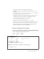
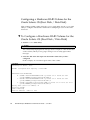
On the LDAP server, you create an LDAP schema with privilege properties. The
schema contains the following:
EXAMPLE 3-1
LDAP Schema
attributetype ( 1.3.6.1.1.1.1.40 NAME ’spPrivileges’
DESC ’Service Processor privileges’
SYNTAX 1.3.6.1.4.1.1466.115.121.1.26
SINGLE-VALUE )
objectclass ( 1.3.6.1.1.1.2.13 NAME ’serviceProcessorUser’ SUP top
AUXILIARY
DESC ’Service Processor user’
MAY spPrivileges )
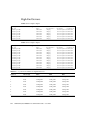
You also add the following required attributes for each user on the LDAP server, as
shown in TABLE 3-2.
TABLE 3-2
LDAP LDIF File Attributes
Field Name
Description
spPrivileges
A valid privilege on the Service Processor
uidNumber
The user ID number on the Service Processor. The
uidnumber must be greater than 100. Use the showuser
command to display UIDs.
A sample file entry is:
EXAMPLE 3-2
Sample LDAP LDIF File Attributes
spPrivileges: platadm
uidNumber: 150
See the Oracle Solaris OS documentation collection for more information on LDAP
servers.
24
SPARC Enterprise Mx000 Servers Administration Guide • June 2012
If the LDAP client is configured and enabled on the Service Processor, lookups are
first performed locally, and then through the LDAP server. If you execute the
setprivileges command for a user without specifying privileges, the command
deletes any local privilege data for that user. Subsequently, the user’s privileges will
be looked up in LDAP, if LDAP privilege lookup is enabled. If you specify privilege
as none, that user will have no privileges, regardless of privilege data in LDAP.
These commands manage the Service Processor LDAP service:
■
setlookup
■
setldap
Note that passwords stored in the LDAP repository must use either UNIX crypt or
MD5 encryption schemes.
Once you have configured the Service Processor to use the LDAP service, it does not
require day-to-day management.
Active Directory and LDAP/SSL
The XCP 1091 release introduced support for the Active Directory and LDAP/SSL
features. Some changes to these features were introduced in the XCP 1092 release.
■
Active Directory is a distributed directory service from Microsoft Corporation.
Like an LDAP directory service, it is used to authenticate users.
■
LDAP/SSL (originally called LDAP over SSL) offers enhanced security to LDAP
users by way of Secure Socket Layer (SSL) technology. It uses LDAP directory
service to authenticate users.
For information about Active Directory and LDAP/SSL, see the SPARC Enterprise
M3000/M4000/M5000/M8000/M9000 Servers XSCF User’s Guide.
Time Synchronization and NTP Service
The Network Time Protocol (NTP) provides the correct timestamp for all systems on
a network by synchronizing the clocks of all the systems. NTP service is provided by
an NTP daemon.
To use the NTP service, the Service Processor can be set up as an NTP client, using
the services of a remote NTP server. The Service Processor also can be set up as an
NTP server, as can an external resource.
Note – Check the Product Notes for your server, which may contain important
information about using the XSCF as NTP server.
Chapter 3
System Configuration
25
TABLE 3-3 shows how the time is synchronized.
TABLE 3-3
XSCF and Domain Time Synchronization
Entity
Primary NTP Server
Time Synchronization Method
XSCF
No connection
The XSCF time is the time in the initial system setting or the
time set with the setdate command.
External NTP server
XSCF operates as an NTP client. The XSCF time is adjusted to
the time of the external NTP server.
XSCF
XSCF operates as the NTP server. The domain time is
adjusted to the time of the XSCF.
External NTP server
The domain time is adjusted to the time of the external NTP
server.
Domain
When domains are powered on, they synchronize their clocks to the NTP server.
If the domain and the Service Processor are using the same time source, one benefit
is that events logged in the Oracle Solaris OS and on the Service Processor can be
correlated based on their timestamp. If the domain and Service Processor use
different NTP servers, their times may drift, and correlating log files could become
difficult. If you connect a domain to an NTP server other than the one used by the
Service Processor, be sure both are high-rank NTP servers that provide the same
degree of accuracy.
The XSCF can be used as NTP server only for domains on the same platform.
Every NTP server and every NTP client must have an ntp.conf file, in
/etc/inet/ntp.conf. The Service Processor has a default ntp.conf file. If you
are using NTP, you must create an ntp.conf file on each domain.
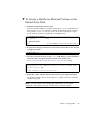
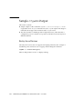
If you are using the Service Processor as the NTP server for the domains, create an
ntp.conf file on each domain similar to the following:
EXAMPLE 3-3
Sample ntp.conf File for a Domain using XSCF as NTP Server
server ip_address
slewalways yes
disable pll
enable auth monitor
driftfile /var/ntp/ntp.drift
statsdir /var/ntp/ntpstats/
filegen peerstats file peerstats type day enable
filegen loopstats file loopstats type day enable
filegen clockstats file clockstats type day enable
26
SPARC Enterprise Mx000 Servers Administration Guide • June 2012
where ip_address is the IP address you configured for the Service Processor on the
DSCP network. To display the Service Processor’s IP address, use the showdscp -s
command.
If you are using an external NTP server for the domains, see the xntpd(1M) man
page or to the Oracle Solaris OS documentation collection for information on
creating the ntp.conf file for each domain.
SNMP Service
A Simple Network Management Protocol (SNMP) agent can be configured and
enabled on the Service Processor. The Service Processor SNMP agent monitors the
state of the system hardware and domains, and exports the following information to
an SNMP manager:
■
System information such as chassis ID, platform type, total number of CPUs, and
total memory
■
Configuration of the hardware
■
Dynamic reconfiguration information, including which domain-configurable units
are assigned to which domains
■
Domain status
■
Power status
■
Environmental status
The Service Processor SNMP agent can supply system information and fault event
information using public MIBs. SNMP managers, for example, a third-party
manager application, use any Service Processor network interface with the SNMP
agent port to communicate with the agent. The SNMP agent supports concurrent
access from multiple users through SNMP managers.
By default, the SNMP agent uses version 3 (v3) of the SNMP protocol. SNMP v3 is
secure, requiring an authentication protocol, authentication password, and
encryption password. The valid authentication protocols are MD5 and SHA (secure
hash algorithm). You can also configure your server to accept earlier SNMP versions
1 and 2.
The SNMP agent includes the v3 utilities for user management, the User Security
Model (USM), and for view access control, the View Access Control Model (VACM).
You can change the configuration of SNMP agent traps, USM user accounts, and
VACM information.
Initial SNMP v3 configuration includes:
1. Creating USM user information
2. Creating VACM access control information (group, view, and access)
Chapter 3
System Configuration
27
Using VACM requires a basic knowledge of SNMP and MIBs. See the Solaris
System Management Agent Administration Guide and to the SPARC Enterprise
M3000/M4000/M5000/M8000/M9000 Servers XSCF User’s Guide for information.
3. Configuring the SNMP agent
4. Enabling the SNMP agent
5. Setting up your SNMP manager application to communicate with the Service
Processor SNMP agent based on the configuration you used for the agent, namely,
user, port, and trap information.
The SNMP agent is active only on the active Service Processor. In the event of
failover, the SNMP agent is restarted on the newly active Service Processor.
Additional Services
This section describes HTTPS, Telnet, SMTP, and SSH services, and altitude settings.
This section does not cover all the optional services and settings for the Service
Processor that you might want to set up and use at a later date. For example, you
can set up mirrored memory mode using the setupfru command. See the SPARC
Enterprise M3000/M4000/M5000/M8000/M9000 Servers XSCF User’s Guide for
information on day-to-day administration and management tasks.
HTTPS Service
Hypertext Transfer Protocol (HTTP) over an authenticated/encrypted connection
allows you to use the XSCF web browser securely. This is called the HTTPS service.
Authentication is provided with a certificate authority and private keys. To use the
HTTPS service, you must enable it, and provide an optional port number. The
default port is 443. To enable HTTPS service, use the sethttps command.
Telnet Service
Telnet service is disabled by default on the Service Processor. To enable it, use the
settelnet command. Telnet provides an alternative for those sites that do not have
ssh.
28
SPARC Enterprise Mx000 Servers Administration Guide • June 2012
SMTP Service
Simple Mail Transfer Protocol (SMTP) service is controlled by these commands:
■
showsmtp
■
setsmtp
The authentication mechanisms allowed by the mail server are pop, smtp-auth, or
none (the default). The SMTP authentications supported are plain and login.
SSH Service
SSH service is disabled by default. To enable it, use the setssh command. A host
public key is required for SSH service.
Altitude Setting
The altitude for your server is set to 0 meters by default. To set it for the actual
altitude of your server, use the setaltitude command. Executing this command
causes the server to adjust the temperature thresholds it uses to protect the system
so it can more accurately detect any abnormality in the intake air temperature.
However, even if you do not set the altitude, any abnormality in air temperature,
such as CPU temperature, can still be detected. As server temperature limits are set
to protect domain hardware, execute the setaltitude command before powering
on any domain. See setaltitude(8).
Note – A modification of the altitude value takes effect only after you subsequently
execute the rebootxscf command and reset XSCF. See rebootxscf(8).
XSCF Shell Procedures for System
Configuration
This section describes these procedures:
■
“To Configure the DSCP Network” on page 3-30
■
“To Display DSCP Network Configuration” on page 3-31
■
“To Configure the XSCF Network Interfaces” on page 3-32
■
“To Configure the XSCF Network Route Information” on page 3-33
Chapter 3
System Configuration
29
■
“To Set Or Reset the XSCF Network” on page 3-34
■
“To Display XSCF Network Configuration” on page 3-34
■
“To Set the Service Processor Host Name and DNS Domain Name” on page 3-35
■
“To Set the Service Processor’s DNS Name Server” on page 3-35
■
“To Enable or Disable Use of an LDAP Server for Authentication and Privilege
Lookup” on page 3-36
■
“To Configure the XSCF as an LDAP Client” on page 3-36
■
“To Configure the XSCF as an NTP Client” on page 3-37
■
“To Configure the XSCF as an NTP Server” on page 3-37
■
“To Display the NTP Configuration” on page 3-38
■
“To Set the Timezone, Daylight Saving Time, Date, and Time Locally on the
Service Processor” on page 3-38
■
“To Create a USM User Known to the SNMP Agent” on page 3-39
■
“To Display USM Information for the SNMP Agent” on page 3-40
■
“To Create a VACM Group” on page 3-40
■
“To Create a VACM View” on page 3-41
■
“To Give a VACM Group Access to a VACM View” on page 3-41
■
“To Display VACM Information for the SNMP Agent” on page 3-41
■
“To Configure the SNMP Agent to Send Version 3 Traps to Hosts” on page 3-42
■
“To Enable the SNMP Agent” on page 3-43
■
“To Display SNMP Agent Configuration” on page 3-43
■
“To Enable or Disable the Service Processor HTTPS Service” on page 3-44
■
“To Enable or Disable the Service Processor Telnet Service” on page 3-45
■
“To Configure the Service Processor SMTP Service” on page 3-45
■
“To Enable or Disable the Service Processor SSH Service” on page 3-45
■
“To Generate a Host Public Key for SSH Service” on page 3-46
■
“To Set the Altitude on the Service Processor” on page 3-46
Note – You can use the setupplatform(8) command rather than the following
procedures to perform network installation tasks. For more information, see the
setupplatform(8) man page.
▼ To Configure the DSCP Network
1. Log in to the XSCF console with platadm or fieldeng privileges.
30
SPARC Enterprise Mx000 Servers Administration Guide • June 2012
2. Type the setdscp command.
You can use one of two methods, as follows:
■
Use the setdscp command with the -y -i address -m netmask options:
XSCF> setdscp -y -i address -m netmask
For example:
XSCF> setdscp -y -i 10.1.1.0 -m 255.255.255.0
■
Use the setdscp command with no options (interactive mode).
You are prompted to enter all the DSCP IP addresses sequentially. A command
output example of this interactive mode is:
XSCF> setdscp
DSCP network [0.0.0.0] > 10.1.1.0
DSCP netmask [255.0.0.0] > 255.255.255.0
XSCF address [10.1.1.1] > [Enter]
Domain #00 address [10.1.1.2] > [Enter]
Domain #01 address [10.1.1.3] > [Enter]
Domain #02 address [10.1.1.4] > [Enter]
Domain #03 address [10.1.1.5] > [Enter]
Domain #04 address [10.1.1.6] > [Enter]
Domain #05 address [10.1.1.7] > [Enter]
Domain #06 address [10.1.1.8] > [Enter]
Domain #07 address [10.1.1.9] > [Enter]
Domain #08 address [10.1.1.10] > [Enter]
...
Commit these changes to the database (y|n)?
a. For each prompt, press the Enter key to accept the displayed value, or type
a new value followed by the Enter key.
b. To save your changes, enter Y. To cancel the changes, enter N.
3. Verify the operation with the showdscp command.
▼ To Display DSCP Network Configuration
1. Log in to the XSCF console with platadm, platop, or fieldeng privileges, or
domainadm, domainop, or domainmgr privileges for a specific domain.
Chapter 3
System Configuration
31
2. Type the showdscp command:
XSCF> showdscp
Command output example for a DSCP network of 10.1.1.0 and a DSCP netmask
of 255.255.255.0 is:
XSCF> showdscp
DSCP Configuration:
Network: 10.1.1.0
Netmask: 255.255.255.0
Location
XSCF
Domain #00
Domain #01
Domain #02
Domain #03
...
Address
10.1.1.1
10.1.1.2
10.1.1.3
10.1.1.4
10.1.1.5
▼ To Configure the XSCF Network Interfaces
Settings to configure the XSCF network must be applied to XSCF, and the Service
Processor must be reset, before the settings become effective. See “To Set Or Reset
the XSCF Network” on page 34.
1. Log in to the XSCF console with platadm privileges.
2. Type the setnetwork command:
a. To set the network interface, netmask, and IP address:
XSCF> setnetwork interface [-m addr] address
where interface specifies the network interface to be set, -m addr specifies the
netmask address of the network interface, and address specifies the IP address
of the network interface. If the -m option is omitted, the netmask
corresponding to the IP address is set. See TABLE 3-1 for valid interface names.
The following example sets the IP address and netmask for the interface XSCFLAN#0 on XSCF Unit 1 in a high-end server:
XSCF> setnetwork xscf#1-lan#0 -m 255.255.255.0 192.168.11.10
32
SPARC Enterprise Mx000 Servers Administration Guide • June 2012
b. To enable the specified network interface:
XSCF> setnetwork -c [up|down] interface
where -c specifies whether to enable or disable the specified network
interface, and interface specifies the network interface to be enabled.
Note – When the XSCF unit is configured with redundancy, ISN addresses must be
in the same network subnet.
For additional information on the setnetwork command, including specifying
takeover IP addresses, see the setnetwork(8) man page or to the SPARC
Enterprise M3000/M4000/M5000/M8000/M9000 Servers XSCF User’s Guide.
3. Verify the operation with the shownetwork command.
▼ To Configure the XSCF Network Route
Information
Settings to configure the XSCF network must be applied to XSCF, and the Service
Processor must be reset, before the settings become effective. See “To Set Or Reset
the XSCF Network” on page 34.
1. Log in to the XSCF console with platadm privileges.
2. Type the setroute command:
XSCF> setroute -c [add|del] -n address [-m address] [-g address] interface
where -c specifies whether to add or delete routing information, -n address
specifies the IP address to which routing information is forwarded, -m address
specifies the netmask address to which routing information is forwarded, -g
address specifies the gateway address, and interface specifies the network interface
to be set with routing information. See TABLE 3-1 for valid interface names.
For additional information on the setroute command, including specifying
takeover IP addresses, see the setroute(8) man page or to the SPARC Enterprise
M3000/M4000/M5000/M8000/M9000 Servers XSCF User’s Guide.
Chapter 3
System Configuration
33
▼ To Set Or Reset the XSCF Network
When you set or change the Service Processor host name, DNS domain name, DNS
server, IP address, netmask, or routing information, the settings must be applied to
XSCF, and the Service Processor must be reset, before the settings become effective.
1. Log in to the XSCF console with platadm privileges.
2. Type the applynetwork command:
XSCF> applynetwork
The applynetwork command displays the information that has been set for the
XSCF network, and asks you to apply the settings.
3. Execute the rebootxscf command to make the settings effective:
XSCF> rebootxscf
4. Verify the operation with the shownetwork command.
▼ To Display XSCF Network Configuration
1. Log in to the XSCF console.
2. Type the shownetwork command:
XSCF> shownetwork -a | interface
where -a displays information for all XSCF network interfaces, and interface
displays information for a specific XSCF network interface name, in the format
xscf#x-y.
Command output example for the XSCF Unit #0, LAN#1 is:
XSCF> shownetwork xscf#0-lan#1
Link encap:Ethernet HWaddr 00:00:00:12:34:56
inet addr:192.168.10.11 Bcast:192.168.10.255 Mask:255.255.255.0
UP BROADCAST RUNNING MULTICAST MTU:1500 Metric:1
...
34
SPARC Enterprise Mx000 Servers Administration Guide • June 2012
▼ To Set the Service Processor Host Name and
DNS Domain Name
1. Log in to the XSCF console with platadm privileges.
2. Type the sethostname command:
a. To set the Service Processor host name:
XSCF> sethostname xscfu hostname
where xscfu can be xscf#0 (XSCF Unit 0) or xscf#1 (XSCF Unit 1 in a highend server); hostname is the host name to be set for the specified Service
Processor (XSCF Unit).
b. To set the Service Processor domain name:
XSCF> sethostname -d domainname
3. To verify the operation, type the showhostname command.
XSCF> showhostname -a | xscfu
where -a displays the host names for all XSCF Units, and xscfu displays
information for a specific XSCF Unit, either xscf#0 or xscf#1.
▼ To Set the Service Processor’s DNS Name Server
1. Log in to the XSCF console with platadm privileges.
2. Type the setnameserver command, followed by one or more IP addresses
separated by a comma:
XSCF> setnameserver ip_address
3. To verify the operation, type the shownameserver command.
XSCF> shownameserver
Chapter 3
System Configuration
35
▼ To Enable or Disable Use of an LDAP Server for
Authentication and Privilege Lookup
Note – See “LDAP Service” on page 23 and “Active Directory and LDAP/SSL” on
page 25.
1. Log in to the XSCF console with useradm privileges.
2. Type the setlookup command:
XSCF> setlookup -a local|ldap
XSCF> setlookup -p local|ldap
The -a option sets the authentication lookup to either local or in LDAP; the -p
option sets the privileges lookup to either local or in LDAP. When local is
specified, lookup is only done locally; when ldap is specified, lookup is first done
locally, then in LDAP if not found locally.
3. To verify the operation, type the showlookup command.
XSCF> showlookup
▼ To Configure the XSCF as an LDAP Client
Note – See “LDAP Service” on page 23 and “Active Directory and LDAP/SSL” on
page 25.
Make sure you have added an LDAP privileges schema to the LDAP server, and
attributes for each user on the LDAP server. See EXAMPLE 3-1 and EXAMPLE 3-2 for
information.
1. Log in to the XSCF console with useradm privileges.
2. Type the setldap command:
XSCF> setldap [-b bind] [-B baseDN] [-c certchain] [-p] [-s servers] [t user] -T timeout
where bind is the bind name, baseDN is the base Distinguished Name, certchain is
an LDAP server certificate chain, -p sets the password to use when binding to the
LDAP server (you are prompted for the password), servers sets the primary and
secondary LDAP servers and ports, user tests the server connection and password
36
SPARC Enterprise Mx000 Servers Administration Guide • June 2012
for the specified user, and timeout is the maximum amount of time allowed for an
LDAP search before search results are returned. For more information on LDAP,
see the setldap(8) man page, to the SPARC Enterprise
M3000/M4000/M5000/M8000/M9000 Servers XSCF User’s Guide, and to the Oracle
Solaris OS documentation collection.
3. To verify the operation, type the showldap command.
XSCF> showldap
▼ To Configure the XSCF as an NTP Client
If you are using NTP, an ntp.conf file must be created on the domains. See “Time
Synchronization and NTP Service” on page 25 for information. This section describes
how to set the XSCF as an NTP client.
1. Log in to the XSCF console with platadm privileges.
2. Type the setntp command:
XSCF> setntp -c add address
where address is the IP address of the NTP server.
3. Reset the Service Processor with the rebootxscf command to make the
settings effective:
XSCF> rebootxscf
4. To verify the operation, type the showntp command.
XSCF> showntp -a
▼ To Configure the XSCF as an NTP Server
If you are using NTP, an ntp.conf file must be created on the domains. See “Time
Synchronization and NTP Service” on page 25 for information. This section describes
how to set the XSCF as an NTP server.
Note – Check the Product Notes for your server, which may contain important
information about using the XSCF as NTP server.
1. Log in to the XSCF console with platadm privileges.
Chapter 3
System Configuration
37
2. Type the setntp command:
XSCF> setntp -c stratum -i stratum_no
where stratum_no is the stratum value for the NTP server. The default value is 5.
3. Reset the Service Processor with the rebootxscf command to make the
settings effective:
XSCF> rebootxscf
4. To verify the operation, type the showntp command.
XSCF> showntp -s
▼ To Display the NTP Configuration
1. Log in to the XSCF console.
2. Type the showntp command:
XSCF> showntp {-a | -l | address | -s}
where the -a option displays all the NTP servers configured for use, the -l
option displays time synchronization information, address is the IP address of the
NTP server for which information is to be displayed, and the -s option displays
the stratum value of the NTP server.
▼ To Set the Timezone, Daylight Saving Time,
Date, and Time Locally on the Service Processor
1. Log in to the XSCF console with platadm or fieldeng privileges.
2. Type the settimezone command:
a. To display the timezones that you can set:
XSCF> settimezone -c settz -a
38
SPARC Enterprise Mx000 Servers Administration Guide • June 2012
b. To set the timezone:
XSCF> settimezone -c settz -s timezone
where timezone is the timezone you want to set. For more information on the
settimezone command, including setting Daylight Saving Time, see the
settimezone(8) man page or to the Reference Manual.
3. To verify the operation, type the showtimezone command.
XSCF> showtimezone
4. Type the setdate command:
XSCF> setdate -s date
where date is the date and time you want to set. For more information on the
setdate command, see the setdate(8) man page or to the Reference Manual.
5. After specifying the date, you are prompted to reset the Service Processor, so
that the date and time become effective. Type Y to reset the Service Processor.
6. To verify the operation, type the showdate command.
XSCF> showdate
▼ To Create a USM User Known to the SNMP
Agent
A USM user known to the SNMP agent is not required to have a regular user
account on the Service Processor.
1. Log in to the XSCF console with platadm privileges.
2. Type the setsnmpusm command.
You can use one of two methods to add USM users, as follows:
■
To add a new user, use the create argument:
XSCF> setsnmpusm create -a authentication_protocol [-p authentication_password]
[-e encryption_password] user
Chapter 3
System Configuration
39
where authentication_protocol is either MD5 or SHA, authentication_password is the
authentication password (must be equal to or greater than 8 characters),
encryption_password is the encryption password, and user is the user name to be
known to the agent for subsequent SNMP communication. If you do not specify
the passwords, you are prompted to enter them.
■
To add a new user with the same settings as an existing user, use the clone
argument:
XSCF> setsnmpusm clone -u clone_user user
where clone_user is a valid user name known to the SNMP agent, and user is the
user name to be created with the same settings as the valid clone_user. Use the
setsnmpusm password command to change either or both passwords for the
cloned user, if desired.
3. To verify the operation, type the showsnmpusm command.
▼ To Display USM Information for the SNMP
Agent
1. Log in to the XSCF console with platadm or platop privileges.
2. Type the showsnmpusm command:
XSCF> showsnmpusm
Command output example is:
XSCF> showsnmpusm
Username
=============
jsmith
sue
Auth Protocol
=============
SHA
MD5
▼ To Create a VACM Group
1. Log in to the XSCF console with platadm privileges.
40
SPARC Enterprise Mx000 Servers Administration Guide • June 2012
2. Type the setsnmpvacm command:
XSCF> setsnmpvacm creategroup -u username groupname
where username is a valid user name known to the SNMP agent, and groupname is
the name of the group to create for the specified user for view access.
3. To verify the operation, type the showsnmpvacm command.
▼ To Create a VACM View
1. Log in to the XSCF console with platadm privileges.
2. Type the setsnmpvacm command:
XSCF> setsnmpvacm createview -s OID_subtree [-m OID_Mask] viewname
where OID_subtree is the MIB OID subtree for the view (values start at .1 for the
entire MIB tree, and can be limited to certain portions of the tree by using the
optional OID_Mask), and viewname is the name of the view to create for the SNMP
agent exported MIB information. View access is read-only for the agent.
3. To verify the operation, type the showsnmpvacm command.
▼ To Give a VACM Group Access to a VACM View
1. Log in to the XSCF console with platadm privileges.
2. Type the setsnmpvacm command:
XSCF> setsnmpvacm createaccess -r viewname groupname
where viewname is a valid SNMP agent view, and groupname is a valid SNMP agent
group name.
3. To verify the operation, type the showsnmpvacm command.
▼ To Display VACM Information for the SNMP
Agent
1. Log in to the XSCF console with platadm or platop privileges.
Chapter 3
System Configuration
41
2. Type the showsnmpvacm command:
XSCF> showsnmpvacm
Command output example is:
XSCF> showsnmpvacm
Groups
Groupname
=============
admin
Username
=============
jsmith, bob
Views
View
=============
all_view
Subtree
=======
.1
Mask
======
ff
Type
=========
include
Access
View
=============
all_view
Group
=============
admin
▼ To Configure the SNMP Agent to Send Version 3
Traps to Hosts
1. Log in to the XSCF console with platadm privileges.
2. Type the setsnmp command:
XSCF> setsnmp addv3traphost -u username -r authentication_protocol {-n
engine_id | -i} [-a authentication_password] [-e encryption_password] [-p
trap_port] traphost
where username is a user known to the SNMP agent, authentication_protocol is
either MD5 or SHA, engine_id is the identifier of the local agent sending the trap,
which must match the engine_id expected by the host, -i asks for
acknowledgement from the receiving host, authentication_password is the
authentication password (must be equal to or greater than 8 characters),
42
SPARC Enterprise Mx000 Servers Administration Guide • June 2012
encryption_password is the encryption password, trap_port is the listening port for
the SNMP agent (the default is 161), and traphost is the host name where the
SNMP manager application is running.
If you do not specify the passwords, you are prompted to enter them.
3. To verify the operation, type the showsnmp command.
For additional options with the setsnmp command, including information on
configuring your system to accept SNMP version 1 or 2 traps, see the setsnmp(8)
man page.
▼ To Enable the SNMP Agent
1. Log in to the XSCF console with platadm privileges.
2. Type the setsnmp command:
XSCF> setsnmp enable
3. To verify the operation, type the showsnmp command.
Make sure that your SNMP manager application can communicate with the Service
Processor SNMP agent based on the configuration you used for the agent, namely,
user, port, and trap information.
▼ To Display SNMP Agent Configuration
1. Log in to the XSCF console with platadm or platop privileges.
Chapter 3
System Configuration
43
2. Type the showsnmp command:
XSCF> showsnmp
Command output example is:
XSCF> showsnmp
Agent Status:
Agent Port:
System Location:
System Contact:
System Description:
Enabled
161
Unknown
Unknown
Unknown
Trap Hosts:
Hostname
-------host1
Port
---162
SNMP V1/V2c:
Type
---v3
Community String Username Auth Protocol
---------------- -------- -----------n/a
user1
SHA
None
▼ To Enable or Disable the Service Processor
HTTPS Service
1. Log in to the XSCF console with platadm privileges.
2. Optionally, display the current status of the Service Processor HTTPS service:
XSCF> showhttps
3. Type the sethttps command:
XSCF> sethttps -c function
where function is either enable or disable. With disable, the HTTPS service
stops immediately. With enable, the HTTPS service starts after the XSCF is reset
by execution of the rebootxscf(8) command.
For additional options with the sethttps command, including information on
certificates and private keys, see the sethttps(8) man page or to the SPARC
Enterprise M3000/M4000/M5000/M8000/M9000 Servers XSCF User’s Guide.
44
SPARC Enterprise Mx000 Servers Administration Guide • June 2012
▼ To Enable or Disable the Service Processor
Telnet Service
1. Log in to the XSCF console with platadm privileges.
2. Optionally, display the current status of the Service Processor Telnet Service:
XSCF> showtelnet
3. Type the settelnet command:
XSCF> settelnet -c function
where function is either enable or disable. The Telnet service starts
immediately after being enabled, and stops immediately after being disabled.
▼ To Configure the Service Processor SMTP
Service
1. Log in to the XSCF console with platadm privileges.
2. Optionally, display the current status of the Service Processor SMTP Service:
XSCF> showsmtp
3. Type the setsmtp command:
XSCF> setsmtp
You are prompted to enter the name of the SMTP mail server to be used, the port
number to be used (default is port 25), the authentication mechanism (default is
none) and the Reply Address. You must specify a valid email address.
▼ To Enable or Disable the Service Processor SSH
Service
1. Log in to the XSCF console with platadm privileges.
2. Optionally, display the current status of the Service Processor SSH Service:
XSCF> showssh
Chapter 3
System Configuration
45
3. Type the setssh command:
XSCF> setssh -c function
where function is either enable or disable. You must generate a host public key
to use SSH.
▼ To Generate a Host Public Key for SSH Service
1. Log in to the XSCF console with platadm privileges.
2. Type the setssh command:
XSCF> setssh -c genhostkey
For additional options with the setssh command, including information on adding
or deleting user public keys, see the setssh(8) man page or to the SPARC Enterprise
M3000/M4000/M5000/M8000/M9000 Servers XSCF User’s Guide.
▼ To Set the Altitude on the Service Processor
1. Log in to the XSCF console with fieldeng privileges.
2. Type the setaltitude command:
XSCF> setaltitude -s altitude=value
where value is a unit of meters. The unit of meters is rounded off to the nearest
hundred meters.
3. To verify the operation, type the showaltitude command.
46
SPARC Enterprise Mx000 Servers Administration Guide • June 2012
Related Information
For additional information on this chapter’s topics, see:
Resource
Information
man pages
showdscp(8), setdscp(8), showloginlockout(8),
setloginlockout(8), shownetwork(8),
setnetwork(8), applynetwork(8),
showhostname(8), sethostname(8), setroute(8),
showroute(8), setdate(8), showdate(8),
showntp(8), setntp(8), xntpd(1M), ntpq(1M),
ntpdate(1M), setnameserver(8),
shownameserver(8), sethostname(8),
showhostname(8), showlookup(8), setlookup(8),
showldap(8), setldap(8), showsnmp(8), setsnmp(8),
setsnmpusm(8), setsnmpvacm(8), showsnmpusm(8),
showsnmpvacm(8), showhttps(8), sethttps(8),
showtelnet(8), settelnet(8), showssh(8),
setssh(8), showsmtp(8), setsmtp(8),
setaltitude(8), showaltitude(8), rebootxscf(8),
dumpconfig(8), restoreconfig(8)
SPARC Enterprise M3000/M4000/M5000/M8000/M9000
Servers XSCF User’s Guide
Topics covered in this chapter and additional
information on day-to-day administration
Solaris System Management Agent Administration Guide
SNMP
Chapter 3
System Configuration
47
48
SPARC Enterprise Mx000 Servers Administration Guide • June 2012
CHAPTER
4
Domain Configuration
This chapter describes how to set up and manage domains with XSCF firmware. On
your server, by default from the factory, there is one domain with the Oracle Solaris
OS installed, and its Domain Identification Number (DID) is 0 (zero).
This chapter contains these sections:
■
“About Domains” on page 49
■
“XSCF Shell Procedures for Domain Configuration” on page 65
■
“Related Information” on page 70
About Domains
These sections provide details on domain configuration:
■
“Domains and System Boards” on page 50
■
“SPARC64 VII+, SPARC64 VII, and SPARC64 VI Processors and CPU Operational
Modes” on page 55
■
“Domain Resource Assignment” on page 58
■
“Domain Component List and Logical System Boards” on page 60
■
“Overview of Steps for Domain Configuration” on page 60
■
“Domain Configuration Example” on page 61
■
“Domain Communication” on page 63
■
“CD-RW/DVD-RW Drive or Tape Drive Assignment” on page 64
■
“Backup and Restore Operations” on page 65
■
“Dynamic Reconfiguration” on page 65
49
Domains and System Boards
A domain is an independent system resource that runs its own copy of the Oracle
Solaris OS. Domains divide a system’s total resources into separate units that are not
affected by each other’s operations. Domains can be used for different types of
processing; for example, one domain can be used to test new applications, while
another domain can be used for production purposes.
The entry-level server supports only a single domain, one CPU, 8 dual inline
memory modules (DIMMs), and I/O. Midrange and high-end servers support
multiple domains and one to 16 physical system boards (PSBs). One PSB consists of
4 CPUs, 32 DIMMs, and I/O. The I/O varies by server, and can include PCIe slots,
PCI-X slots, and built-in I/O.
Entry-level servers have a fixed system board configuration by default; you do not
need to reconfigure the system board.
To use a PSB in your midrange or high-end server, the hardware resources on the
board must be logically divided and reconfigured as eXtended System Boards
(XSBs). There are two modes of XSBs:
■
Uni-XSB
■
A PSB logically undivided and configured into one XSB
■
Contains all the resources on the board: 4 CPUs, 32 DIMMs, and I/O on a
midrange and high-end server; 1 CPU, 8 DIMMs, and I/O on an entry-level
server.
The following figures show a PSB in Uni-XSB mode on entry-level, midrange, and
high-end servers.
Note – On midrange and high-end servers, the CPU modules and memory modules
are known as the CPU/memory board unit (CMU), and the I/O devices are
contained in the I/O unit (IOU). The terms CMU and IOU do not have meaning for
entry-level servers.
50
SPARC Enterprise Mx000 Servers Administration Guide • June 2012
FIGURE 4-1
A Physical System Board in Uni-XSB Mode on an Entry-Level Server
FIGURE 4-2
A Physical System Board in Uni-XSB Mode on a Midrange Server
Chapter 4
Domain Configuration
51
FIGURE 4-3
■
A Physical System Board in Uni-XSB Mode on a High-End Server
Quad-XSB (midrange and high-end servers only)
■
A PSB logically divided and configured into four XSBs
■
Each of the four XSBs contains one-quarter of the total board resources: 1 CPU,
8 DIMMs, and I/O. On a midrange server, only two XSBs have I/O.
Note – Although a CMU with two CPUs can be configured into Quad-XSB mode on
a high-end server, the server generates a "configuration error" message for those
XSBs that do not have a CPU and memory.
FIGURE 4-4 shows a PSB in Quad-XSB mode on a midrange server, and FIGURE 4-5
shows a PSB in Quad-XSB mode on a high-end server.
The logical dividing between Uni-XSB and Quad-XSB is done using the setupfru
command.
52
SPARC Enterprise Mx000 Servers Administration Guide • June 2012
FIGURE 4-4
A Physical System Board in Quad-XSB Mode on a Midrange Server
FIGURE 4-5
A Physical System Board in Quad-XSB Mode on a High-End Server
A domain consists of one or more XSBs. Each domain runs its own copy of the
Oracle Solaris OS. A domain must have, at a minimum, 1 CPU, 8 DIMMs, and I/O.
In FIGURE 4-4, one domain (for example, domain 0) must contain XSB 00-0, and the
second domain (for example, domain 1) must contain XSB 00-1, because of the I/O
requirement for a domain. The remaining XSB 00-2 and XSB 00-3 can be assigned to
either domain, or to none.
Chapter 4
Domain Configuration
53
The number of domains allowed depends on server model. The default is one
domain (the maximum for entry-level servers) and the maximum number of
domains is 24. Each domain is identified with a domain ID number, with the default
domain as #0.
TABLE 4-1 shows the maximum number of system boards, the maximum number of
domains, and the domain ID number range by server model.
TABLE 4-1
Boards, Domains, and Domain ID Numbers
Server Model
Maximum Physical
System Boards
Maximum Domains
Domain ID Number
Range
M9000 + expansion unit
16
24
0-23
M9000
8
24
0-23
M8000
4
16
0-15
M5000
2
4
0-3
M4000
1
2
0-1
M3000
1
1
0
Domains can be set up to include both Uni-XSBs and Quad-XSBs. FIGURE 4-6 shows
two XSBs in Uni-XSB mode (left side of figure) and two XSBs in Quad-XSB mode
(right side of figure) on a high-end server; the partition of these boards into three
Oracle Solaris domains is shown by shading.
54
SPARC Enterprise Mx000 Servers Administration Guide • June 2012
FIGURE 4-6
Example of XSBs and Oracle Solaris Domains on a High-End Server
The Oracle Solaris OS is installed on a per-domain basis. In the configuration shown
in FIGURE 4-6, there would be three Oracle Solaris images, one for each domain.
In high-end servers, the internal disks are available only for the first (top) I/O device
and the third (third from top) I/O device. The second and fourth I/O devices do not
have the capability to have internal disk drives. In midrange servers, the internal
disk drive is available only for the first (top) I/O device.
SPARC64 VII+, SPARC64 VII, and SPARC64 VI
Processors and CPU Operational Modes
Midrange and high-end servers support system boards that contain SPARC64 VII+,
SPARC64 VII, and SPARC64 VI processors, or a mix of these processor types. Entrylevel servers support only SPARC64 VII+ and SPARC64 VII processors.
Chapter 4
Domain Configuration
55
Note – Supported firmware releases and Oracle Solaris releases vary based on
processor type. For details, see the Product Notes that apply to the XCP release
running on your server and the latest version of the Product Notes (no earlier than
XCP version 1100).
The first firmware to support the newer entry-level server is the XCP 1080 firmware.
For specific information about minimum OS requirements, see the Product Notes for
your server.
FIGURE 4-7 shows an example of a mixed configuration of SPARC64 VII and SPARC64
VI processors.
FIGURE 4-7
CPUs on CPU/Memory Board Unit (CMU) and Domain Configuration
Different types of processors can be mounted on a single CMU, as shown in CMU#2
and CMU#3 in FIGURE 4-7. And a single domain can be configured with different
types of processors, as shown in Domain 2 in FIGURE 4-7.
CPU Operational Modes
A domain runs in one of the following CPU operational modes:
56
SPARC Enterprise Mx000 Servers Administration Guide • June 2012
■
SPARC64 VI Compatible Mode (for midrange and high-end servers only) –
All processors in the domain behave like and are treated by the Oracle Solaris OS
as SPARC64 VI processors. The extended capabilities of SPARC64 VII+ and
SPARC64 VII processors are not available in this mode. Domains 1 and 2 in
FIGURE 4-7 correspond to this mode.
■
SPARC64 VII Enhanced Mode (for entry-level, midrange, and high-end servers) –
All boards in the domain must contain only SPARC64 VII+ or SPARC64 VII
processors. In this mode, the server utilizes the extended capabilities of these
processors. Domain 0 in FIGURE 4-7 corresponds to this mode.
To check the CPU operational mode, execute the prtdiag (1M) command on the
Oracle Solaris OS. If the domain is in SPARC64 VII Enhanced Mode, the output will
display SPARC64-VII on the System Processor Mode line. If the domain is in
SPARC64 VI Compatible Mode, nothing is displayed on that line.
By default, the Oracle Solaris OS automatically sets a domain’s CPU operational
mode each time the domain is booted based on the types of processors it contains. It
does this when the cpumode variable – which can be viewed or changed by using
the setdomainmode(8) command – is set to auto.
You can override the above process by using the setdomainmode(8) command to
change the cpumode from auto to compatible, which forces the Oracle Solaris OS
to set the CPU operational mode to SPARC64 VI Compatible Mode on reboot. To do
so, power off the domain, execute the setdomainmode(8) command to change the
cpumode setting from auto to compatible, then reboot the domain.
DR operations work normally on midrange and high-end server domains running in
SPARC64 VI Compatible Mode. You can use DR to add, delete or move boards with
any processor types, which are all treated as if they are SPARC64 VI processors.
Entry-level servers do not support DR operations.
DR also operates normally on domains running in SPARC64 VII Enhanced Mode,
with one exception: You cannot use DR to add or move into the domain a system
board that contains any SPARC64 VI processors. To add a SPARC64 VI processor you
must power off the domain, change it to SPARC64 VI Compatible Mode, then reboot
the domain.
In an exception to the above rule, you can use the DR addboard(8) command with
its -c reserve or -c assign option to reserve or register a board with one or
more SPARC64 VI processors in a domain running in SPARC64 VII Enhanced Mode.
The next time the domain is powered off then rebooted, it comes up running in
SPARC64 VI Compatible Mode and can accept the reserved or registered board.
Chapter 4
Domain Configuration
57
Note – Change the cpumode from auto to compatible for any domain that has or
is expected to have SPARC64 VI processors. If you leave the domain in auto mode
and all the SPARC64 VI processors later fail, the Oracle Solaris OS will see only the
SPARC64 VII+ and SPARC64 VII processors – because the failed SPARC64 VI
processors will have been degraded – and it will reboot the domain in SPARC64 VII
Enhanced Mode. You will be able to use DR to delete the bad SPARC64 VI boards so
you can remove them. But you will not be able to use DR to add replacement or
repaired SPARC64 VI boards until you change the domain from SPARC64 VII
Enhanced Mode to SPARC64 VI Compatible mode, which requires a reboot.
Setting cpumode to compatible in advance enables you to avoid possible failure of
a later DR add operation and one or more reboots.
The SPARC Enterprise M4000/M5000/M8000/M9000 Servers XSCF User’s Guide
contains the above information, as well as additional detailed instructions.
Domain Resource Assignment
The assignment of CPU modules (CPUM), memory, and I/O to domains in QuadXSB mode for midrange and high-end servers is shown in TABLE 4-2, TABLE 4-3 and
TABLE 4-4.
TABLE 4-2
58
Resource Assignment in Quad-XSB Mode on an M4000 Midrange Server
XSB
CPU
Memory Board
I/O
00-0
CPUM#0-CHIP#0
MEMB#0
Disks; GbE; PCI#0,
PCI#1, PCI#2
00-1
CPUM#0-CHIP#1
MEMB#1
PCI#3, PCI#4
00-2
CPUM#1-CHIP#0
MEMB#2
None
00-3
CPUM#1-CHIP#1
MEMB#3
None
SPARC Enterprise Mx000 Servers Administration Guide • June 2012
TABLE 4-3
Resource Assignment in Quad-XSB Mode on an M5000 Midrange Server
XSB
CPU
Memory Board
I/O
00-0
CPUM#0-CHIP#0
MEMB#0
Disks; GbE; IOU#0PCI#0, IOU#0-PCI#1,
IOU#0-PCI#2
00-1
CPUM#0-CHIP#1
MEMB#1
IOU#0-PCI#3, IOU#0PCI#4
00-2
CPUM#1-CHIP#0
MEMB#2
None
00-3
CPUM#1-CHIP#1
MEMB#3
None
01-0
CPUM#2-CHIP#0
MEMB#4
Disks; GbE; IOU#1PCI#0, IOU#1-PCI#1,
IOU#1-PCI#2
01-1
CPUM#2-CHIP#1
MEMB#5
IOU#1-PCI#3, IOU#1PCI#4
01-2
CPUM#3-CHIP#0
MEMB#6
None
01-3
CPUM#3-CHIP#1
MEMB#7
None
In TABLE 4-4, the XSB board number xx is in the range of 00-15; the IOU board
number xx is the IOU board number corresponding to the XSB board number. For
example, XSB 00-0 has IOU#00-PCI#0.
TABLE 4-4
Resource Assignment in Quad-XSB Mode on a High-end Server
XSB
CPU
DIMMs
I/O
xx-0
CPUM#0
MEM#00A,B
MEM#01A,B
MEM#02A,B
MEM#03A,B
IOU#xx-PCI#0,
IOU#xx-PCI#1
Chapter 4
Domain Configuration
59
TABLE 4-4
Resource Assignment in Quad-XSB Mode on a High-end Server (Continued)
XSB
CPU
DIMMs
I/O
xx-1
CPUM#1
MEM#10A,B
MEM#11A,B
MEM#12A,B
MEM#13A,B
IOU#xx-PCI#2,
IOU#xx-PCI#3
xx-2
CPUM#2
MEM#20A,B
MEM#21A,B
MEM#22A,B
MEM#23A,B
IOU#xx-PCI#4,
IOU#xx-PCI#5
xx-3
CPUM#3
MEM#30A,B
MEM#31A,B
MEM#32A,B
MEM#33A,B
IOU#xx-PCI#6,
IOU#xx-PCI#7
Domain Component List and Logical System
Boards
The domain component list (DCL) identifies the potential resources for a domain. On
midrange or high-end servers, a single XSB can potentially belong to multiple
domains. However, a single XSB can be assigned only to one specific domain. Entrylevel servers are configured with one XSB and one domain, and the XSB is already
configured in the domain.
XSB numbers are not used in domain configuration, however. The software requires
that each XSB number “map” to a logical system board (LSB) number. Processor
numbers and I/O bridges are based on LSB numbers. Appendix A contains
additional information on LSB and device path names. Note that on entry-level
servers, which have only one XSB, the LSB number is 0 by default.
Overview of Steps for Domain Configuration
This section applies to domain configuration after installing a new board in the
midrange or high-end server.
Note – If you create a new domain, you have to install the Oracle Solaris OS on the
domain. See the Oracle Solaris OS documentation collection for instructions.
Domain configuration typically includes these steps:
60
SPARC Enterprise Mx000 Servers Administration Guide • June 2012
1. Logging in to the XSCF console with appropriate privileges.
2. Specifying the XSB mode, either Uni-XSB or Quad-XSB, using the setupfru
command.
3. Setting up information for a domain (the DCL), using the setdcl command. The
DCL identifies the potential resources for a domain.
4. Assigning the hardware resources (XSBs) to the domain, using the addboard
command. The DCL must be set up before assigning XSBs to a domain.
5. Powering on the domain, using the poweron command.
(Step 5 and Step 6 may be done in reverse order.)
6. Opening a console to the domain, using the console command.
7. Installing the Oracle Solaris OS at the OpenBoot PROM prompt, if this is a new
domain. See the Oracle Solaris OS documentation collection for instructions.
8. Setting up any services you want to use on the domain, such as NTP. See
Chapter 3 for information on services, including NTP.
Domain Configuration Example
This domain configuration example, applicable to midrange and high-end servers,
assumes one PSB in Uni-XSB mode will be set up in Quad-XSB mode and configured
into two domains. The domain configuration will be:
domain0 = XSB#00-0 + XSB#00-2
domain1 = XSB#00-1 + XSB#00-3
XSCF> setupfru -x 4 sb 0
XSCF> showfru sb 0
Device
sb
Location
00
XSB Mode
Quad
Memory Mirror Mode
no
XSCF> setdcl -d 0 -a 0=00-0
XSCF> setdcl -d 0 -a 1=00-2
XSCF> addboard -c assign -d 0 00-0 00-2
XSB#00-0 will be assigned to DomainID 0. Continue?[y|n] :y
XSB#00-2 will be assigned to DomainID 0. Continue?[y|n] :y
XSCF> showdcl -v -d 0
Chapter 4
Domain Configuration
61
DID
LSB
XSB
00
01
02
03
04
05
06
07
08
09
10
11
12
13
14
15
00-0
00-2
-
00
Status
No-Mem
Powered Off
False
False
No-IO
Float
False
False
False
False
Cfg-policy
FRU
XSCF> poweron -d 0
DomainIDs to power on:0
Continue? [y|n] :y
00 :Powered on
XSCF> setdcl -d 1 -a 0=00-1
XSCF> setdcl -d 1 -a 1=00-3
XSCF> addboard -c assign -d 1 00-1 00-3
XSB#00-1 will be assigned to DomainID 1. Continue?[y|n] :y
XSB#00-3 will be assigned to DomainID 1. Continue?[y|n] :y
XSCF> showdcl -v -d 1
DID
LSB
XSB
00
01
02
03
04
05
06
07
08
09
10
00-1
00-3
-
01
62
Status
No-Mem
Powered Off
False
False
No-IO
Float
False
False
False
False
Cfg-policy
FRU
SPARC Enterprise Mx000 Servers Administration Guide • June 2012
11
12
13
14
15
-
XSCF> poweron -d 1
DomainIDs to power on:1
Continue? [y|n] :y
01 :Powered on
XSCF> showboards -a
XSB
---00-0
00-1
00-2
00-3
DID(LSB)
-------00(00)
01(00)
00(01)
01(01)
Assignment
----------Assigned
Assigned
Assigned
Assigned
Pwr
---y
y
y
y
Conn
---y
y
y
y
Conf
---n
n
n
n
Test
------Passed
Passed
Passed
Passed
Fault
------Normal
Normal
Normal
Normal
XSCF> console -d 0
Connect to Domain#00?[y|n] :y
{0} ok
Domain Communication
Domain communication includes:
■
Domain and Service Processor internal communication over the DSCP network
■
Accessing a domain console from the Service Processor
■
Logging in to a domain using an Ethernet connection
DSCP Network
The DSCP network establishes a link, using IP addresses, between the Service
Processor and each domain. This link enables communication between the Service
Processor and domains, and the secure transfer of information. Each domain must
have its own IP address, and the Service Processor must have its own IP address.
DSCP is optimized to securely exchange control data such as error reports, fault
events, and time synchronization, between each domain and the Service Processor.
Chapter 4
Domain Configuration
63
Accessing a Domain Console From the Service Processor
You can log in to the Service Processor and use the console command to access a
particular domain.
Once you have access to the domain console, you will get the standard Oracle
Solaris OS console with associated prompts, based on the configured shell. You will
be able to run all of the normal Oracle Solaris command-line interface commands. To
run Oracle Solaris GUI-based commands, however, you must log in to the domain
from a remote environment, not through the domain console.
Logging in Directly to a Domain
If your server is networked, you can log into a domain directly using standard
Oracle Solaris applications, such as telnet, rsh, and rlogin. To ensure a secure
connection, use ssh.
CD-RW/DVD-RW Drive or Tape Drive
Assignment
On an entry-level server, the CD-RW/DVD-RW drive can be used with no special
specifications. On a midrange server, the optional CD-RW/DVD-RW drive or tape
drive can automatically be used by the domain on PSB/XSB 00-0.
On a high-end server, the CD-RW/DVD-RW drive or tape drive can be used by
assigning them to a specific card port on an I/O unit. The devices are assigned to a
specific port on an I/O unit using the cfgdevice command on the Service
Processor, then connected using the cfgadm command on the Oracle Solaris OS. The
CD-RW/DVD-RW drives are read-only.
See “To Attach a CD-RW/DVD-RW Drive or Tape Drive While the Oracle Solaris OS
Is Running on a High-End Server” on page 68 for instructions. Also, see the SPARC
Enterprise M3000/M4000/M5000/M8000/M9000 Servers XSCF User’s Guide or to the
cfgadm(1M) and cfgdevice(8) man pages for additional information.
Note – Do not use the CD-RW/DVD-RW drive unit and the tape drive unit at the
same time.
64
SPARC Enterprise Mx000 Servers Administration Guide • June 2012
Backup and Restore Operations
For domain backup and restore operations, see your backup software documentation
for instructions. The Oracle Solaris OS documentation collection also contains
information on backup and restore operations.
Dynamic Reconfiguration
Dynamic reconfiguration allows you to add PSBs to or remove them from midrange
or high-end server domains without stopping the Oracle Solaris OS. DR is not
supported on entry-level servers. You can use dynamic reconfiguration to
redistribute your midrange or high-end server resources by adding or removing
system boards as needed or to replace failed system boards with new ones. For more
information, see the SPARC Enterprise M4000/M5000/M8000/M9000 Servers Dynamic
Reconfiguration (DR) User’s Guide and the Service Manual for your server.
XSCF Shell Procedures for Domain
Configuration
This section describes these tasks:
■
“To Set CPU Operational Mode” on page 4-66
■
“To Specify XSB Mode on a Midrange or High-End Server” on page 4-66
■
“To Set Up a Domain Component List for a Midrange or High-End Server
Domain” on page 4-66
■
“To Assign an XSB to a Midrange or High-End Server Domain” on page 4-67
■
“To Power On a Domain” on page 4-67
■
“To Display System Board Status” on page 4-68
■
“To Access a Domain From the XSCF Console” on page 4-68
■
“To Attach a CD-RW/DVD-RW Drive or Tape Drive While the Oracle Solaris OS
Is Running on a High-End Server” on page 4-68
■
“To Disconnect a CD-RW/DVD-RW Drive or Tape Drive While the Oracle Solaris
OS Is Running on a High-End Server” on page 4-69
Note – To change configuration of a domain, the target domain must be powered
off.
Chapter 4
Domain Configuration
65
▼ To Set CPU Operational Mode
1. Log in to the XSCF console with platadm or domainadm privileges.
2. Execute the setdomainmode command:
XSCF> setdomainmode -d domain_id -m cpumode=mode
where domain_id is the domain to which the CPU operational mode is to be
specified, and mode is auto, to automatically determine the CPU operational
mode at domain startup, or compatible, to set the CPU operational mode to the
SPARC64 VI Compatible Mode.
3. Verify the operation with the showdomainmode command.
4. To check the CPU operational mode currently set to the domain, execute the
prtdiag(1M) command on the Oracle Solaris OS.
# prtdiag
▼ To Specify XSB Mode on a Midrange or HighEnd Server
1. Log in to the XSCF console with platadm or fieldeng privileges.
2. Execute the setupfru command:
XSCF> setupfru -x mode sb location
where mode is either 1 to specify a Uni-XSB or 4 to specify a Quad-XSB; sb
specifies the system board device, and location is the location of the device, a
number from 0-15.
3. Verify the operation with the showfru command.
▼ To Set Up a Domain Component List for a
Midrange or High-End Server Domain
1. Log in to the XSCF console with platadm privileges.
66
SPARC Enterprise Mx000 Servers Administration Guide • June 2012
2. Type the setdcl command:
XSCF> setdcl -d domain_id -a lsb=xsb
where domain_id is the domain you are setting the DCL for; lsb is the LSB number;
and xcb is the XSB number
3. Verify the operation with the showdcl command.
▼ To Assign an XSB to a Midrange or High-End
Server Domain
1. Log in to the XSCF console with platadm privileges or domainadm privileges
for a specific domain.
2. Type the addboard command:
XSCF> addboard -c assign -d domain_id xsb
where domain_id is the domain to which the XSB is to be assigned; xsb is the XSB
number to be assigned to the domain. For example, to assign XSB00-0 in domain
0, enter:
XSCF> addboard -c assign -d 0 00-0
Once an XSB has been assigned to a domain, that XSB belongs to that domain
until the domain unassigns it.
3. Verify the operation with the showboards -a command.
▼ To Power On a Domain
1. Log in to the XSCF console with platadm or fieldeng privileges or
domainadm or domainmgr privileges for a specific domain.
2. Type the poweron command:
XSCF> poweron -d domain_id
where domain_id is the domain you want to power on. Only a user with platadm
or fieldeng privileges can use the -a option to turn on power to all domains.
Chapter 4
Domain Configuration
67
3. Verify the domain is powered on by opening a console to it, with the console
command.
See “To Access a Domain From the XSCF Console” on page 68.
▼ To Display System Board Status
1. Log in to the XSCF console with platadm, platop, or fieldeng privileges or
domainadm, domainmgr, or domainop privileges for a specific domain.
2. Type the showboards command:
XSCF> showboards -a
▼ To Access a Domain From the XSCF Console
1. Log in to the XSCF console with platadm, platop, or useradm privileges or
domainadm, domainmgr, or domainop privileges for a specific domain.
2. Type the console command:
XSCF> console -d domain_id
where domain_id is the domain you want to access. This command supports both
interactive and read-only connections; the default is a read-write connection.
3. To return to the XSCF console, press the Enter key, then the escape character,
then type “.”. By default, the escape character is “#”.
% #.
XSCF>
▼ To Attach a CD-RW/DVD-RW Drive or Tape
Drive While the Oracle Solaris OS Is Running on
a High-End Server
1. If the volume management daemon (vold) is running, stop the daemon:
# /etc/init.d/volmgt stop
2. Log in to the XSCF console with platadm privileges.
68
SPARC Enterprise Mx000 Servers Administration Guide • June 2012
3. Type the cfgdevice command:
a. To check the status of current drives:
XSCF> cfgdevice -l
b. To attach a drive:
XSCF> cfgdevice -c attach -p port_no
where port_no is the port number in the specified domain where the device is to
be attached. port_no is specified in the format: IOU number-PCI slot number.
4. Mount the drive by typing the cfgadm command:
# cfgadm -c configure Ap_Id
where Ap_Id is the attachment point of the controller, for example, c0.
5. Restart the volume management daemon (vold) if necessary:
# /etc/init.d/volmgt start
▼ To Disconnect a CD-RW/DVD-RW Drive or
Tape Drive While the Oracle Solaris OS Is
Running on a High-End Server
1. If the volume management daemon (vold) is running, stop the daemon:
# /etc/init.d/volmgt stop
2. Detach the drive by typing the cfgadm command:
# cfgadm -c unconfigure Ap_Id
where Ap_Id is the attachment point of the controller. For example, if the drive is
connected to controller c0, you would type:
# cfgadm -c unconfigure c0::dsk/c0t4d0
# cfgadm -c unconfigure c0::rmt/0
3. Log in to the XSCF console with platadm privileges.
Chapter 4
Domain Configuration
69
4. Type the cfgdevice command:
a. To check the status of current drives:
XSCF> cfgdevice -l
b. To detach a drive:
XSCF> cfgdevice -f -c detach -p port_no
where port_no is the port number in the specified domain where the device is to
be detached. port_no is specified in the format: IOU number-PCI slot number.
5. Restart the volume management daemon (vold) if necessary:
# /etc/init.d/volmgt start
Related Information
For additional information on this chapter’s topics, see:
Resource
Information
man pages
setupfru(8), showfru(8), setdcl(8), showdcl(8), addboard(8),
moveboard(8), deleteboard(8), showboards(8), xntpd(1M),
showdevices(8), showconsolepath(8), console(8),
sendbreak(8), poweron(8), poweroff(8), reset(8), cfgdevice(8),
cfgadm(1M), setdomainmode(8)
Oracle Solaris OS documentation
collection
Oracle Solaris OS installation; NTP; domains; backup operations
SPARC Enterprise
M3000/M4000/M5000/M8000/M9000
Servers XSCF User’s Guide
Domains
SPARC Enterprise
M4000/M5000/M8000/M9000 Dynamic
Reconfiguration (DR) User’s Guide
Domains
Service Manual
Physical component removal; FRUs
70
SPARC Enterprise Mx000 Servers Administration Guide • June 2012
CHAPTER
5
Managing Disks
This section describes how to configure and manage hardware RAID volumes on
M3000 and M8000/M9000 servers and how to perform an active replacement of a
disk drive that is configured as a hardware RAID volume.
RAID technology enables the construction of a logical volume made up of several
physical disks to provide data redundancy, improved performance, or both.
The M3000 and M8000/M9000 servers use an on-board SAS controller that supports
RAID 1 (mirroring) volumes using the Oracle Solaris OS raidctl(1M) utility. On
M3000 servers, the controller is on the MBU. On M8000/M9000 servers, the
controller is on a RAID-compatible IOUA. (Not all IOUAs are RAID-compatible. See
“Requirements for RAID-Capability” on page 72.)
Volume migration (relocating all RAID volume disk members from one server to
another) is not supported. If you must perform this operation, contact a certified
service engineer.
This chapter contains these sections:
■
“Requirements for RAID-Capability” on page 72
■
“Creating a Hardware Mirrored Volume as a Data Disk” on page 72
■
“Deleting a Hardware RAID Volume” on page 80
■
“Active Replacement of a Mirrored Disk” on page 81
■
“Disk Slot Numbers” on page 83
■
“Related Information” on page 84
Note – Most examples in this chapter are for M3000 servers. In most cases they are
similar to what you might see on M8000/M9000 servers.
71
Requirements for RAID-Capability
M3000 servers must have a a SPARC64 VII+ processor. You can identify the
processor version by executing the showhardconf(8) command. If you see in the
command’s output a clock speed of 2.86 GHz, your server has the correct processor.
M8000/M9000 servers must have a RAID-capable IOUA. One way to determine if
your M8000/M9000 server has an IOUA that supports RAID is to execute the
showhardconf(8) command. If you see in the command’s output “Type:2”, your
server has the required IOUA.
To configure and use hardware RAID volumes on M3000 and M8000/M9000 servers,
you must have a minimum XSCF firmware with applicable Oracle Solaris OS
patches. For the latest information, see the latest SPARC Enterprise
M3000/M4000/M5000/M8000/M9000 Servers Product Notes.
Creating a Hardware Mirrored Volume
as a Data Disk
Caution – Creating RAID volumes using the on-board SAS controller destroys all
data on member disks.
This section describes these procedures:
72
■
“To Create a Hardware Mirrored Volume as a Data Disk” on page 5-74
■
“To Create a Hardware Mirrored Volume as the Default Boot Disk” on page 5-77
■
“To Configure a Hardware RAID Volume for the Oracle Solaris OS (Boot Disk /
Data Disk)” on page 5-78
■
“To Delete a Hardware RAID Volume (Data Disk)” on page 5-80
■
“To Perform an Active Replacement of a Mirrored Disk (Boot Disk / Data Disk)”
on page 5-81
SPARC Enterprise Mx000 Servers Administration Guide • June 2012
Creating a Hardware Mirrored Volume
The server's SAS controller can configure one RAID volume for each IOUA on
M8000/M9000 servers, and up to two RAID volumes on each M3000 server. Prior
to mirrored volume creation, ensure that the member disks are available and that
RAID volumes do not already exist.
The status of the RAID volume might be:
■
OPTIMAL - The RAID volume is online and fully synchronized.
■
SYNC - The data between the primary and secondary member disks in a hardware
mirrored volume are synchronizing.
■
DEGRADED - A member disk is failed or otherwise offline.
■
FAILED - The RAID volume has failed and should be deleted and reinitialized.
This failure can occur when both member disks in a hardware mirrored volume
are lost.
The Status column displays the status of each physical disk. Each member disk
might be GOOD, indicating that it is online and functioning properly, or it might be
FAILED, indicating that the disk has hardware or configuration issues that need
to be addressed.
For example, if a failure occurs on a disk of the RAID volume on an M3000 server,
output of the raidctl(1M) command would be similar to the following:
# raidctl -l c0t0d0
Volume
Size
Stripe Status
Cache RAID
Sub
Size
Level
Disk
---------------------------------------------------------------c0t0d0
558.8G N/A
DEGRADED OFF
RAID1
0.0.0
558.8G
GOOD
0.1.0
558.8G
FAILED
The above example shows that the RAID volume was degraded due to a failure in
the secondary disk, c0t01d0 (0.1.0). See the raidctl(1M) man page for
additional details regarding volume and disk status.
Note – The logical device names might appear differently on your system,
depending on the server platform and the number and type of add-on disk
controllers installed.
The disk controller synchronizes hardware mirrored volumes one at a time. If you
create a second hardware mirrored volume before the first hardware mirrored
volume completes its synchronization, the first volume's RAID status will indicate
Chapter 5
Managing Disks
73
SYNC, and the second volume's RAID status will indicate OPTIMAL. Once the first
volume has completed, its RAID status changes to OPTIMAL, and the second
volume automatically starts synchronizing, with a RAID status of SYNC.
Under RAID 1 (disk mirroring), all data is duplicated on both disk drives. If a disk
drive fails, replace it with a working drive and restore the mirror. For instructions,
see “Active Replacement of a Mirrored Disk” on page 81.
▼ To Create a Hardware Mirrored Volume as a
Data Disk
1. Execute the raidctl(1M) command to verify the available RAID volume and
physical device name:
# raidctl
Controller: 0
Disk:
Disk:
Disk:
Disk:
0.0.0
0.1.0
0.2.0
0.3.0
The preceding display indicates that no RAID volume exists. See “Disk Slot
Numbers” on page 83.
74
SPARC Enterprise Mx000 Servers Administration Guide • June 2012
2. Execute the raidctl(1M) command with its -c option to create a hardware
mirrored volume:
# raidctl -c primary secondary
where primary is the device name of the primary member disk and secondary is the
device name of the secondary member disk.
The creation of the RAID volume is interactive, by default. For example:
# raidctl -c c0t2d0 c0t3d0
Creating RAID volume c2t2d0 will destroy all data on member disks,
proceed (yes/no)? yes
...
Volume c0t2d0 is created successfully!
As an alternative, you can use the -f option to force the creation, but do not do so
unless you are certain about the member disks and that the data on both member
disks can be lost. For example:
# raidctl -f -c c0t2d0 c0t3d0
Volume c0t2d0 is created successfully!
When you create a mirrored volume, the secondary disk drive (in this case,
c0t3d0) disappears from the Oracle Solaris device tree.
3. To check the status of the mirrored volume, execute the following command.
Output might appear similar to the following:
# raidctl
Controller: 0
Volume: c0t2d0
Disk: 0.0.0
Disk: 0.1.0
Disk: 0.2.0
Disk: 0.3.0
Chapter 5
Managing Disks
75
In the preceding example a single volume (c0t2d0) has been enabled.
# raidctl -l c0t2d0
Volume
Size
Stripe Status
Cache RAID
Sub
Size
Level
Disk
---------------------------------------------------------------c0t2d0
558.8G N/A
SYNC
OFF
RAID1
0.2.0
558.8G
GOOD
0.3.0
558.8G
GOOD
The preceding example indicates that the mirrored volume is resynchronizing
(SYNC) with the backup drive.
The following example shows that the mirrored volume is synchronized and
online (OPTIMAL).
# raidctl -l c0t0d0
Volume
Size
Stripe Status
Cache RAID
Sub
Size
Level
Disk
---------------------------------------------------------------c0t2d0
558.8G N/A
OPTIMAL OFF
RAID1
0.2.0
558.8G
GOOD
0.3.0
558.8G
GOOD
For more information about the raidctl utility, see the raidctl(1M) man page.
Creating a Hardware Mirrored Volume as the
Boot Disk
Due to the volume initialization that occurs on the disk controller when a new RAID
volume is created, the RAID volume must be configured and labeled using the
format(1M) utility prior to use with the Oracle Solaris (see “Configuring a
Hardware RAID Volume for the Oracle Solaris OS (Boot Disk / Data Disk)” on
page 78). Because of this limitation, raidctl(1M) blocks the creation of a hardware
RAID volume if any of the member disks currently have a file system mounted.
This section describes the procedure required to create a hardware RAID volume as
the boot disk. Since the boot disk always has a mounted file system when booted, an
alternate boot medium must be employed, and the volume created in that
environment. One alternate medium is a network installation image in single-user
mode. (Refer to the Oracle Solaris 10 Installation Guide for information about
configuring and using network-based installations.)
76
SPARC Enterprise Mx000 Servers Administration Guide • June 2012
▼ To Create a Hardware Mirrored Volume as the
Default Boot Disk
1. Determine which disk is the boot disk.
From the OpenBoot PROM ok prompt, execute the printenv command and, if
necessary, the devalias command, to identify the default boot disk. Note that
device paths for devalias vary per server. As in other examples, the output
shown in this procedure was produced on an M3000 server.
ok printenv boot-device
boot-device
disk
ok devalias disk
disk
/pci@0,600000/pci@0/pci@0/scsi@0/sd@0,0
2. Execute the following command to boot the Oracle Solaris OS via the network
in single-user mode:
ok boot net -s
3. Once the system has booted, use the raidctl(1M) utility to create a hardware
mirrored volume, using the default boot disk as the primary disk.
See “Creating a Hardware Mirrored Volume” on page 73. For example:
# raidctl -c c0t0d0 c0t1d0
Creating RAID volume c0t0d0 will destroy all data on member disks,
proceed (yes/no)? yes
...
Volume c0t0d0 is created successfully!
4. Install the volume with the Oracle Solaris OS using any supported method.
The hardware RAID volume c0t0d0 appears as a disk to the Oracle Solaris OS
installation program.
Note – The logical device names might appear differently on your system,
depending on the number and type of add-on disk controllers installed.
Chapter 5
Managing Disks
77
Configuring a Hardware RAID Volume for the
Oracle Solaris OS (Boot Disk / Data Disk)
After creating a RAID volume using the raidctl(1M) utility, use the format(1M)
utility to configure and label the volume before attempting to use it in the Oracle
Solaris OS.
▼ To Configure a Hardware RAID Volume for the
Oracle Solaris OS (Boot Disk / Data Disk)
1. Start the format(1M) utility:
# format
The format utility might generate messages about corruption of the current label
on the volume, which you are going to change. You can safely ignore these
messages.
2. Select the disk name that represents the RAID volume that you have
configured.
In this example, c0t2d0 is the logical name of the volume.
# format
Searching for disks...done
c0t2d0: configured with capacity of 558.47GB
AVAILABLE DISK SELECTIONS:
0. c0t0d0 <FUJITSU-MBD2300RC-3702 cyl 46873 alt 2 hd 20 sec 625>
/pci@0,600000/pci@0/pci@0/scsi@0/sd@0,0
1. c0t1d0 <FUJITSU-MBD2300RC-3702 cyl 46873 alt 2 hd 20 sec 625>
/pci@0,600000/pci@0/pci@0/scsi@0/sd@1,0
2. c0t2d0 <LSILOGIC-LogicalVolume-3000 cyl 65533 alt 2 hd 16 sec 1117>
/pci@0,600000/pci@0/pci@0/scsi@0/sd@2,0
Specify disk (enter its number): 2
selecting c0t2d0
[disk formatted]
Disk not labeled. Label it now?
78
SPARC Enterprise Mx000 Servers Administration Guide • June 2012
3. Write a new label following the message shown in Step 2:
Disk not labeled.
FORMAT MENU:
disk
type
partition
current
format
repair
label
analyze
defect
backup
verify
save
inquiry
volname
!<cmd>
quit
format>
Label it now? y
-
select a disk
select (define) a disk type
select (define) a partition table
describe the current disk
format and analyze the disk
repair a defective sector
write label to the disk
surface analysis
defect list management
search for backup labels
read and display labels
save new disk/partition definitions
show vendor, product and revision
set 8-character volume name
execute <cmd>, then return
4. Verify that the new label has been written in the disk list displayed by the
disk command:
format> disk
AVAILABLE DISK SELECTIONS:
0. c0t0d0 <FUJITSU-MBD2300RC-3702 cyl 46873 alt 2 hd 20 sec 625>
/pci@0,600000/pci@0/pci@0/scsi@0/sd@0,0
1. c0t1d0 <FUJITSU-MBD2300RC-3702 cyl 46873 alt 2 hd 20 sec 625>
/pci@0,600000/pci@0/pci@0/scsi@0/sd@1,0
2. c0t2d0 <LSILOGIC-LogicalVolume-3000 cyl 65533 alt 2 hd 16 sec 1117>
/pci@0,600000/pci@0/pci@0/scsi@0/sd@2,0
Specify disk (enter its number)[2]:
In the example above, verify the information shown for Disk 2.
5. Use the partition command to change partitions according to your
requirements.
For more information, see the format(1M) man page.
6. Exit the format utility.
The volume can now be used in the Oracle Solaris OS.
Chapter 5
Managing Disks
79
Note – The logical device names might appear differently on your system,
depending on the number and type of add-on disk controllers installed.
Deleting a Hardware RAID Volume
To delete a hardware RAID volume, follow these steps.
▼ To Delete a Hardware RAID Volume (Data Disk)
1. Execute the raidctl(1M) command to verify the available RAID volume and
physical device name:
# raidctl
Controller: 0
Volume:c0t2d0
Disk: 0.0.0
Disk: 0.1.0
Disk: 0.2.0
Disk: 0.3.0
In this example, the RAID volume is c0t2d0.
Note – The logical device names might appear differently on your system,
depending on the number and type of add-on disk controllers installed.
See “Disk Slot Numbers” on page 83.
2. Execute the following command to delete the volume:
# raidctl -d mirrored-volume
For example:
# raidctl -d c0t2d0
Deleting RAID volume c0t2d0 will destroy all data it contains,
proceed (yes/no)? y
Volume c0t2d0 is deleted successfully!
80
SPARC Enterprise Mx000 Servers Administration Guide • June 2012
3. Execute the following command to confirm that you have deleted the RAID
volume:
# raidctl
For example:
# raidctl
Controller: 0
Disk:
Disk:
Disk:
Disk:
0.0.0
0.1.0
0.2.0
0.3.0
For more information, see the raidctl(1M) man page.
Active Replacement of a Mirrored Disk
To perform an active replacement of a mirrored disk, follow these steps.
▼ To Perform an Active Replacement of a Mirrored
Disk (Boot Disk / Data Disk)
1. Execute the raidctl(1M) command to verify the available RAID volume and
physical device name:
# raidctl
Controller: 0
Volume:c0t0d0
Disk: 0.0.0
Disk: 0.1.0
Disk: 0.2.0
Disk: 0.3.0
See “Disk Slot Numbers” on page 83.
Chapter 5
Managing Disks
81
2. Execute the raidctl(1M) command with its -l option to confirm a failed disk.
If the Status column shows a disk as FAILED, the drive can be removed and a
new drive inserted. Upon insertion, the new disk should be GOOD and the volume
should be SYNC.
For example:
# raidctl -l c0t0d0
Volume
Size
Stripe Status
Cache RAID
Sub
Size
Level
Disk
---------------------------------------------------------------c0t0d0
558.8G N/A
DEGRADED OFF
RAID1
0.0.0
558.8G
GOOD
0.1.0
558.8G
FAILED
This example indicates that the mirrored volume has degraded due to a failure in
the member disk c0t1d0 (0.1.0).
Note – The logical device names might appear differently on your system,
depending on the number and type of add-on disk controllers installed.
3. Remove the disk drive.
For detailed instructions, see the SPARC Enterprise M3000 Server Service Manual or
the SPARC Enterprise M8000/M9000 Servers Service Manual.
There is no need to use a software command to bring the drive offline when the
drive has failed.
4. Install a new disk drive.
For detaied instructions, see the SPARC Enterprise M3000 Server Service Manual or
the SPARC Enterprise M8000/M9000 Servers Service Manual.
The RAID utility automatically restores the data to the disk.
82
SPARC Enterprise Mx000 Servers Administration Guide • June 2012
5. Execute the raidctl(1M) command to check the status of a RAID rebuild.
For example:
# raidctl -l c0t0d0
Volume
Size
Stripe Status
Cache RAID
Sub
Size
Level
Disk
---------------------------------------------------------------c0t0d0
558.8G N/A
SYNC
OFF
RAID1
0.0.0
558.8G
GOOD
0.1.0
558.8G
GOOD
This example indicates that RAID volume c0t0d0 is resynchronizing.
If you type the command again once synchronization has completed, it indicates
that the RAID mirror is finished resynchronizing and is back online:
# raidctl -l c0t0d0
Volume
Size
Stripe Status
Cache RAID
Sub
Size
Level
Disk
---------------------------------------------------------------c0t0d0
558.8G N/A
OPTIMAL OFF
RAID1
0.0.0
558.8G
GOOD
0.1.0
558.8G
GOOD
For more information, see the raidctl(1M) man page.
Disk Slot Numbers
To perform a disk active replacement procedure, you must know the physical or
logical device name for the drive that you want to install or remove. If your system
encounters a disk error, often you can find messages about failing or failed disks in
the system console. This information is also logged in the /var/adm/messages
files.
These error messages typically refer to a failed disk drive by its physical device
name (such as /pci@0,600000/pci@0/pci@0/scsi@0/disk@0) or by its logical
device name (such as c0t0d0). In addition, some applications might report a disk
slot number (0 through 3).
Device paths vary per server. Slot numbering on M8000/M9000 servers is a complex
process. See Appendix A for more information. Slot numbering on M3000 servers is
a bit simpler.
Chapter 5
Managing Disks
83
The paths in the following table were generated on an M3000 server. You can use the
table associate internal disk slot numbers with the logical and physical device names
for each disk drive.
TABLE 5-1
Disk Slot Numbers (M3000 Server)
Disk Slot Number
Logical Device Name*
Physical Device Name
Slot 0
c0t0d0
/pci@0,600000/pci@0/pci@0/scsi@0/disk@0
Slot 1
c0t1d0
/pci@0,600000/pci@0/pci@0/scsi@0/disk@1
Slot 2
c0t2d0
/pci@0,600000/pci@0/pci@0/scsi@0/disk@2
Slot 3
c0t3d0
/pci@0,600000/pci@0/pci@0/scsi@0/disk@3
* The logical device names might appear differently on your system, depending on the number and type of addon disk controllers installed.
Related Information
For additional information on this chapter's topics, see:
84
Resource
Information
man pages
raidctl(1M), format(1M), cfgadm(1M)
SPARC Enterprise
M3000/M4000/M5000/M8000/M9000 Servers
Product Notes
Patches
Oracle Solaris 10 Installation Guide
Network installation
SPARC Enterprise M3000 Server Service Manual
Remove and install disk drive
SPARC Enterprise M8000/M9000 Servers Service
Manual
Remove and install disk drive
SPARC Enterprise Mx000 Servers Administration Guide • June 2012
CHAPTER
6
Audit Configuration
Entry-level servers can have a single domain, while midrange and high-end servers
can run one or multiple domains. Those domains must be as secure as if they were
running on physically separate servers. To help ensure that level of security, XSCF
firmware provides the audit measures described in this chapter.
This chapter contains these sections:
■
“About Auditing” on page 85
■
“XSCF Shell Procedures for Auditing” on page 88
■
“Related Information” on page 89
About Auditing
The server logs all Service Processor events that could be relevant to security, such as
system startup and shutdown, user login and logout, and privilege changes.
An audit record contains information about a single event, what caused it, the time
it occurred, and other relevant information. A collection of audit records that are
linked is called an audit trail. An audit trail can reveal suspicious or abnormal
patterns of system behavior, in addition to identifying which user was responsible
for a particular event.
Auditing is implemented through:
■
“Audit Records” on page 86
■
“Audit Events” on page 86
■
“Audit Classes” on page 87
■
“Audit Policy” on page 87
■
“Audit File Tools” on page 88
85
Audit Records
Audit records are stored in audit files on a 4-megabyte file system on the Service
Processor. You cannot change the size reserved for the audit files, but you can
transfer the files manually to remote storage at any time. You can also configure
auditing for automatic transfers.
Audit files are stored in binary format, although you can export them to XML.
The audit file system switches storage between two partitions. Audit records are
stored in one partition until it becomes full, then new records are stored in the other
partition. Records in a full partition can be moved to a remote location, according to
the audit policy.
If audit policy or network problems impede remote storage, the system generates an
alarm. You can clear space by manually transferring the files to remote storage or by
deleting them. Until you clear space, new records are dropped.
Because local space is limited to 4 megabytes, the partitions fill up quickly. If you do
not configure audit policy to automatically transfer files to remote storage, you will
have to intervene frequently or begin to drop records. If you are unable to maintain
consistent audit trails, the utility of the audit system is limited. Typically, you either
set up sufficient remote space and automatic transfers or disable the audit capability.
Audit Events
Audit events are:
86
■
Changes to the Service Processor configuration, for example, an IP address
change
■
Any request to perform an operation on an object protected by the access control
policy
■
All use of authentication
■
Tests of password strength, for example, tests done by the password command to
check whether a password contains enough non alphabetical characters
■
Modifications to the access control attributes associated with an object, for
example, changes to controls on which domains a board might be in
■
Changes made to user security attributes, for example, password or privileges
■
Reading information from the audit records (including unsuccessful attempts)
■
Modifications to the audit policy
■
Actions taken due to the exceeding of a audit trail size threshold
■
Actions taken due to audit storage failure
■
Modifications made by administrators to the audit trail
SPARC Enterprise Mx000 Servers Administration Guide • June 2012
■
Changes to the time
The minimum data recorded for each event includes:
■
Date and time of the event
■
Type of event
■
Who caused the event
■
Outcome of the event (success or failure)
Audit Classes
Audit classes are categories for grouping and sorting audit events. The server
provides a predefined set of audit classes, for example, log-in events and servicerelated events. You cannot define additional audit classes or change the events in a
class. See the setaudit(8) man page for a list of audit classes.
Audit Policy
Audit policy determines how the auditing feature is implemented at your site. You
can configure the following aspects of auditing:
■
Whether it is enabled or disabled
■
Types of event that are audited
■
Which users have their events audited
■
Remote directories for storing audit records
■
Threshold of local capacity at which a warning is issued
■
Action when both audit partitions are full
The default audit policy is as follows:
■
Auditing is enabled
■
Records are dropped and counted when the audit trail is full
■
All events are enabled for auditing
■
Global user audit policy is set to enabled
■
Per-user audit policy for all users is set to default (that is, enabled)
■
Audit warning thresholds are set at 80 percent and 100 percent full
■
Email warnings are disabled
Chapter 6
Audit Configuration
87
Audit File Tools
You can manage audit files from the Service Processor, using a tool for viewing audit
files. See the viewaudit(8) man page for details on this tool.
XSCF Shell Procedures for Auditing
This section describes these tasks:
■
“To Enable or Disable Writing of Audit Records to the Audit Trail” on page 6-88
■
“To Configure an Auditing Policy” on page 6-88
■
“To Display Whether Auditing is Enabled Or Disabled” on page 6-89
■
“To Display Current Auditing Policy, Classes, or Events” on page 6-89
▼ To Enable or Disable Writing of Audit Records
to the Audit Trail
1. Log in to the XSCF console with auditadm privileges.
2. Type the setaudit command:
XSCF> setaudit enable|disable
where enable enables writing of audit records, and disable disables writing of
audit records.
▼ To Configure an Auditing Policy
1. Log in to the XSCF console with auditadm privileges.
2. Type the setaudit command:
XSCF> setaudit [-p count|suspend] [-m mailaddr] [-a users=
enable|disable|default] [-c classes={enable|disable}] [-e events=
enable|disable] [-g {enable|disable}] [-t percents]
See the setaudit(8) man page for details on option information.
88
SPARC Enterprise Mx000 Servers Administration Guide • June 2012
3. Verify the operation with the showaudit all command:
XSCF> showaudit all
▼ To Display Whether Auditing is Enabled Or
Disabled
1. Log in to the XSCF console with auditadm privileges.
2. Type the showaudit command:
XSCF> showaudit
Auditing: enabled
▼ To Display Current Auditing Policy, Classes, or
Events
1. Log in to the XSCF console with auditadm privileges.
2. Type the showaudit all command:
XSCF> showaudit all
Related Information
For additional information on this chapter’s topics, see:
Resource
Information
man pages
setaudit(8), showaudit(8), viewaudit(8)
SPARC Enterprise M3000/M4000/M5000/M8000/M9000
Servers XSCF User’s Guide
Audit administration
Chapter 6
Audit Configuration
89
90
SPARC Enterprise Mx000 Servers Administration Guide • June 2012
CHAPTER
7
Log Archiving Facility
You can set up the Service Processor to automatically archive its log data on a
remote host.
This chapter contains these sections:
■
“About Log Archiving” on page 91
■
“Oracle Solaris OS Procedures for Log Archiving” on page 94
■
“XSCF Shell Procedures for Log Archiving” on page 94
■
“Related Information” on page 96
About Log Archiving
The persistent storage space on a Service Processor is limited. A portion of this space
is set aside for logs, such as audit logs and error logs. Due to the limited space, some
logs can grow to the point where old log entries must be overwritten or deleted.
These sections provide details on log archiving:
■
“Using the Log Archiving Facility” on page 91
■
“Archive Host Requirements” on page 93
■
“Log Archiving Errors” on page 93
■
“Using the snapshot Tool” on page 93
Using the Log Archiving Facility
Log archiving increases the storage space available for logs on the Service Processor
by transferring and storing log data on a server known as the archive host.
91
All connections established through log archiving are encrypted. The log archiving
feature provides the ability to use an RSA public key to authenticate the archive
host. You manage this public key on the Service Processor.
By default, log archiving is disabled. To use log archiving, you set up an archive
host, and then enable log archiving on the Service Processor.
When enabled, log archiving periodically uses the secure copy program (scp) to
transfer new log data to the archive host. Log archiving uses ssh to monitor the disk
space consumed by archives. It deletes old archives when necessary, so that the
space consumed by the archives will never exceed user-configurable archive space
limits. However, for security reasons, log archiving does not automatically delete
audit log archives. You can manually delete audit log archives that are no longer
needed.
FIGURE 7-1 illustrates how log archiving works for a user interface on the archive
host, and on the Service Processor.
FIGURE 7-1
92
Log Archiving
SPARC Enterprise Mx000 Servers Administration Guide • June 2012
As shown in FIGURE 7-1,
(1) Before enabling log archiving, create an archive directory on the archive host.
There should be a separate archive directory for each system that uses the archive
host. The directory permissions should be set so that only authorized users can
access its contents.
(2) You configure the log archiving feature.
(3) As new data accumulates in logs, log archiving polls log files at fixed intervals
to determine when new data needs to be archived.
(4) Log archiving uses scp to transfer log data to the archive host. It uses ssh to
manage the logs which it previously copied.
Archive Host Requirements
As the Service Processor keeps track of archive space on the archive host, you should
not store other files in these archive directories.
It is possible to set up the Service Processor so that it uses one of the domains in the
same system as an archive host. However, this configuration does not provide
optimal reliability and serviceability. Typically, a separate, remote server functions as
the archive host.
Log Archiving Errors
The log archiving system handles typical errors by retrying and recording errors in
the Event Log. Possible error causes include archive host downtime, network
outages, and misconfiguration of the Service Processor and/or the archive host. You
can use the showarchiving command to view the details of the last ten archiving
failures, including the first 1000 characters of output from any command that failed.
Using the snapshot Tool
Log data can also be collected and transferred from the Service Processor with the
snapshot command. The snapshot tool does not extend or replace any other
functionality, such as log archiving or logging of information using syslog. See the
snapshot(8) man page for details on this tool.
Chapter 7
Log Archiving Facility
93
Oracle Solaris OS Procedures for Log
Archiving
▼ To Configure the Log Archive Host
1. Select a user account on the server that will be used as the archive host that the
Service Processor will use to log in.
2. Log in to the archive host and create an archive directory.
3. Set the permissions of the archive directory as desired. The Service Processor
log-in account must have read, write, and execute (rwx) permissions.
XSCF Shell Procedures for Log
Archiving
This section describes these tasks:
■
“To Enable Log Archiving” on page 7-94
■
“To Disable Log Archiving” on page 7-95
■
“To Display Log Archiving Configuration and Status” on page 7-95
■
“To Display Log Archiving Error Details” on page 7-95
▼ To Enable Log Archiving
1. Log in to the XSCF console with platadm privileges.
2. Type the setarchiving command:
XSCF> setarchiving -t user@host:directory -r
where user@host:directory is the user name, log archive host, and directory where
the logs are to be stored, and -r prompts for the password for ssh login. See the
setarchiving man page for additional options.
94
SPARC Enterprise Mx000 Servers Administration Guide • June 2012
3. Type the setarchiving enable command:
XSCF> setarchiving enable
After tests indicate the archive host is set up correctly, log archiving is enabled
effective immediately. If the tests fail, you receive an error message that log
archiving was not enabled, and the reason why.
▼ To Disable Log Archiving
1. Log in to the XSCF console with platadm privileges.
2. Type the setarchiving command:
XSCF> setarchiving disable
▼ To Display Log Archiving Configuration and
Status
1. Log in to the XSCF console with platadm, platop, or fieldeng privileges.
2. Type the showarchiving command:
XSCF> showarchiving
▼ To Display Log Archiving Error Details
1. Log in to the XSCF console with platadm, platop, or fieldeng privileges.
2. Type the showarchiving command:
XSCF> showarchiving -e
The details of the last ten archiving failures will be displayed.
Chapter 7
Log Archiving Facility
95
Related Information
For additional information on this chapter’s topics, see:
Resource
Information
man pages
setarchiving(8), showarchiving(8), showlogs(8),
snapshot(8)
SPARC Enterprise M3000/M4000/M5000/M8000/M9000
Servers XSCF User’s Guide
Logs; saving logs to a USB device
96
SPARC Enterprise Mx000 Servers Administration Guide • June 2012
CHAPTER
8
Capacity on Demand
The COD feature allows you to configure spare processing resources on your
M4000/M5000/M8000/M9000 server in the form of one or more COD CPUs which can be
activated at a later date when additional processing power is needed. The M3000 server does
not support COD.
To access each COD CPU, you must purchase a COD hardware activation permit. Under
certain conditions, you can use COD resources before purchasing COD permits for them. See
the SPARC Enterprise M4000/M5000/M8000/M9000 Servers Capacity on Demand (COD)
User’s Guide.
97
98
SPARC Enterprise Mx000 Servers Administration Guide • June 2012
APPENDIX
A
Mapping Device Path Names
This appendix describes how to map device path names to physical system devices
in SPARC Enterprise M3000/M4000/M5000/M8000/M9000 servers from Oracle and
Fujitsu. It contains these sections:
■
“Device Mapping and Logical System Board Numbers” on page 99
■
“CPU Mapping” on page 99
■
“I/O Device Mapping” on page 102
Device Mapping and Logical System
Board Numbers
The physical address represents a physical characteristic that is unique to the device.
Examples of physical addresses include the bus address and the slot number. The slot
number indicates where the device is installed.
The logical system board (LSB) number affects both the processor numbering and the
I/O device paths in the server. Physical resources are assigned to LSBs in the
specified domain using the setdcl command. It is the LSB numbers that the Oracle
Solaris OS uses.
CPU Mapping
Each LSB on a midrange or high-end server has a bank of 32 processor numbers
assigned to it. For entry-level servers, the bank holds eight processors. The SPARC64
VI processor has two cores, each with two threads (also known as virtual processors).
99
The SPARC64 VII+ and SPARC64 VII processor has two cores or four cores, each with
two threads.
An LSB on a midrange or high-end server has up to four processors (when a Uni-XSB
is assigned to the LSB); therefore, the LSB needs 32 processor IDs. An LSB on an
entry-level server, which supports only a single processor, requires only eight
processor IDs.
TABLE A-1 shows the relationship between LSB numbers and starting processor (proc)
numbers, in hexadecimal/decimal format. The Oracle Solaris prtdiag(IM)
command provides the LSB numbers and CPU chip numbers in decimal format for
components that are part of the domain.
TABLE A-1
LSB
Number
LSB Numbers and Starting Processor Numbers
CPU Chip 0
CPU Chip 1
CPU Chip 2
CPU Chip 3
Entry-Level Servers
00
00/00
N/A
N/A
N/A
Midrange and High-End Servers
100
00
00/00
08/08
10/16
18/24
01
20/32
28/40
30/48
38/56
02
40/64
48/72
50/80
58/88
03
60/96
68/104
70/112
78/120
04
80/128
88/136
90/144
98/152
05
a0/160
a8/168
b0/176
b8/184
06
c0/192
c8/200
d0/208
d8/216
07
e0/224
e8/232
f0/240
f8/248
08
100/256
108/264
110/272
118/280
09
120/288
128/296
130/304
138/312
10
140/320
148/328
150/336
158/344
11
160/352
168/360
170/368
178/376
12
180/384
188/392
190/400
198/408
13
1a0/416
1a8/424
1b0/432
1b8/440
14
1c0/448
1c8/456
1d0/464
1d8/472
15
1e0/480
1e8/488
1f0/496
1f8/504
SPARC Enterprise Mx000 Servers Administration Guide • June 2012
CPU Numbering Examples
This section contains examples of CPU numbering, using the output of the
showboards(8) command on the Service Processor, and the output of the
prtdiag(1M) command on the domain.
XSCF> showboards -a
XSB
---00-0
00-1
00-2
00-3
01-0
01-1
01-2
01-3
DID(LSB)
-------00(00)
00(01)
00(04)
00(05)
01(00)
01(09)
01(06)
01(07)
Assignment
----------Assigned
Assigned
Assigned
Assigned
Assigned
Assigned
Assigned
Assigned
Pwr
---y
y
y
y
y
y
y
y
Conn
---y
y
y
n
y
y
n
n
Conf
---y
y
y
n
y
y
n
n
Test
------Passed
Passed
Passed
Passed
Passed
Passed
Passed
Passed
Fault
-------Normal
Normal
Normal
Normal
Normal
Normal
Normal
Normal
domain_0# prtdiag -v
...
==================================== CPUs ====================================
LSB
--00
01
04
05
CPU
Chip
---0
1
2
3
CPU
ID
-------------------0,
1,
2,
3
40, 41, 42, 43
144, 145, 146, 147
184, 185, 186, 187
Run
MHz
---2150
2150
2150
2150
L2$
MB
--4.0
4.0
4.0
4.0
CPU
Impl.
----6
6
6
6
CPU
Mask
---129
129
129
129
==============================================================================
domain_1# prtdiag -v
...
==================================== CPUs ====================================
LSB
--00
09
06
07
CPU
Chip
---0
1
2
3
CPU
ID
-------------------0,
1,
2,
3
296, 297, 298, 299
208, 209, 210, 211
248, 249, 250, 251
Run
MHz
---2150
2150
2150
2150
L2$
MB
--4.0
4.0
4.0
4.0
CPU
Impl.
----6
6
6
6
CPU
Mask
---129
129
129
129
==============================================================================
Appendix A
Mapping Device Path Names
101
I/O Device Mapping
I/O device paths are dictated by which LSB the I/O unit is assigned to.
Entry-level servers have one I/O controller. The XSB is assigned four PCIe slots.
Midrange servers have only one I/O controller on the I/O unit (IOU). For an XSB in
Uni-XSB mode, all I/O is on XSB#xx-0. For an XSB in Quad-XSB mode, internal
resources, the PCI-X slot, and two PCIe slots are on XSB#xx-0, and two PCIe slots are
on XSB#xx-1.
High-end servers have two I/O controllers; therefore, each XSB can have two PCIe
slots assigned to it.
TABLE A-2 shows the LSB numbers and the corresponding device path values that are
used in I/O device mapping on the server.
TABLE A-2
102
LSB Numbers and Device Path Values
LSB Number
Device Path Value
00
No value
01
1
02
2
03
3
04
4
05
5
06
6
07
7
08
8
09
9
10
a
11
b
12
c
13
d
14
e
15
f
SPARC Enterprise Mx000 Servers Administration Guide • June 2012
I/O Device Mapping on Entry-Level Servers
TABLE A-3 shows the device mapping on an entry-level server.
TABLE A-3
I/O Device Mapping on an Entry-level Server
PCIe Slot
Host Bus Adapter Slot Type
OpenBoot PROM Device Path
Slot 0
PCIe
/pci@0,600000/pci@0/pci@8
Slot 1
PCIe
/pci@1,700000/pci@0/pci@0
Slot 2
PCIe
/pci@1,700000/pci@0/pci@8
Slot 3
PCIe
/pci@1,700000/pci@0/pci@9
Internal Devices on Entry-Level Servers With
SPARC64 VII+ Processors
The entry-level server has a single system board, at location XSB 00-0. Internal
devices and device paths are shown in TABLE A-4.
TABLE A-4
Internal Devices and Device Paths on an Entry-level Server with SPARC64 VII+ Processors
XSB 00-0/IOU 0
Accessible Internal
Devices
Device Physical
Location
OpenBoot PROM Device Path
Network Port 0
System
/pci@0,600000/pci@0/pci@1/network@0
Network Port 1
System
/pci@0,600000/pci@0/pci@1/network@0,1
Network Port 2
System
/pci@0,600000/pci@0/pci@2/network@0
Network Port 3
System
/pci@0,600000/pci@0/pci@2/network@0,1
HD0
System
/pci@0,600000/pci@0/pci@0/scsi@0/disk@0
HD1
System
/pci@0,600000/pci@0/pci@0/scsi@0/disk@1
HD2
System
/pci@0,600000/pci@0/pci@0/scsi@0/disk@2
HD3
System
/pci@0,600000/pci@0/pci@0/scsi@0/disk@3
CD-RW/DVD-RW
System
/pci@0,600000/pci@0/pci@0/scsi@0/disk@4
SAS port
System
/pci@0,600000/pci@0/pci@0/scsi@0/xx@5,z, where xx is the disk when
connecting to a disk, or a tape when connecting to a tape drive unit.
Appendix A
Mapping Device Path Names
103
Internal Devices on Entry-Level Servers Without
SPARC64 VII+ Processors
The entry-level server has a single system board, at location XSB 00-0. Internal
devices and device paths are shown in TABLE A-5
TABLE A-5
Internal Devices and Device Paths on an Entry-level Server without SPARC64 VII+ Processors
XSB 00-0/IOU 0
Accessible Internal
Devices
Device Physical
Location
OpenBoot PROM Device Path
Network Port 0
System
/pci@0,600000/pci@0/pci@1/pci@0/network@4
Network Port 1
System
/pci@0,600000/pci@0/pci@1/pci@0/network@4,1
Network Port 2
System
/pci@0,600000/pci@0/pci@2/pci@0/network@4
Network Port 3
System
/pci@0,600000/pci@0/pci@2/pci@0/network@4,1
HD0
System
/pci@0,600000/pci@0/pci@0/scsi@0/disk@0
HD1
System
/pci@0,600000/pci@0/pci@0/scsi@0/disk@1
HD2
System
/pci@0,600000/pci@0/pci@0/scsi@0/disk@2
HD3
System
/pci@0,600000/pci@0/pci@0/scsi@0/disk@3
CD-RW/DVD-RW
System
/pci@0,600000/pci@0/pci@0/scsi@0/disk@4
SAS port
System
/pci@0,600000/pci@0/pci@0/scsi@0/xx@5,z, where xx is the disk when
connecting to a disk, or a tape when connecting to a tape drive unit.
I/O Device Mapping on Midrange Servers
TABLE A-6 shows the device mapping on a midrange server. In the device path, x is
LSB-dependent, and is assigned a value as shown in TABLE A-2.
TABLE A-6
104
I/O Device Mapping on a Midrange Server
Slot
Host Bus Adapter Slot Type
OpenBoot PROM Device Path
IOU Slot 0
PCI-X
/pci@x0,600000/pci@0/pci@8/pci@0,1
IOU Slot 1
PCIe
/pci@x0,600000/pci@0/pci@9
IOU Slot 2
PCIe
/pci@x1,700000
IOU Slot 3
PCIe
/pci@x2,600000
IOU Slot 4
PCIe
/pci@x3,700000
SPARC Enterprise Mx000 Servers Administration Guide • June 2012
Internal Devices on Midrange Servers
The internal midrange server devices, which are located at the XSB location 00-0 or
01-0 (regardless of Uni-XSB or Quad-XSB mode), are shown in TABLE A-7 and
TABLE A-8. In the device path, x is LSB-dependent, and is assigned a value as shown
in TABLE A-2.
TABLE A-7
Internal Devices and Device Paths on the Midrange Servers, IOU#0
XSB 00-0/IOU 0
Accessible Internal
Devices (M4000/M5000)
Device Physical Location
OpenBoot PROM Device Path
Network Port 0
IOU#0
/pci@x0,600000/pci@0/pci@8/pci@0/network@2
Network Port 1
IOU#0
/pci@x0,600000/pci@0/pci@8/pci@0/network@2,1
HD0
System
/pci@x0,600000/pci@0/pci@8/pci@0/scsi@1/disk@0
HD1
System
/pci@x0,600000/pci@0/pci@8/pci@0/scsi@1/disk@1
CD-RW/DVD-RW
System
/pci@x0,600000/pci@0/pci@8/pci@0/scsi@1/disk@3
Tape
System
/pci@x0,600000/pci@0/pci@8/pci@0/scsi@1/tape@2
TABLE A-8
Internal Devices and Device Paths on the M5000 (but not M4000) Server, IOU#1
XSB 01-0/IOU 1
Accessible Internal
Device (M5000)
Device Physical Location
OpenBoot PROM Device Path
Network Port 0
IOU#1
/pci@x0,600000/pci@0/pci@8/pci@0/network@2
Network Port 1
IOU#1
/pci@x0,600000/pci@0/pci@8/pci@0/network@2,1
HD2
System
/pci@x0,600000/pci@0/pci@8/pci@0/scsi@1/disk@0
HD3
System
/pci@x0,600000/pci@0/pci@8/pci@0/scsi@1/disk@1
Appendix A
Mapping Device Path Names
105
I/O Device Mapping on High-End Servers
TABLE A-9 shows the device mapping on a high-end server. In the PCIe device path,
xx is the XSB number and is in the range from 00-15, and x is LSB-dependent, and is
assigned a value as shown in TABLE A-2.
TABLE A-9
I/O Device Mapping on a High-End Server
PCIe Slot
Uni-XSB
Quad-XSB
OpenBoot PROM PCIe Device Path
IOU Slot 0
xx-0
xx-0
pci@x0,600000
IOU Slot 1
xx-0
xx-0
pci@x1,700000
IOU Slot 2
xx-0
xx-1
pci@x2,600000
IOU Slot 3
xx-0
xx-1
pci@x3,700000
IOU Slot 4
xx-0
xx-2
pci@x4,600000
IOU Slot 5
xx-0
xx-2
pci@x5,700000
IOU Slot 6
xx-0
xx-3
pci@x6,600000
IOU Slot 7
xx-0
xx-3
pci@x7,700000
Internal Devices on High-End Servers
On high-end servers each IOU can contain an IOUA, which is a PCIe Host Bus
Adapter that provides access to internal devices installed at specific locations. The
IOUA comes in two types, one that supports RAID and one that does not. See
“Managing Disks” on page 71 for information on how to tell which type is in your
server
Note – The IOUA is referred to in the Service manual as the IOU onboard device card.
The IOUA contains two 1Gb Ethernet ports on the card (“on-board”). When the
IOUA is installed at specific locations, it also provides access to storage located on
the IOU, as well as platform disk drives, CD-RW/DVD-RW drives, or tape drives, at
the locations shown in TABLE A-10 and TABLE A-11.
In TABLE A-10 (RAID supported) and TABLE A-11 (RAID not supported), Column 4
contains the first part of the path and Column 5 shows second part. The path varies
depending on device type, which is shown in Column 5 in parentheses. In all cases,
xx is the XSB number, in the range of 00-15; x is LSB-dependent, and is assigned a
value as shown in TABLE A-2; and nn is the number associated with the PSB to which
the CD-RW/DVD-RW drive or tape drive is attached, as follows:
106
SPARC Enterprise Mx000 Servers Administration Guide • June 2012
■
M8000 server – nn is in the range of 0-3
■
M9000 server – nn is in the range 0-7
■
M9000 server plus expansion unit – nn is in the range of 0-15
An example follows each table.
Internal Devices, RAID Supported
TABLE A-10
Internal Devices and Device Paths on a High-end Server, RAID Supported
PCIe Slot
UniXSB
Quad- OpenBoot PROM
XSB
PCIe Device Path
IOU Slot 0 xx-0
xx-0
pci@x0,600000
IOU Slot 1 xx-0
xx-0
pci@x1,700000
IOU Slot 2 xx-0
xx-1
pci@x2,600000
IOU Slot 3 xx-0
xx-1
pci@x3,700000
IOU Slot 4 xx-0
xx-2
pci@x4,600000
OpenBoot PROM IOUA HBA On-board, IOU, and Platform Accessible Devices
.../pci@0/pci@2/pci@0/network@0 (IOUA HBA On-board BGE Port 0)
.../pci@0/pci@2/pci@0/network@0,1 (IOUA HBA On-board BGE Port 1)
.../pci@0/pci@4/scsi@0/disk@0,0 (IOU HD0; SCSI Target 0)
.../pci@0/pci@4/scsi@0/disk@1,0 (IOU HD1; SCSI Target 1)
.../pci@0/pci@4/scsi@0/disk@4,0 (Platform CD-RW/DVD-RW at
cfgdevice port nn-0; SCSI Target 4)
.../pci@0/pci@4/scsi@0/tape@5,0 (Platform tape at cfgdevice port nn-0;
SCSI Target 5)
.../pci@0/pci@2/pci@0/network@0 (IOUA HBA On-board BGE Port 0)
.../pci@0/pci@2/pci@0/network@0,1 (IOUA HBA On-board BGE Port 1)
.../pci@0/pci@4/scsi@0/disk@4,0 (Platform CD-RW/DVD-RW at
cfgdevice port nn-2; SCSI Target 4)
.../pci@0/pci@4/scsi@0/tape@5,0 (Platform tape at cfgdevice port nn-2;
SCSI Target 5)
.../pci@0/pci@2/pci@0/network@0 (IOUA HBA On-board BGE Port 0)
.../pci@0/pci@2/pci@0/network@0,1 (IOUA HBA On-board BGE Port 1)
.../pci@0/pci@4/scsi@0/disk@0,0 (IOU HD0; SCSI Target 0)
.../pci@0/pci@4/scsi@0/disk@1,0 (IOU HD1; SCSI Target 1)
.../pci@0/pci@4/scsi@0/disk@4,0 (Platform CD-RW/DVD-RW at
cfgdevice port nn-0; SCSI Target 4)
.../pci@0/pci@4/scsi@0/tape@5,0 (Platform tape at cfgdevice port nn-0;
SCSI Target 5)
Appendix A
Mapping Device Path Names
107
TABLE A-10
Internal Devices and Device Paths on a High-end Server, RAID Supported (Continued)
PCIe Slot
UniXSB
Quad- OpenBoot PROM
XSB
PCIe Device Path
IOU Slot 5 xx-0
xx-2
pci@x5,700000
IOU Slot 6 xx-0
xx-3
pci@x6,600000
IOU Slot 7 xx-0
xx-3
pci@x7,700000
OpenBoot PROM IOUA HBA On-board, IOU, and Platform Accessible Devices
..../pci@0/pci@2/pci@0/network@0 (IOUA HBA On-board BGE Port 0)
.../pci@0/pci@2/pci@0/network@0,1 (IOUA HBA On-board BGE Port 1)
.../pci@0/pci@4/scsi@0/disk@4,0 (Platform CD-RW/DVD-RW at
cfgdevice port nn-2; SCSI Target 4)
.../pci@0/pci@4/scsi@0/tape@5,0 (Platform tape at cfgdevice port nn-2;
SCSI Target 5)
For example, if HD0 were in slot 0 of a server with a RAID-capable IOUA and its LSB
number were 03, its full path would be:
pci@30,600000/pci@0/pci@4/scsi@0/disk@0,0
Internal Devices, RAID Not Supported
TABLE A-11
Internal Devices and Device Paths on a High-end Server, RAID Not Supported
PCIe Slot
UniXSB
QuadXSB
OpenBoot PROM
PCIe Device Path
OpenBoot PROM IOUA HBA On-board, IOU, and Platform Accessible
Devices
IOU Slot 0
xx-0
xx-0
pci@x0,600000
.../pci@0,1/network@1 (IOUA HBA On-board BGE Port 0)
.../pci@0,1/network@1,1 (IOUA HBA On-board BGE Port 1)
.../pci@0/scsi@1/disk@0,0 (IOU HD0; SCSI Target 0)
.../pci@0/scsi@1/disk@1,0 (IOU HD1; SCSI Target 1)
.../pci@0/scsi@1/disk@4 (Platform CD-RW/DVD-RW at
cfgdevice port nn-0; SCSI Target 4)
.../pci@0/scsi@1/tape@5 (Platform tape at cfgdevice port nn-0;
SCSI Target 5)
IOU Slot 1
xx-0
xx-0
pci@x1,700000
IOU Slot 2
xx-0
xx-1
pci@x2,600000
.../pci@0,1/network@1 (IOUA HBA On-board BGE Port 0)
.../pci@0,1/network@1,1 (IOUA HBA On-board BGE Port 1)
.../pci@0/scsi@1/disk@4 (Platform CD-RW/DVD-RW at
cfgdevice port nn-2; SCSI Target 4)
.../pci@0/scsi@1/tape@5 (Platform tape at cfgdevice port nn-2;
SCSI Target 5)
IOU Slot 3
xx-0
xx-1
pci@x3,700000
.
108
SPARC Enterprise Mx000 Servers Administration Guide • June 2012
TABLE A-11
Internal Devices and Device Paths on a High-end Server, RAID Not Supported (Continued)
PCIe Slot
UniXSB
QuadXSB
OpenBoot PROM
PCIe Device Path
OpenBoot PROM IOUA HBA On-board, IOU, and Platform Accessible
Devices
IOU Slot 4
xx-0
xx-2
pci@x4,600000
.../pci@0,1/network@1 (IOUA HBA On-board BGE Port 0)
.../pci@0,1/network@1,1 (IOUA HBA On-board BGE Port 1)
.../pci@0/scsi@1/disk@0,0 (IOU HD2; SCSI Target 0)
.../pci@0/scsi@1/disk@1,0 (IOU HD3; SCSI Target 1)
.../pci@0/scsi@1/disk@4 (Platform CD-RW/DVD-RW at
cfgdevice port nn-4; SCSI Target 4)
.../pci@0/scsi@1/tape@5 (Platform tape at cfgdevice port nn-4;
SCSI Target 5)
IOU Slot 5
xx-0
xx-2
pci@x5,700000
IOU Slot 6
xx-0
xx-3
pci@x6,600000
IOU Slot 7
xx-0
xx-3
pci@x7,700000
.../pci@0,1/network@1 (IOUA HBA On-board BGE Port 0)
.../pci@0,1/network@1,1 (IOUA HBA On-board BGE Port 1)
.../pci@0/scsi@1/disk@4 (Platform CD-RW/DVD-RW at
cfgdevice port nn-6; SCSI Target 4)
.../pci@0/scsi@1/tape@5 (Platform tape at cfgdevice port nn-6;
SCSI Target 5)
For example, if HD0 were in slot 0 of a server with an IOUA that does not support
RAID, and its LSB number were 03, it’s full path would be:
pci@30,600000/pci@0/scsi@1/disk@0,0
Appendix A
Mapping Device Path Names
109
Sample cfgadm Output
This section contains:
■
Sample output for the command cfgadm -s “select=class(pci)” on an
unpopulated server. As you connect devices, the cfgadm output will change to
reflect the device type and connection status on your server.
■
The device matrix for midrange and for high-end servers, when the IOU is
configured as part of a domain. I/O portions of the IOU resources may be in
different domains.
Entry-Level Server
The entry-level server does not support PCI hotplug. Therefore, the concepts of
attachment points and classes do not apply, and executing the command
cfgadm -s "select=class(pci)"
either would produce an error or display nothing.
110
SPARC Enterprise Mx000 Servers Administration Guide • June 2012
Midrange Servers
M4000 Server sample output:
# cfgadm -s "select=class(pci)"
Ap_Id
Type
iou#0-pci#0
unknown
iou#0-pci#1
unknown
iou#0-pci#2
unknown
iou#0-pci#3
unknown
iou#0-pci#4
unknown
Receptacle
empty
empty
empty
empty
empty
Occupant
unconfigured
unconfigured
unconfigured
unconfigured
unconfigured
Condition
unknown
unknown
unknown
unknown
unknown
Receptacle
empty
empty
empty
empty
empty
empty
empty
empty
empty
empty
Occupant
unconfigured
unconfigured
unconfigured
unconfigured
unconfigured
unconfigured
unconfigured
unconfigured
unconfigured
unconfigured
Condition
unknown
unknown
unknown
unknown
unknown
unknown
unknown
unknown
unknown
unknown
M5000 Server sample output:
# cfgadm -s "select=class(pci)"
Ap_Id
Type
iou#0-pci#0
unknown
iou#0-pci#1
unknown
iou#0-pci#2
unknown
iou#0-pci#3
unknown
iou#0-pci#4
unknown
iou#1-pci#0
unknown
iou#1-pci#1
unknown
iou#1-pci#2
unknown
iou#1-pci#3
unknown
iou#1-pci#4
unknown
TABLE A-12
cfgadm Device Matrix for Midrange Servers
PCI Slot #
PCI Slot Type
IOU#0 (M4000/M5000)
IOU#1 (M5000)
0
PCI-X
iou#0-pci#0
iou#1-pci#0
1
PCIe
iou#0-pci#1
iou#1-pci#1
2
PCIe
iou#0-pci#2
iou#1-pci#2
3
PCIe
iou#0-pci#3
iou#1-pci#3
4
PCIe
iou#0-pci#4
iou#1-pci#4
Appendix A
Mapping Device Path Names
111
High-End Servers
M8000 Server sample output:
# cfgadm -s "select=class(pci)"
Ap_Id
Type
iou#1-pci#0
unknown
iou#1-pci#1
unknown
iou#1-pci#4
unknown
iou#1-pci#5
unknown
iou#1-pci#6
unknown
iou#1-pci#7
unknown
Receptacle
empty
empty
empty
empty
empty
empty
Occupant
unconfigured
unconfigured
unconfigured
unconfigured
unconfigured
unconfigured
Condition
unknown
unknown
unknown
unknown
unknown
unknown
Receptacle
empty
empty
empty
empty
empty
empty
empty
empty
empty
empty
empty
empty
Occupant
unconfigured
unconfigured
unconfigured
unconfigured
unconfigured
unconfigured
unconfigured
unconfigured
unconfigured
unconfigured
unconfigured
unconfigured
Condition
unknown
unknown
unknown
unknown
unknown
unknown
unknown
unknown
unknown
unknown
unknown
unknown
M9000 Server sample output:
# cfgadm -s "select=class(pci)"
Ap_Id
Type
iou#0-pci#0
unknown
iou#0-pci#1
unknown
iou#0-pci#2
unknown
iou#0-pci#3
unknown
iou#0-pci#4
unknown
iou#0-pci#5
unknown
iou#0-pci#6
unknown
iou#0-pci#7
unknown
iou#3-pci#0
unknown
iou#3-pci#1
unknown
iou#3-pci#2
unknown
iou#3-pci#3
unknown
TABLE A-13
cfgadm Device Matrix for High-End Servers
PCI Slot #
PCI Slot Type
IOU#0
IOU#1
IOU#n*
0
PCIe
iou#0-pci#0
iou#1-pci#0
iou#n-pci#0
1
PCIe
iou#0-pci#1
iou#1-pci#1
iou#n-pci#1
2
PCIe
iou#0-pci#2
iou#1-pci#2
iou#n-pci#2
3
PCIe
iou#0-pci#3
iou#1-pci#3
iou#n-pci#3
4
PCIe
iou#0-pci#4
iou#1-pci#4
iou#n-pci#4
5
PCIe
iou#0-pci#5
iou#1-pci#5
iou#n-pci#5
6
PCIe
iou#0-pci#6
iou#1-pci#6
iou#n-pci#6
7
PCIe
iou#0-pci#7
iou#1-pci#7
iou#n-pci#7
* n is the IOU number
112
SPARC Enterprise Mx000 Servers Administration Guide • June 2012
Index
A
addboard command, 61, 67
adduser command, 16
altitude, 29
applynetwork command, 22, 34
auditing, 85 to 89
B
back up, domain, 65
C
certificate, 28, 36, 44
cfgadm command, 4, 64, 69, 110
cfgdevice command, 64, 69, 70
clock, 25
commands
addboard, 61, 67
adduser, 16
applynetwork, 22, 34
cfgadm, 4, 64, 69, 110
cfgdevice, 64, 69, 70
console, 61, 64, 68
password, 16
poweron, 61, 67
prtdiag, 100, 101
rebootxscf, 37, 38
rlogin, 64
rsh, 64
setaltitude, 29, 46
setarchiving, 94, 95
setaudit, 88
setdate, 26, 39
setdcl, 61, 99
setdscp, 20, 21, 31
sethostname, 22, 23, 35
sethttps, 28, 44
setldap, 25, 36
setlookup, 25, 36
setnameserver, 22, 23, 35
setnetwork, 22, 32
setntp, 37, 38
setpasswordpolicy, 9, 15
setprivileges, 17, 25
setroute, 22, 33
setsmtp, 29, 45
setsnmp, 42, 43
setsnmpusm, 39
setsnmpvacm, 41
setssh, 29, 46
settelnet, 28, 45
settimezone, 38
setupfru, 28, 52, 61, 66, 67
showaltitude, 46
showarchiving, 93, 95
showaudit, 89
showboards, 67, 68, 101
showdate, 39
showdscp, 21, 27, 31, 32
showfru, 66
showhttps, 44
showldap, 37
showlookup, 36
shownetwork, 33, 34
showntp, 37, 38
showpasswordpolicy, 15
showsmtp, 29, 45
113
showsnmp, 43, 44
showsnmpusm, 40
showsnmpvacm, 41, 42
showssh, 45
showtelnet, 45
showtimezone, 39
showuser, 16, 24
snapshot, 93
telnet, 64
version, 17
console
access to a domain, 64, 68
console command, 61, 64, 68
CPU module, 50, 99
CPU operational modes, 56
cpumode, 57
cpumode,auto, 57
cpumode,compatible, 57
D
DAT drive, 64
date, 25, 37, 38
device path name mapping, 99
DIMMs, 50, 55
DNS, 3, 23, 35
domain
backup and restore operations, 65
configuring, 49 to 70
console access to, 64
DCL, 60, 61, 66
DVD or DAT drive, 64
log in, 8, 64
power on, 67
resource assignment, 58
DSCP network, 20 to 21, 63
DVD drive, 64
dynamic reconfiguration, 65
H
host name, 23, 35
host public key, 29, 46
hot replacement, 4
HTTPS, 3, 28, 44
I
I/O, 4, 50, 58, 64, 99
IOU (I/O unit), 59, 102
IP address, 5, 20 to 25, 63, 86
K
keyswitch, 13
L
LDAP, 3, 9, 10, 23 to 25, 36 to 37
log in, 8, 13, 64
logical system board, see LSB
logs
archiving, 91
audit, 85
LSB, 60, 99 to 102
M
man pages, 6
see also commands
mapping
CPU, 99
I/O device, 99
memory, 28, 50, 58
MIB, 27, 28, 41
mirrored memory mode, 28
MODE switch, 13
N
E
netmask, 5, 21
NTP, 3, 25 to 27, 37, 37 to 38, 61
ntp.conf file, 26
/etc/inet/ntp.conf file, 26
eXtended system board, see XSB
P
F
failover, 2, 10, 20, 22, 23, 28
fault management, 4, 27
114
password
LDAP, 25, 36
lost, 9, 13
policy, 9, 15
XSCF, 9, 16
SPARC Enterprise Mx000 Servers Administration Guide • June 2012
password command, 16
PCIe slot, 50, 102
poweron command, 61, 67
private key, 28, 44
privileges, 10 to 11, 17
prtdiag (1M), 57
prtdiag command, 100, 101
PSB, 50
public key, 29, 46
R
rebootxscf command, 37, 38
restore, domain, 65
rlogin command, 64
rsh command, 64
S
scp program, 92
security
auditing, 85
authentication, 8, 10
by default, 4
LDAP, 23, 36
MD5 encryption, 25
privileges, 8, 10
public key, 92
SSH, 4, 8, 16, 93
Telnet, 4
UNIX crypt, 25
Service Processor
defined, 2
log in, 8
set date and time, 25, 37, 38
setaltitude command, 29, 46
setarchiving command, 94, 95
setaudit command, 88
setdate command, 26, 39
setdcl command, 61, 99
setdomainmode(8), 57
setdscp command, 20, 21, 31
sethostname command, 22, 23, 35
sethttps command, 28, 44
setldap command, 25, 36
setlookup command, 25, 36
setnameserver command, 22, 23, 35
setnetwork command, 22, 32
setntp command, 37, 38
setpasswordpolicy command, 9, 15
setprivileges command, 17, 25
setroute command, 22, 33
setsmtp command, 29, 45
setsnmp command, 42, 43
setsnmpusm command, 39
setsnmpvacm command, 41
setssh command, 29, 46
settelnet command, 28, 45
settimezone command, 38
setupfru command, 28, 52, 61, 66, 67
showaltitude command, 46
showarchiving command, 93, 95
showaudit command, 89
showboards command, 67, 68, 101
showdate command, 39
showdscp command, 21, 27, 31, 32
showfru command, 66
showhttps command, 44
showldap command, 37
showlookup command, 36
shownetwork command, 33, 34
showntp command, 37, 38
showpasswordpolicy command, 15
showsmtp command, 29, 45
showsnmp command, 43, 44
showsnmpusm command, 40
showsnmpvacm command, 41, 42
showssh command, 45
showtelnet command, 45
showtimezone command, 39
showuser command, 16, 24
SMTP, 3, 29
snapshot command, 93
SNMP, 3, 27 to 28, 39 to 44
Solaris OS, 2, 8, 50, 55, 60, 64, 65
SPARC64 VI Compatible Mode, 57
SPARC64 VII Enhanced Mode, 57
SSH, 3, 4, 8, 9, 16, 28, 29, 45, 64, 93
syslog function, 93
Index
115
T
tape drive, 64
Telnet, 3, 4, 28, 45
telnet command, 64
temperature, 29
time, 25, 37, 38
U
UID number, 16, 24
update, XCP, 11
user
UID number, 16, 24
XSCF account, 9 to 17
XSCF password, 9, 16
XSCF privileges, 9 to 17
user public key, 46
V
version command, 17
vold daemon, 68, 69, 70
X
XCP image, 2, 11
XSB, 50 to 67, 102
XSCF firmware, defined, 2
XSCF network, 22 to 23
116
SPARC Enterprise Mx000 Servers Administration Guide • June 2012