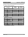
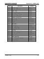
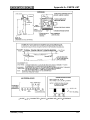
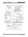
1
645 Russell St.
Batesburg, SC 29006
Service Manual 5865
High Frequency Track Circuits
Installation and Maintenance
December, 1999
© 1999, Union Switch & Signal Inc.
Printed in USA
An ANSALDO Signal Company
Revision Index
Date of Revision
August, 1980
December, 1999
SM5865 (12/99)
i
Table of Contents
SECTION
1.0
1.1
1.2
2.0
2.1
3.0
3.1
3.2
3.3
3.3.1
3.3.2
3.3.3
4.0
TOPIC
PAGE
GENERAL INFORMATION ......................................................................... 1-1
INTRODUCTION ......................................................................................... 1-1
R.A.I.L. TEAM AND TECHNICAL SUPPORT.............................................. 1-2
OPERATION..................................................................................................... 2-1
High Frequency Track Circuit Function ............................................................. 2-1
DESCRIPTION ................................................................................................. 3-1
Transmitter........................................................................................................ 3-1
Receiver............................................................................................................ 3-1
Associated Hardware ........................................................................................ 3-2
Track Connections and Rail Bonds................................................................... 3-2
Receiver Relay.................................................................................................. 3-2
Lightning Protection .......................................................................................... 3-2
APPLICATION AND INSTALLATION DATA ................................................... 4-1
4.1
Frequency Selection ......................................................................................... 4-1
4.2
Track Circuit Connection Arrangements ........................................................... 4-1
4.2.1 General Information .......................................................................................... 4-1
4.2.2 Typical Track Circuit Illustrations ...................................................................... 4-1
4.3
Equipment Mounting Data................................................................................. 4-5
4.4
Tuning Sensitivity Adjustments ......................................................................... 4-6
5.0
FIELD INSPECTION AND SERVICING ........................................................... 5-1
5.1
Test Equipment and Periodic Inspection........................................................... 5-1
5.1.1 Transmitter........................................................................................................ 5-1
5.1.2 Receiver............................................................................................................ 5-1
5.2
Field Servicing .................................................................................................. 5-2
APPENDIX
PARTS LIST........................................................................................A-1
A.1
Transmitter and Receiver Assemblies ......................................................... A-1
A.2
Circuit Boards .............................................................................................. A-1
A.3
General Parts List........................................................................................ A-2
A.4
Auxiliary Tabulation ..................................................................................... A-4
SM5865 (12/99)
i
Table of Contents
LIST OF FIGURES
1-1
1-2
3-1
4-1
4-2
4-3
4-4
4-5A
4-5B
4-6
4-7
4-8
A-1
A-2
A-3A
A-3B
A-4A
A-4B
Physical Layout ........................................................................................... 1-1
Electrical Layout .......................................................................................... 1-1
Diagonal Shunt Installation .......................................................................... 3-3
Single Track Circuit ..................................................................................... 4-2
Dual Circuit with Diagonal Shunt ................................................................. 4-2
Single Switch Track Circuit .......................................................................... 4-3
LAP Switch Track Circuit ............................................................................. 4-3
Short Circuits ............................................................................................... 4-4
Short Circuits ............................................................................................... 4-4
Overlapped Circuits ..................................................................................... 4-5
Mounting Equipment.................................................................................... 4-5
Rail-to-Rail Shunt Connection ..................................................................... 4-8
Wiring Diagram for High Frequency Track Circuits...................................... A-4
Assembly of Equipment for High Frequency Track Circuits ......................... A-5
Transmitter Circuit Diagram and Parts Reference ....................................... A-6
Transmitter Circuit Diagram and Parts Reference ....................................... A-7
Receiver Circuit Diagram and Parts Reference ........................................... A-8
Receiver Circuit Diagram and Parts Reference ........................................... A-9
LIST OF TABLES
4-1
5-1
5-2
ii
Standard Values for Tuning Circuits ............................................................ 4-7
Transmitter Field Servicing .......................................................................... 5-2
Receiver Field Servicing .............................................................................. 5-3
SM5865 (12/99)
Section 1.0 – INTRODUCTION
1.1 GENERAL INFORMATION
The US&S High Frequency Track Circuit is designed to be used where short track
circuits are required, such as in classification yards, to provide switch locking protection.
Insulated joints are not necessary with this circuit.
The equipment is completely transistorized and is designed to operate from 117 volt,
60 Hz power source.
Since the track circuits are short, the condition of the ballast is not critical. More
important is the ability to work in areas where there is rail film, such as normally found in
classification yards. Tests with the high frequency circuits have shown no indication of
failure to shunt when a heavy grease film mixed with dirt was applied to the rails.
Track circuits have been employed with lengths of between 60 and 250 feet, and no
difficulty is foreseen in lengths up to 300 feet.
A typical high frequency track circuit consists of a transmitter, receiver and associated
relay, connected between two (2) rail-to-rail shorts, which define the limits of the track
circuit. The transmitter is connected approximately twenty (20) feet from one short with
capacitors connected within the unit and on the output terminals to tune that section of
the track to the transmitter frequency. The receiver is connected approximately twenty
(20) feet from the other short with capacitors connected within the unit and on the input
terminals to tune that section of the track to the transmitted frequency.
Electrically, this makes the enclosed section of track look like two tuned circuits coupled
in parallel with the inductance of the untuned section of track in series. (See Figures 1-1
and 1-2.)
FIGURE 1-1. PHYSICAL LAYOUT
FIGURE 1-2. ELECTRICAL EQUIVALENT
SM5865 (12/99)
1-1
Section 1.0 - INTRODUCTION
The equipment is contained within a weatherproof case that is pedestal mounted on the
wayside at 3 feet from the nearest rail. Power input, track, and relay output connections
are made to an AAR terminal strip mounted internally. The receiver relay is external and
can be located where convenient, up to several thousand feet away from the receiver.
1.2 R.A.I.L. TEAM AND TECHNICAL SUPPORT
The Rapid Action Information Link (R.A.I.L.) Team is comprised
of a group of experienced product and application engineers
ready to assist and resolve any technical issues concerning any
US&S product.
Any questions regarding the contents of this Service Manual can
be answered by contacting the R.A.I.L. Team toll free at
800-652-7276 or via e-mail: [email protected].
1-2
SM5865 (12/99)
Section 2.0 - OPERATION
2.1 High Frequency Track Circuit Function
The High Frequency Track Circuit functions by applying bursts of high frequency energy
into the tuned section of track from the transistor oscillator and power amplifier that form
the transmitter. The energy is coupled through the rails into the tuned section of track at
the receiver input. These bursts of energy are of approximately two-millisecond
duration, with approximately eight-milliseconds between bursts. The input circuit of the
receiver transformer couples this energy into a bridge rectifier, which converts the high
frequency energy into square pulses of two-millisecond duration with eight-milliseconds
between pulses. When these pulses are of sufficient amplitude to trigger the fail-safe
peak detector, a separate frequency of approximately 220 kHz is generated in the
receiver. This signal is amplified, detected and converted into a D-C control voltage to
energize the relay. As long as the amplitude of the input triggers the peak detector, the
relay will be held energized.
The relay will drop out from failure of input power to either the receiver or transmitter,
from loss of connections to the rails or from normal shunting of the track by a car. This
will de-tune and short either the output of the transmitter or input to the receiver, or both,
depending on the position of the wheels within the limits of the track circuit.
Because of the rail-to-rail shorts, which define the limits of the track circuit, it is virtually
impossible to get interference from adjacent circuits. Also, the receiver input is very
selective with its high “Q” parallel resonant input circuit; and a transmitter of another
frequency can be operated directly across the receiver inputs without causing false
operation.
SM5865 (12/99)
2-1
Section 2.0 - OPERATION
This page is intentionally blank.
2-2
SM5865 (12/99)
Section 3.0 - DESCRIPTION
3.1.
Transmitter
The transmitter consists of:
a printed circuit board containing a rectifier to convert the power supply to DC;
an RF oscillator;
a timing multivibrator, which controls the transmitter ON-OFF duty cycle;
a single-ended Class “B” power amplifier;
a power transformer, which converts the 117 volts, 60 Hz supply voltage to 32
volts; and
a separate board with solder terminals for mounting capacitors to tune the track.
An AAR terminal strip provides for external connections to the track, the supply voltage
and the case ground.
Provisions are included for mounting lightning arresters in installations where they are
required. A complete unit can be furnished with or without arresters.
All of this is contained in a weatherproof box that is mounted near the rails, so that the
track lead to the nearest rail is no longer than three feet. The supply voltage leads enter
the box through the bottom, while the track leads enter through a weatherproof fitting on
the end nearest the rails.
The transmitter output amplifier is capable of driving a minimum ballast impedance of 2
ohms/1000 ft. The timing and “Q” of the track will determine the load impedance seen
by the transmitter with very little effect from the ballast since the track circuit is short.
Typical load impedance of twelve ohms would permit peak output power during the
pulse of approximately fifty watts. The efficiency of the circuit is very high due to Class
“B” operation and low duty cycle.
The available frequencies for operation are 46.5 kHz, 57 kHz, 71. 5 kHz, and 89 kHz.
3.2 Receiver
The receiver consists of:
a printed circuit board containing all the circuitry necessary to convert the R.F.
signal received from the track to a DC voltage (to operate a 400 ohm relay);
a power transformer (to change the 117 volts, 60 Hz supply voltage to 25. 2 volts,
60 Hz); and
a separate board with solder terminals for mounting capacitors to tune the track.
An AAR terminal strip provides for external connections to the track, supply voltage and
relay. Provisions are included for mounting lightning arresters in installations where they
are needed. All of this is contained in a weatherproof box, which is mounted near the
rails so that the track lead to the nearest rail is no longer than three (3) feet. The supply
voltage and relay leads will enter the box through the bottom, while the track leads will
be brought through a weatherproof fitting on the end towards the rails.
SM5865 (12/99)
3-1
Section 3.0 - DESCRIPTION
3.3 ASSOCIATED HARDWARE
3.3.1 Track Connections and Rail Bonds
The track connections, rail bonds, and rail-to-rail shorts must be very securely fastened
and properly located or the track circuit cannot function properly. Any loosening,
breaking or shifting of connections can change the tuning or completely disable the
system.
All track leads should be AWG #6, insulated, stranded wire, or equivalent insulated
bond wire.
These leads should be twisted at least three twists per foot between the nearest rail and
the transmitter or receiver mounting box. The lead to the far rail must be as short as
possible.
The rail-to-rail shorts consist of two leads of the same wire as the track leads and
spaced a minimum of five inches apart with staples driven into the ties. The ends must
be securely bolted or welded to the web of the rails.
All rail bonds must be heavy gauge, railhead-type, either welded or swaged securely
into the rail for best operation. Longer bonds may be used where rail hardware makes it
necessary, but the railhead-type is preferred and should be used whenever possible.
In applications where two track circuits are in series and a sharp transfer from one
circuit to the other is required, a diagonal shunt must be installed in a ten-foot section of
track. This diagonal must be made of three leads equivalent to the track leads. These
may be connected at one point on each rail, but the leads must be spaced a minimum
of five inches apart and stapled to the ties between the rails. The receiver of one circuit
is connected at one end of the diagonal shunt, and the receiver or transmitter of the
other circuit is connected at the other end of the diagonal shunt (See Figure 3-1) for
further information, refer to Section 4.0 Application and Installation Data.
3.3.2 Receiver Relay
The receiver is designed to operate a relay with a 400-ohm coil, typically the PN-150B
(N322500-001) or PN-50B (N292701). The pick-up voltage is normally 5.3 volts DC and
the drop-away 1.9 volts DC. The current at 5.3 volts is only .0132 ampere; therefore, the
relay can be located several thousand feet from the receiver and still be operational.
3.3.3 Lightning Protection
Provision has been included for mounting a Style USG Arrester, N314265, from each
track lead to ground in both the receiver and transmitter. Actual installation of the
arresters is required when the particular track circuit is isolated from others or when it is
the first or last of a number of track circuits along a section of track.
3-2
SM5865 (12/99)
Section 3.0 - DESCRIPTION
These arresters permit a maximum of 300 volts before breakdown. The pedestal that
the equipment is mounted on provides grounding for the arresters. However, in areas
where poor ground conductivity is experienced, conventional ground rods may be used
with the arresters connected to the pedestal, the ground rod or both.
FIGURE 3-1. DIAGONAL SHUNT INSTALLATION
SM5865 (12/99)
3-3
Section 3.0 - DESCRIPTION
This page is intentionally blank.
3-4
SM5865 (12/99)
Section 4.0 - APPLICATION AND INSTALLATION
4.1.
FREQUENCY SELECTION
There are four frequencies available, 46.5, 57, 71.5 and 89 kHz. To assure that two
track circuits operating on the same frequency do not interfere with each other, the
following rules shall be observed.
1.
Do not install track circuits directly parallel to each other on adjacent tracks
unless the operating frequencies are different. Where there are three or more
tracks in parallel, every other track may have the same frequency.
2.
Do not install track circuits of the same frequency along the same track, unless a
track circuit of a different frequency separates them.
3.
Where two track circuits are to be installed with a diagonal rail-to-rail short
between them to provide overlap of the two circuits, only the lowest and highest
frequency available are to be used. This is presently 46.5 kHz for the lowest and
89 kHz for the highest.
4.
In long track circuits, apply the lowest frequency available.
4.2 TRACK CIRCUIT CONNECTION ARRANGEMENTS
4.2.1 General Information
The frequency allotted for each circuit shall be determined from the rules given in
Section 4-1 Frequency Selection.
Railhead bonds shall be used on all rail joints; and all other joints shall be
bonded as short as possible, depending on track hardware conditions.
4.2.2 Typical Track Circuit Illustrations
The following illustrated track circuit arrangements, shown in Figures 4-1 through
4-6 are given as examples that should provide sufficient information for proper
installation of these track connections, as well as any not specifically given.
The letters shown in parenthesis on each illustration indicate the applicable note
from the following list.
(a)
Rail-to-rail short. Consists of two AWG #6 stranded copper insulated wire
or equivalent, separated a minimum of five inches. The wire is stapled to
the tie and securely attached to the web of the rail, either at a common
point connection or at two separate points, while maintaining the five-inch
separation.
(b)
Track leads. The leads to the transmitter and receiver must be twisted
three twists per foot from the nearest rail to the unit housing, and the
distance to the nearest rail must be three feet or less.
SM5865 (12/99)
4-1
Section 4.0 - APPLICATION AND INSTALLATION
(c)
Where presence detectors are used, the detector “loop” must be located
between the transmitter and receiver rail connections as shown. Under no
circumstances may part of the “loop” be within a tuned section.
(d)
The diagonal shunt (see Figure 3-1).
(e)
Switch bonding. Bonding is necessary around heel blocks and between
rails behind the heel block.
(f)
Switch rail-to-rail shorts. The rail-to-rail shorts must be between the “frog”
and rail connections of transmitter or receiver.
(g)
Switch track leads. The rail connections for transmitter or receiver shall be
made to the fixed rail.
(h)
Shunt zone. Maximum variation of shunting point will fall between the
limits shown.
FIGURE 4-1. SINGLE TRACK CIRCUIT
FIGURE 4-2. DUAL CIRCUIT WITH DIAGONAL SHUNT
4-2
SM5865 (12/99)
Section 4.0 - APPLICATION AND INSTALLATION
FIGURE 4-3. SINGLE SWITCH TRACK CIRCUIT
FIGURE 4-4. LAP SWITCH TRACK CIRCUIT
SM5865 (12/99)
4-3
Section 4.0 - APPLICATION AND INSTALLATION
FIGURE 4-5A. SHORT CIRCUITS
FIGURE 4-5B. SHORT CIRCUITS
Where space requirements necessitate, such as close-coupled switches (shown
dotted), two circuits may be “overlapped” as shown. Each circuit will shunt
independently. A1 need not equal A2, although all dimensions are subject to the length
limitations as shown in Figure 4-5A. The transmitters can be staggered, if required, as
shown in Figure 4-5B.
4-4
SM5865 (12/99)
Section 4.0 - APPLICATION AND INSTALLATION
FIGURE 4-6. OVERLAPPED CIRCUITS
4.3 EQUIPMENT MOUNTING DATA
A transmitter or receiver basic housing consists of a cast iron box, M374986, with cover
M347723, and a pedestal, M224650, which are shipped separately. The unit is mounted
near the rails with the pedestal buried in the ground, so that the bottom of the box is
two to four inches above the ground. The length of the track lead to the nearest rail shall
be no longer than three feet (see Figure 4-7).
The 117 volt, 60 Hz power lead and the relay control wires are brought through a
special opening in the pedestal and through the bottom of the box. The track leads are
brought through the end of the box nearest the rails. The terminals on the AAR terminal
strip are identified for convenience in wiring all external connections. A second soldertype terminal strip is provided to mount the tuning capacitors required to resonate that
section of track between the track lead connections and the rail-to-rail short.
FIGURE 4-7. MOUNTING EQUIPMENT
SM5865 (12/99)
4-5
Section 4.0 - APPLICATION AND INSTALLATION
4.4 TUNING AND SENSITIVITY ADJUSTMENTS
Proper tuning of the track is most easily accomplished by using an oscilloscope and a
decade capacitor box. A fixed capacitor has been installed on the track lead terminal
strip. Additional capacitors must be installed during installation to fine-tune the track.
These capacitors will be in parallel with the fixed capacitor. Before any AC power is
connected to the transmitter, connect a decade capacity box to the track lead and set it
to 1 MFD to tune the track. Then turn on the power and reduce the decade box setting
until a maximum signal is obtained across the terminal as discussed below. After tuning,
fixed capacitors equal to the final setting of the decade box are then installed.
The range of capacitance required to tune a track circuit will vary from approximately
.33 MFD for the highest frequency to approximately 2.0 MFD for the lowest frequency,
depending on the installation arrangement.
In most cases, the track circuit will be short enough that it will be best to tune the
transmitter and receiver simultaneously, or at least back and forth, until the maximum
signal is obtained.
To tune the transmitter, it is best to connect an oscilloscope at the rail connections and
the decade box at the track connections inside the transmitter enclosure.
To tune the receiver, it is best to connect both the oscilloscope and decade box at the
track connections inside the receiver enclosure. Temporarily connect a non-inductive
10-ohm, 50-watt resistor in series with one lead of the transmitter.
Adjust the decade capacitor boxes in equal steps at both the transmitter and receiver
until resonance is obtained in both circuits. This is indicated by obtaining a maximum
signal on the scope.
Note
The capacitance at the receiver and transmitter may differ 10 to 20 percent at
resonance in a straight track circuit, and nearly 100 percent when one is on
straight track and the other at a diagonal shunt. Remove the resistor and
recheck the tuning before proceeding.
The amplitude of the signal at the transmitter may be between 50 and 80 volts peak-topeak, while at the receiver it may be between 50 and 150 volts peak-to-peak.
When the capacitance value has been determined, remove the decade box, and solder
fixed capacitors to the terminal board provided in each enclosure, equal to the decade
setting. In every case, choose capacitors that are equal to or slightly less than the
decade setting, never larger.
4-6
SM5865 (12/99)
Section 4.0 - APPLICATION AND INSTALLATION
The following standard values should provide enough combinations to satisfactorily tune
all circuits.
TABLE 4-1 STANDARD VALUES FOR TUNING CIRCUITS
.015 MFD
±10%
200 volt
J709144-0076
.047 MFD
±10%
200 volt
J709144-0075
.10 MFD
±10%
200 volt
J709144-0083
.15 MFD
±10%
200 volt
J709144-0082
.33 MFD
±10%
200 volt
J709144-0081
.47 MFD
±10%
200 volt
J709144-0080
.56 MFD
±10%
200 volt
J709144-0079
.68 MFD
±10%
200 volt
J709144-0078
±10%
200 volt
J709144-0077
1.0 MFD
NOTES
1.
On track circuits longer than 100’, tuning should be done by first
shorting the receiver track terminals and then adjusting the transmitter
decade box for maximum signal. Finally remove the short from the
receiver and tune the receiver end.
2.
For diagonal shunt arrangements with two circuits adjacent to each
other, tune the low frequency unit first with the high frequency circuit
open circuited, with the low frequency circuit intact and tuned.
After the tuning capacitors have been installed, proceed with the sensitivity adjustment
as follows:
(a)
Connect an oscilloscope across the receiver input terminal.
(b)
Connect a DC voltmeter (set on the 10-volt range) across the relay
terminals. (A 400-ohm relay or resistor should be connected to the
terminals for proper loading.)
(c)
Connect a rail-to-rail shunt on the rail midway between the receiver track
connections and the receiver rail-to-rail short. The rail-to-rail shunt wire
should be at least #6 AWG and not longer than seven feet. See
Figure 4.8.
SM5865 (12/99)
4-7
Section 4.0 - APPLICATION AND INSTALLATION
FIGURE 4.8 RAIL-TO-RAIL SHUNT CONNECTION
Note:
The location of the shunt in the center of the shunt zone as shown in
Figure 4.8 will satisfy most applications. However, in congested areas
where there is an abundance of steel traversing between the rails in the
shunt zone, a shift of four or five feet of the shunt location closer to the
receiver might be necessary to properly adjust the track circuit.
(d)
Set the sensitivity control on the receiver for a reading of 1.9 ± .1 volt DC
on the multimeter.
(e)
Loosen the south end of the rail-to-rail shunt and connect to point “a.”
Verify that the voltage level increases.
(f)
Move the south end of the rail-to-rail shunt from point “a” to point “b.”
Verify that the voltage level decreases.
(g)
Remove the shunt. The voltage should rise to 5.8 ± .3 volts DC.
The circuit is now ready for operation.
4-8
SM5865 (12/99)
Section 5.0 - FIELD INSPECTION AND SERVICING
Regularly scheduled maintenance for any type of equipment is the best way to assure
reliable operation for a long period of time. Therefore, the following information is given
to assist in establishing some form of periodic inspection and test.
5.1 TEST EQUIPMENT AND PERIODIC INSPECTION
For a quick simple check of the equipment’s general condition, all that is needed is an
analyzer similar to a Simpson Model 260. The periodic test should consist of the
following checks:
5.1.1 Transmitter
Visibly inspect for moisture damage and component discoloration from overheating.
Refer to Figure A-3 for transmitter circuit and parts reference.
Note the following voltages:
(a)
Line voltage, 117 volts ± 10%, 60 Hz.
(b)
Power input to board, 32 volts ± 10% 60 Hz.
(c)
DC across C8, 40 volts ± 10%
(d)
DC across C1, 26 volts ± 10%
*(e)
Output, 2.5 volts RMS minimum
* This low voltage reading is the result of a 20% duty cycle, pulse operation.
Continuous operation of the transmitter output would give a reading
approximately five times as high.
5.1.2 RECEIVER
Visibly inspect for moisture damage and component discoloration from overheating.
Refer to Figure A-4 for receiver circuit and parts reference.
(a)
Line voltage, 117 volts ± 10%, 60 Hz.
(b)
Power input to board, 25.2 volts ± 10% 60 Hz.
(c)
DC across C16, 36 volts ± 10%.
(d)
Relay voltage, 5.8 volts DC, ± .3 volts.
*(e)
Input from track, 2.5 volts minimum.
* This is the RMS reading of the 20% duty cycle of the transmitted pulse. If the
reading is between 12 and 20 volts RMS, the transmitter is in continuous
transmission instead of pulse.
SM5865 (12/99)
5-1
Section 5.0 - FIELD INSPECTION AND SERVICING
The historical record of several inspections provides a means of determining when a
unit is about to fail, because a consistently repeated reading establishes the proper
operating reference. Therefore, when a particular reading begins to change from one
inspection to another, this can be interpreted as an approaching failure in that unit.
5.2 FIELD SERVICING
In the event that actual failure occurs, the voltage checks of the periodic inspection will
provide enough information to determine where the failure has occurred. Interpretation
of readings is shown on the following troubleshooting tables.
TABLE 5-1. TRANSMITTER FIELD SERVICING
INDICATION
CORRECTIVE ACTION
1.
No line voltage
Check power distribution system and cabling.
2.
Low line voltage when
circuit is connected.
Check transformer for shorted turns, or shorts on
the printed circuit board. Replace transformer or
printed circuit board.
3.
Low DC voltages.
(a) Check tracks and track leads for shorts.
(b) Check to see that tuning capacitors are not
broken loose or defective. (Detuned circuit
loads DC supply)
(c) Replace printed circuit board if (a) and (b) are
good.
4.
Low output.
Same as step three (3).
5.
High output.
Replace printed circuit board as timing multivibrator
circuit is defective, allowing transmitter to operate
continuously.
5-2
SM5865 (12/99)
Section 4.0 - APPLICATION AND INSTALLATION
TABLE 5-2. RECEIVER FIELD SERVICING
INDICATION
CORRECTIVE ACTION
1.
No line voltage
Check power distribution system and cabling.
2.
Low line voltage when
circuit is connected.
Check transformer for shorted turns or shorts on the
printed circuit board. Replace defective part.
3.
Low DC voltage
If line voltage is good, check for a short circuit in
output to relay or low relay voltage. Replace board.
4.
No relay voltage
Check for signal on input terminals. If input from track
is low or too high, trouble is in track or transmitter.
NOTE
If input RMS voltage is greater than 12 V RMS, the
transmitter is operating continuously and the receiver
cannot respond to a continuous input.
5.
No input
SM5865 (12/99)
Check all track leads and rail connections for opens
or shorts. Check transmitter output. Repair track
leads or replace transmitter as required.
5-3
Section 5.0 - FIELD INSPECTION AND SERVICING
This page is intentionally blank.
5-4
SM5865 (12/99)
Appendix A – PARTS LIST
The parts list that follows is a tabulation of the parts that may be necessary to maintain
this equipment. These parts may be ordered directly from Union Switch & Signal Inc.
A.1 Transmitter and Receiver Assemblies
Part No.
Complete
Description
Part No.
less Pedestal
Transmitter Assembly, with Arrestor
46.5
57
71.5
89
kHz
kHz
kHz
kHz
Transmitter
Transmitter
Transmitter
Transmitter
*
*
*
*
X451147-0135
X451147-0139
X451147-0143
X451147-0147
N451147-0103
N451147-0107
N451147-0111
N451147-0115
X451147-0133
X451147-0137
X451147-0141
X451147-0145
N451147-0101
N451147-0105
N451147-0109
N451147-0113
Receiver Assembly, with Arrestor
46.5
57
71.5
89
kHz
kHz
kHz
kHz
Receiver
Receiver
Receiver
Receiver
*
*
*
*
A.2 Circuit Boards
Circuit Boards for Transmitters
46.5
57
71.5
89
kHz
kHz
kHz
kHz
Transmitter
Transmitter
Transmitter
Transmitter
N451055-1201
N451055-1202
N451055-1203
N451055-1204
Circuit Boards for Receivers
46.5
57
71.5
89
kHz
kHz
kHz
kHz
Receiver
Receiver
Receiver
Receiver
N451055-1301
N451055-1302
N451055-1303
N451055-1304
* Complete Assemblies include Pedestal
SM5865 (12/99)
A-1
Appendix A – PARTS LIST
A.3 General Parts List
Item #
5
10
15
20
25
30
35
40
45
50
55
60
65
70
75
80
85
90
95
100
105
110
115
120
125
130
135
140
145
150
155
160
165
170
175
180
185
190
195
200
205
A-2
Description
Box
Cover
Elbow, 1st St M I Galv
Gsk Nprn Spg ½ x ½
Not used
SC 3/8 x 1-¼ Set Cad P
Nut, 3/8 Hex Stl Cad P
Plate, Mounting
SC ¼ - 20 x 7/8 Fil Stp
Washer, ¼ M LK S TP
Block, Terminal, 7 way
Block, Terminal 3 way
Washer
Nut
Nut
Arrester
Connector, Term
Chassis
Transformer
Board, Pri-Cir
Board, Term
Spacer
Nut-6-31 Hex Stl Tr
Bushing 2 ½ x 2 Red
Bushing, 2 x 1 ¼ Red
Nut, Lock
Plastic Cap Plug
Plastic Cap Plug
Elbow, 1 ¼ St M I Galv
Pipe, 1 ¼ Galv
Nut, ¼ - 20 Hex Stl Tp
SC 4-40x 5/16 bind Stl Tp
Washer 4 M Lk S Tp
Washer, 4 Plate S Tp
SC 8-32 x ½ Bind Stl Tp
Washer 8 M Lk S Tp
Washer 8 plate S Tp
Spacer
SC 8-23 x 3/8 Bind Stl Tp
SC 2 x ¼ Rd Type U Drive Sc Tp
Nut 8-32 Hex Stl Tp
Part No.
M374986
M347723
J32485
A690937
Not used
J50577
J48009
M451148-0101
J52202
J47775
M225586
M109154
J47818
M29103
M29101
N451552-0101
M47290
See Aux Tab
See Aux Tab
See Aux Tab
J776611
J772336
J048148
J032088
J32054
M373656
J703517
J703516
J32486
M437182
J48002
J50996
J47765
J47640
J50992
J47681
J47745
M485696
J507235
J52648
J48166
SM5865 (12/99)
Appendix A– PARTS LIST
Item #
210
215
220
225
230
235
240
245
250
255
260
265
270
275
280
285
290
300
305
310
315
320
325
330
335
340
345
350
355
360
365
370
SM5865 (12/99)
Description
Plate, Name
Receptacle, DX
SC 6-32 x 3/8 Pan Stp
Pipe, 1” Galv
Screen
Bushing, 1” Conduit
Bolt, ½ - 13 x 3-1/2 Hex
Nut, ½ Hex X Jam Cad P
Nut, ½ Hex Stl Cap P.
Washer ½ Plat Stl Cad P
Washer # 6 Lock Stl
Tag, B x 110
Tag, N x 110
Rag, Relay +
Tag, Relay Tag, Track 1
Tag, Gnd
Term, #6 Amp
Term. #12 – ¼ amp
Wire #18 Flex (Bk)
Wire, #18, Flex (W)
Grommet
Scr. ¼ - 20 x 358 Pnh Stl
Nut, Insulated
SC 4-40 x ¼ Flat Stl Tp
Tag, Track E
Term # 10 Amr
Initial Tuning Cap
Wire, #20 Bare Copper
Wire, #20, PVC Grn M-258-30
Tubing
Wshr – 10 Flt Stl
Part No.
M451425-9701
J72030
J507262
M26503
M435695
J69677
J046563
J48016
J48013
J47503
J047662
J75510-0689
J75510-0080
J75510-1157
J75510-1158
J75510-1169
J75510-0566
J730239
J730041
A45665-0000
A45665-0009
J751238
J507263
J48300
J521070
J75510-1170
J730048
See Tab
A043180
A045505-0004
A774201
J475077
A-3
Appendix A – PARTS LIST
N451147
Circuit Bd
Transformer
F451055
SH
C8605
Initial Tuning
Capacitor
Mfd
Freq kHz
Group
Chassis
Suffix
RCVR or
XMTR
Housing
A.4 Auxiliary Tabulation
SH
-0101
-0117
1
46.5
N451055-1301
13
J730805
--
J709144-0178
0.68
-0103
-0119
3
46.5
N451055-1201
12
N435551
68
J709144-0078
0.68
-0105
-0121
1
57
N451055-1302
13
J730805
--
J709144-0078
0.60
-0107
-0123
3
57
N451055-1202
12
N435551
68
J709144-0078
0.68
-0109
-0188
1
71.5
N451055-1303
13
J730805
--
J709144-0081
0.33
-0111
-0127
3
71.5
N451055-1203
12
N435551
68
J709144-0081
0.33
-0113
-0189
1
89
N451055-1304
13
J730805
--
J709144-0082
0.15
-0015
-0131
3
89
N451055-1204
12
N435551
68
J709144-0082
0.15
FIGURE A-1. W IRING DIAGRAM FOR HIGH FREQUENCY TRACK CIRCUITS
A-4
SM5865 (12/99)
Appendix A– PARTS LIST
FIGURE A-2. ASSEMBLY OF EQUIPMENT FOR HIGH FREQUENCY TRACK CIRCUITS
SM5865 (12/99)
A-5
Appendix A – PARTS LIST
FIGURE A-3A. TRANSMITTER CIRCUIT DIAGRAM AND PARTS REFERENCE
A-6
SM5865 (12/99)
Appendix A– PARTS LIST
FIGURE A-3B. TRANSMITTER CIRCUIT DIAGRAM AND PARTS REFERENCE
SM5865 (12/99)
A-7
Appendix A – PARTS LIST
FIGURE A-4A. RECEIVER CIRCUIT DIAGRAM AND PARTS REFERENCE
A-8
SM5865 (12/99)
Appendix A– PARTS LIST
FIGURE A-4B. RECEIVER CIRCUIT DIAGRAM AND PARTS REFERENCE
SM5865 (12/99)
A-9
Appendix A – PARTS LIST
This page is intentionally blank.
A-10
SM5865 (12/99)