1
(UN!ON SWiTCH & SIGNALjjffil
SERVICE MANUAL 6237 A
A member of Iha ANSALCO Group
5800 ~rporate Drive, Pittsburgh, PA 15237
'
•
•
~
...
•
•
'·
\
J
•
•
•
•
1'
•
•
~
•
•
•
'
....
•
•
•
•
t "'
t
•
Installation, Operation, Field and Shop Maintenance
Oual-Frequency
TRU-11 Code Reset Module
N451206-0301
,:.;;_,.~· .
Augu·it, 1393
·,,,... .,,~,.;:
A·a/9~·3012
?&C MAC·ll 6237A
XFVRIGHT 1993, UNION SWITCH & S;GNAL :NC.
PRINTED ;N USA
....
·. ~-~:~,....,..
..
;.,
'
.
;-\',,;.
.
.
ANS ALDO
Trascorti
REV!S::Z:CN INDEX
Revised pages of this manual are listed by page number a~d date of re~ision.
CCNE~lTS
GENERAL :NFORMATICN
!!'ITRODUCT:ON
S?ECIF!C.=I.TIONS
I
1.1
l.2
II
2.1
2.2
!!!
3.1
3.2
IV
4.1
4.2
4.2.l
4.2.2
4.3
4.3.l
4.3.2
4.4
4.4.l
4.4.2
4.4.2.l
4.4.2.2
4.4.3
4.4.3.l
4.4.3.2
APPENDIX A
A.l
A.2
1-:
:!.-1
1-:!.
INSTALLATION
EQUIPMENT RACK MOUNT:NG
SHELF MOUNT:NG
2-:!.
FUNCTIONAL DESCRIPTICN
GENERAL
DETAILED
3-1
3-1
3-1
~.AINTENANCE AND TEST PROCEDURES
GENERAL
FIELD CHECKS
Recommended Test Equipment
Procedure
OPERATIONAL SHOP TESTS
Recommended Test Equipment and Set-Up
Test Procedure
COMPONENT SHOP.TESTS
General
Series-Tuned Circuits Test
Recommended Test Equipment and Set-Up
Test Procedure
Transformer Test
Recommended Test Equipment and Set-Up
Test Procedure
4-1
4-1
4-1
4-1
4-1
?ARTS LIST
COMPLETE ASSE~.BLY N45:206-030l
RESET PCB N451807-7601
2-1
2-:.
4-2
4-2
4-4
4-6
4-6
4-6
4-6
4-8
4-10
4-10
4-11
A-1
A-4
ILLUS:'RAT!CNS
Fiqu't""~
2-:
4-4.
4-5.
In~tallation Diagram
System Application Diagram
Reset Mcdule Schematic Diag=am
Operaticnal Shop Test Set-~p
Series 7~ned Circuit Test Sec-~p
Series-:~ned Test - Oscilloscope ~avefo=:::1
Transfc=er Test Set-Up
T=ansfo=e.:: 7es-:: - Oscil.!.cs::o,::e ;'ia•,e::o=:::1
..\-:.
u~it Cc=plece Assembly
.=>..-:..
A-2.
~eset ?C3 Component ~ayo~t
A-S
2-l.
3-1.
3-2.
4-1
4-2.
4-3.
3-2
3-4
4-3
4-7
4-9
4-:. ')
4-·.
SEC':':;'.ON I
GE~ERAL :Z:)lFORMATION
1.1
INTRODUCTION
This :nanual describes the operation, i~stallation and maintenance of the DualFrequency TRU-II Code Reset Module, US&S part no. N4512C6-0301. The module is
desig~ed for use with a TRU-II Track Resonant Unit (re:er to service manual SM6236) when the latter is applied in code overlay applications. Ween a track
circuit shunt is rel~ased in a TRU-II cede overlay arrangement, the module
provides the release of the "V" (frequency control relay), allowing t~e TRU-II to
reset with steady energy track feed. The module is a plug-in package designed for
mounting on a standard relay rack configuration using a special mounting plate.
The Dual Frequency TRU-II Code Reset Module differs from the earlier Code Reset
Module (part number N451206-02XX) in the following respects:
1.2
A.
Operates at a second carrier frequency of 250 Hz
B.
Provides reset capability for additional standard code rates of 270
and 420
C.
Does not function as a vital device (refer to section 3.1)
D.
Replaces al.l -02XX models with a single unit
SPECIFICATIONS
=
2-3/8",
Dimensions:
H
Weight:
5 lbs.
Mounting:
Standard relay rack
Local Voltage:
110 or 120V ac ±10%@ 50, 60, 91.67 or 100 Hz
Local Current:
20 ~-
Track Voltage:
10.0 co 30.0V ac +10%@ 91.67 and 100 Hz
Track Current:
9
8", W
mA ~
D
9-:./2"
9V ac (e,:<:lrgized scace)
Dielect.:::ic Breakdown 'lo.:..tage: 3, OO'JV ac :sMS, 60 nz fer one
A:l ter~inals to ciassis
Propulsion Power:
DC ::::, 60 nz ac
Frequency Immunity:
Rase~ wi.:.l not ene~gize:
25 Hz, ?ropu!sicn, :SO? ac
60 Hz, propulsion, !SQV ac
250 Hz,
s::..g!"!a.:.,
::s-:i'
ac
Maximum Code Rate:
42C code
Minimum Coder "On" and
"Off" Time:
381
Operating Temperature Range:
SE:C:'!ON II
INS':ALLA'!'ION
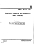
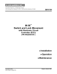
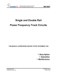
(See Figure 2-1)
MARZ CERT.Am S:CGNAL AND OPERATING l?OWER TO THE DU.ALi'REQOE."'lCY TRU-IJ: CODE RESE':! MCCOLE RE."f.A!NS OFF UN'l:i:L A:.L
INSTALLATJ:ON PROCEDURES ARE COMPLETZ, O'l'HERW:CSE l?ERSONAL
INJURY MAY RESULT.
,,,
2.l
EQUil?MENT RACK MOUNTING
NOTES
The Dual Frequency TRU-II Code Reset Module is a7ailable
with rack mounting plate included (refer to Appendix A).
The TRU-II Track Resonant Unit and reset module must be
mounted side-by-side.
l.
If mounting the module on a US&S equipment rack, bolt the base plate in
position.
2.
Solder local signal lines (ll0-l20V ac) to socket terminals land 2 on the
module.
3.
Solder track lines (lOV ac) to socket terminals 5 and 6 on the module.
4.
Solder external signal wires for "V" relay control to socket terminals 3 and
4 on the module.
2.2
SHELF MOUNTING
When shelf mounting the TRU-II system, inscall a mini-rack with the required
combination of track resonant unit, reset ~odule, track relay and repeater relay.
This rack has a resistor unit terminal block mounted ln place next to the terminal
strips.
623-:'.:..,
DUAL-FREQUENCY
TRU-11 CODE RESET MODULE
(REAR VIEW/NOT TO SCALE)
"'~
....
~
'
0
0
It ~
"V" RELAY
CONTROL*
n
u
LOCAL
SIGNAL
110-120\/ AC*
n
2 u
34 }I
Ii 56
n
TRACK
10\/ AC*
u
a a
78
\. 0 JO
7- 5/16"
v
NOT USED
*VIA RACK
CONNECTOR
l
,~
.... ~
I
'3237A, ;; . 2-2
'
SEC':'Z:ON I!!
FUNCTIONAL DESCRIPTION
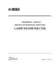
(See :igure 3-1)
3.1
GE~RAL (See Figure 3-1)
The Dual-Frequency TRU-Z:! Code Reset Module is designed to take its signal input
from the tracks in parallel with the TRU-!I Track Resonant Unit. The local input
is only used for internal power. Track relay no. 1 back contact is connected in
series with the reset module input in order to disconnect the source during steady
energy track conditions. When a train shunts the nor:nally steady energy track
circuit, the no. 2 track :relay back contact connects the Bl2 scu:rce to the "V"
relay by way of the RRl? back contact and traffic control circuits.
The "V" relay connects the source (100 Hz and 250 Hz coded energy) to the track
input. When the train vacates the track circuit, the track system must be reset
to the steady energy mode. The reset is accomplished by the reset module which,
aft.er several 100 Hz or 91.67 Hz code cycles, picks up the RRP relay. The "V"
relay stick circuit is released and the source is switched back to steady energy,
permitting the TRU-!I to pick up.
NOTE
The Dual-Frequency TRU-II Code Reset Module is not considered "vital" since resett.!.ng code to steady energy is
not a vital function. The ':'RU-I! Track Resonant Unit
provides the required steady.energy pick-up.
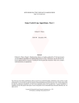
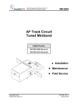
3.2
DETAILED (See Figure 3-2)
The Dual-Frequency TRU-II Code Reset Module accepts 91.67 and 100 Hz input signals
from the W-400 track t:ransfor.r~r at pins 6 and 7. The nominal input signal level
is about lOV ac RMS. A series-tuned fi~ter, consisting of C4 and L23 is connected
in series with the input to transformer T2. A second series-tuned circuit,
consisti.~g of C3 and Ll, is connected to the secondary of transformer T2 in series
with the PC board lead. Under minimum i~put signal of 9V ac RMS, transformer T2
operates as a normal transformer device. When the input inc:reases above this
minimum level, T2 begins to satu:rate, thus limiting the amplitude of the signal.
The C3/Ll filter tunes out the harmont~e created by the saturable transformer
action.
In addi::ion to i::=:,viding ampli::.ude lim.!.ting fo= i:1-band signals (91. 67 and 100
Hz), T2 also provides amplitude limiting for 25 H= and 60 Hz propulsion
=requenc.!.es. The a.~pli~ude limiting level at 60 Hz is about 60% of the 100 Hz
limiting level, while the limiting leve: at 25 H= is about 25% of the 100 Hz
li."Iliting level. The 250 Hz s.!.gnal frecr~ency is also limited by the combination of
::lte:rs and saturable transfor:r.er. The ~wo series-tuned ci==ui~s are scaggertuned to ?rovide a wide bandwidth for d~al f=eC"~e:1cv and high code rate ope:ration.
6237 ..·'.l., :=>.
------~~---------~
I
I
I
I
I
I
I
I
--------1
I
I
I
I
I
I
I
I
I
I
I
I
I
.:t ______ _--------------- --------
....-~.
I
I
I
·-----------~--~
r------------ ------------------
--------1
I
I
I
I
I
I
I
I
I
I
I
~s
X
::i:: cc
N
I
I
I
xZ
I
I
I
I
I
I
I
N
::i::
0
0
:..-1
-,
Li
x
Cl:l
-
-
•
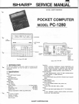
?.:.gure 3-:.
Syst:em ,l.pp.:..:.c3.:.:.::-: :::).:.ag::::a:n
,5:31~.. ,
~
- ..,
· .;-~
-
-
l
~n
11
The filters-t=ansformer combination output signal is connected co terminals 1 and
2 of t~e PC board, where it is full-wave rectifi~d ,ia diodes 01, D2, 03 and 04.
DC output pulses charge capacitor C2 (4,700 uF) through steering diode OS.
Resistor R4 (27K) provides a high impedance discharge path for C2. The output of
the full-wave rectifier also charge capacitor Cl (47 uF) via the back contact of
mercurf-wetted reed relay Kl. Capacitor Cl has a series-connected 685 chm relay
coil, resistor R2 and parallel combination of RS ar.d R6 as a fi~ed, relatively
fast discharge path.
When Sl.67 or 100 Hz code pulses are applied, several seconds are required before
relay K: can pick up, due to the charge time of capacitor C2. When Kl picks up,
Cl provides the relay coil feed over the ccntact t=ansfer time. When the Kl front
contact is made, the relay feed circuit has steering diode 07 and an additional
resistor (Rl) connected in series with its coil. This action increases the reset
module's input impedance to about lK oh.~. The Kl relay remains energized since
the release voltage level is considerably below the pick-up voltage.
Relay :K2 is a power relay repeater cf Kl. It is powered by the local llSV ac,
91.67 or 100 Hz input to PC board terminals 5 and 6. Transformer Tl, in
conjunction with diodes 08 and 09, make up and unfiltered l2v de power source for
the relay. Resistor R3 is a 680 ohm device. The output f=om this de supply is
fed through the front contact of Kl to the K2 repeate= relay. Diode 06 is a relay
coil snub.
PC boa=d resistors Rl and R2 are shown as TBD (to be determined) for adjustment
purposes due to variations in manufacturing specifications for Kl. Ther.nistor RS
and parallel resistor R6 are for relay temperature compensation.
3i; ~
@)
BLK.
BRN,
z
C4
0
h]
I'·
<Q
I~
rt
(I)
nt
z
(ii;
L2
SUPPL! ED
WITII L2
r
r
I
~.)
6
OJ
w
o.
0
)>
0
BLK.
Q
0
5
0
A •
~ ~
GRN.
,,..........
B
}..
:u
r
lll
c
@
en
:n
•14 PVC
11•
'"w
,.,ID
:...
:c{
()
n.
~)
~1
'O
,.,
r
r:
1(~
6
-I
.,.mm
-I
0
(,)
~,
()
'tl
(IJ
:n
:Jn,
("I
I'·
n
lJ
t•·
Ill
<Q
11
Ill
:3
4
:.u
I
:.,·
WHT
,....,
r J-•
Y\_
I
I@
K2
-I
(/)
cen
_-I
<,)
m
0
:::!
'-"
@----/
WIH
•14 PVC
08
SL T.
I @)
0
2
RI
+
)>
Kl
I
OT~
:
I
I
Kl
0
•I
I
I
I
I•
I
z
~
:...
0
PUIG
@
y.
I
r
M! l
:
(rLs
r. c. BOARD@
:
·----------------------------------------------------~
1.:,111f ~l
ALL WI RE •20 PVC UNLESS
OTHERWISE SPECIFIED
R3S
I
SEC':':::ON IV
AN:) TEST i?RCCEDURES
MADlTENANCE
4.l
GENERAL
Initial checks of the Dual Freq~ency TRC-!I Code Reset Module consist of observing
the track relay pick-up during code reset. A module suspected of being defective
should be replaced with one known to be in working order. If a module is found to
be defective, it should be given t~e shop troubleshooting and repair procedures in
section 4.3, or returned to us~s for repair or replacement. Call l-800-652-7276
for factory service information. No attempt should be made to repair the module
in the field.
EXTREME
~
SHOULD BE E.."<ERCISED DURING "POWER
ON" TESTS OF THE DUAL-FREQUENCY TRU-II CODE
RESET MODULE.
CONTACT WITH TlmMJ:NALS MAY
RESULT IN PERSONAL INJURY.
4.2
FIELD CHECKS
Since the reset module is always used with TRU-II (code overlay applications), its
operation can be verified as part of the TRU-II system field check.
4.2.1
Recommended Test Equipment
Dgy~ce
Multi.meter (qty= l l :
20,000 ohm/vol~ (e.g. Simpson 260 or
equi ·,1alent)
4.2.2
,... '
Procedure
·~
l.
Check that the reset module and associated equi~ment a~e propP.rly i~stalled,
including condition and tightness of all tez::ninal connections.
2.
Measure voltage across reset module input socket ter~inals 1 and 2. Voltage
should alwa:.r-s be steady energy in the 110 t·:i 120V ac RMS range (approx.)
3.
To test the reset module itsel:, s~unt its associated track circuit. At
this ti.me the track feed should s~i=t from steady energy to a coded energy
mode. Cn release cf the s~~~t, ~~e t=ack =elay should e~e=gize a=~er a 6 ~:,
10 second delay.
4.3
OPER.a.T!ONAL SHOP TESTS
NOT~
The shop tests given in this section must be perfor~ed
on all Oua!-F=equency TRU-!: Code Reset Modules suspected
of having an internal fault, before these units can be
returned to service.
4.3.l
Recommended ~est Equipment and Sec-Up
Pevic:
0
Oscillator (qty
l) :
Wavecek Model 146
Oscillator (qty
l) :
Wavetek Model 115
Macintosh Model 2100
Amplifier (qty • l):
Frequency Meter (qty
l) :
Hewlett Packard 5300 Measuring System
F=equency Counter {qty= l):
Hewlett Packard 5307A Counte=
Digital Multimeter (qty= l):
Fluke 8000A
Track Transfor.ner (qty= l):
US&S W-400 (pa=t no. N451428-0l04)
Reed Relay (qty= l):
24 volt, Clare JHG.:MSllllTCO or US&S part no.
J726153-0067
Diodes {qty= 2):
1N4C04
Toggle Switch (qty
1):
S.P.S.T.
Resistor (qty= l):
lK ohm, 25 watt
Decade Resistor Boxes (qty= 2):
±3%, Cornell Dubl~e=
Control Transfor.ner (qty= l):
24 ·.1olt
Light Bulb with Base (qty= l):
24 "J'Olt
Breakdown Voltage ~ester:
Hig!:pot C'ur:.ior
Sae F~gure 4-1 for
~~a
se~ up o= th~s
~=s~ equ~pmenc.
"Or equivalent
oL..;1.-.,
::"·
.;-2
FREQ.
METER
MULTIMETER
~
8 1
AMP.
osc
iP
W-400
TRAN SF.
1
146
4
COM.
2P
1N4004
,,
....
osc
.....
2
115
1N4004
GNO
- I
-1
-
+
I
CODE
RELAY
I
I
I
I
I
I
I
I
I
+:
•
I
STEADY
CODE
•
JI
MODE
SWITCH
1K, 25W
OE CADE
RESI STOR
.. "
'.I • .11
-
-
111
~
I >-
>--
6
fO\
%
5
24V TEST
LAMP
4
~:NSFORMER
3
2
115 VAC
POWE~
•I
•
.-
~-.;.
CODE
RESET
;viODULE
R1
DE CADE
RESI STOR
·3
R2
4.3.2
~est P=ocedure
NCTE
This procedure makes re:e=ence to two di::erent versions
of the reset module internal PC3:
Rev. 1 or Rev 2 and
above ("Rev. 2+"). Make note of the revision number on
the board before conduc~ing these tests.
l.
Verification
Ooeration
Connect the reset module into the
test circuit as shown in Figure
4-1.
1.
Notes: Make sure the reset module
and the code relay are in the
upright position. Decade resistors
Rl and R2 only apply to Rev. 2+
l?CBs.
Nota: Steps lA through lK are for
the Rev. 2+ PCS on1y.
lA.
Set the MODE switch to steady.
lA.
lB.
Adjust the amplifier so that Vl
reads 0.00 Vac RMS.
lB.
lC.
Set oscillator no. 1 to 100 Hz and
oscillator no. 2 to 7 Hz (420
code).
lC.
10.
Set decade resistor Rl to 510 ohms
and decade resistor R2 to 100 ohms.
10.
lE.
Adjust the amplifier output so that
multimeter Vl reads 8.4V ac RMS.
lE.
lF.
Adjust decade resistor R2 to a
value that allows the internal
power relay to pick up at t~e 8.4V
ac input level.
lF.
lG.
Remove the R2 decade box and solde=
,n equivalent l/2W <=5%) carbon
=esistor in its place.
lG.
The tesc light should turn on.
The test light should turn off.
Note:
I: the 8.4V ac pick-up
cannot be achieved at R2 = 0.0
.:,bns, reolace :<:!. on t:1e PC3.
-S237A,
~.
4-4
lH.
lJ.
Oceration
Adjust the amplifier output so that
multimeter Vl reads 5.9V ac
Adjust decade resistor Rl so t~at
the release occurs at 5.9V ac
input.
Veri:icat:.i.on
The power relay should release and
the test light should turn on.
lH.
lJ.
Note: The release adjustment can
only be checked after the relay has
been picked up.
lK.
Remove the Rl decade box and solder
in an equivalent l/2W, ±5% carbon
resistor in its place.
lK.
2.
Set the MODE switch to steady.
2.
3.
Adjust amplifier so that Vl reads
0 • OOV ac R..,1S.
3.
4.
Set oscillator no. l to 91.67 Hz
and oscillator no. 2 to 7 Hz (420
code).
4.
The test light should be on.
5.
Adjust the amplifier output so that
multimeter Vl reads 9.0V ac R.~S.
5.
The internal power relay should
pick up and the test light should
turn off.
6.
Set oscillator no. 1 to 250 Hz and
adjust the amplifier output so that
Vl reads l25V ac RMS.
6.
The test light should remain on.
7.
Set oscillator no. 1 to 60 Hz and
adjust the amplifier output so that
Vl reads l50V ac RMS.
7.
The test light should remain on.
8.
Set oscillator no. 1 to 100 Hz and
adjust the amplifier output so that
Vl reads 9.0V ac RMS.
8.
The test light should turn off.
9.
Adjust the amp:ifier for a minimum
level.
9.
The test light should turn on.
10.
Adjust the MOC~ switch to the code
position.
:o.
11.
rldjust arnp:ifia= so tha~ V! =eads
9. :V 3.C ?..'15.
0237A,
...; . -!-5
4.4
COMPONENT SHOP T~STS
4.4.l
General
Tests on individual subassemblies and cc~;onencs of che Dual-:requency TRU-II Code
~~set Unit requires =emoving the cover and all excernal connections. Make certain
during reassembly that all parts and wiri~g connections are recu=ned to their
correct locations.
NC'!.'!::
When reassembly is complete, the unit must be given t~e
operational shop tests described in section 4.3, befc=e
the unit is returned to ser•rice.
4.4.2
4.4.2.l
Series-Tuned Circuits Test
Recommended Test Equipment and Set-Up
Dev~ce
Digital Multimeter (qty
l) :
Fluke 8000A
Oscillator (qty= l):
Wavecek Model 200AB
Amplifier (qty= l l :
Macintosh Model 2100
Frequency Counter (qcy
l) :
Hewlett Packard 5307A Counter
2-channel, Tektronix 434
Oscilloscope (qty= l):
DC Ohmmeter (qty = l l :
Decade Resistor Box (qty
1):
±3%, Cornell Dublier
See Figure 4-2 for the set up of this test equipment.
*Or equivalent
623"7.;,
_
~-5
OSCILLATOR
+
I
OSCILLOSCOPE
GND
CHANNEL
1
2
•
COMM
-
~
,.
;_
L
~
~
100 OHM
..-
INPUT
•J
=c
.
AMPUFIER
- 4 OHM
CHANNEL
1
-
+
-
FREQ.
COUNTER
4.4.2.2
l.
Test Procedure
Ooeration
Measure the inductor's de
resistance value and compare it to
che value listed in Table 4-:.
Veri:icacion
1.
2.
To perfor:n an operational test on a
tuned circuit (inductor-caoacitor
combination), electrically isolate
the circuit by disconnecting the
lead wire on bobbin tab A and
connecting the tuned circuit into
the test circuit shown in Figure
4-2.
2.
3.
With oscilloscope inputs set for de
input signals, adjust the vertical
traces so that their ground levels
are on the middle horizontal line.
3.
4.
Ad.just the input signal (channel l
scope) to about 6.0V P-P.
4.
5.
Ad.just the frequency to the value
shown in Table 4-1.
5.
6.
Ad.just the
multimeter
During the
this l.OOV
6.
7.
Adjust the oscillator frequency so
that the oscilloscope traces appear
as shown in Figure 4-3.
input signal so that
VR reads l.OOV ac RMS.
tuning period, maintain
ac RMS level.
Note: If an inductor or capacitor
is found to be defective, both must
be replaced because they are
assembled and tested as a :na~=hed
oair.
7.
Table 4-1.
Filter
N451039-
5701
92 Hz
Ll, C3
Coil
Resistance
(Ohms)
Series-~u~ed Ci:cuit Test Values
Tuning l?oinc.
LC Nec..rork.
Frecr. (Hz)
Signal r.e~·e:s
Min.
Max.
Min.
Max.
VR
Volts AC RMS
Scope C:-i 2
Cucput,
Vo~t.s P-?
28.0
29.0
91. 8
92.5
l.00
2.00
28.0
29.0
102.a
103.5
l.00
l. 30
5702,
103 Hz
L2, C4
WHEN NETWORK IS PROPERLY TUNED,
BOTH TRACES CROSS AT THE SAME POINTS.
4.4.3
4.4.3.l
Transfor:ner Test
Recommended Test Equipment and Set-U?
Oscillator (qty• l l :
wavetek Model 146
Frequency Counter (qty= l l :
Hewlett Packard 5307A Counter
Amplifier (qty• 1):
Macintosh Model 2100
Decade Resistor Boxes (qty= 2):
±3%, Cornell Dub:ier
Oscilloscope (qty= 1):
2-channel, Tektronix 453
Digital Multimeter (qty= 1):
Fluke 8000A
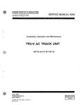
See Figure 4-4 for the set up of this test equipment.
*Or equivalent
FREQ.
METER
:@900 OHM
....
OSCILLATOR
'"
8 OHM
R1
:Wl:
A
AMPLIFIER
I
OSCILLOSCOP:
1
2
-
T
623-:".:;,
..
4-:~
R2
1K
OHM
4.4.3.2
l.
Test Procedure
Oceration
Measure the transto:mer primary and
secondary coil resistances.
l.
2.
To perfo:r::n an operational test on
transformer T2, electrically
is.olate it by disconnecting the
orange wires to PCB turret lug no.
l. The connect the transfo:r::ner to
the test circuit shown in Figure
4-4.
2.
3.
Adjust the frequency to 100 Hz.
3.
4.
Adjust the amplifier output level
so that multimeter Vl reads 9.00V
ac RMS (10 mA input current).
4.
5.
Adjust oscilloscope channel l to 10
volts/cm and channel 2 to 5
volts/cm. Set the time/div. to 1.0
msec. per division.
5.
Veri:icat:icn
Resist:ances should read within a
=ange of 2.~7 t:o 2.70 ohms.
Channell should read 49 to 51
volts P-P.
Channel 2 should read 24.5 to 25.5
volts P-i?.
Channel 2 waveform should lead
channel l waveform by 0.2 to 0.3
msec. as shown in Fiaure 4-5.
LAG
1 MSE-:'..
CHANNEL 1
,,
,
,,
,,
, ,'
CHANNEL 2
,
,,
,,
,
IUNION SWITCH & SIGNAL I@]
SERVICE MANUAL 6237A
A memcer of the ANSALOO Group
saoc Corporata Drive. Pittsburgh. PA 15237
APPENDIX A
PARTS LIST
Dual-Frequency
TRU-11 Code Reset Module
N45"1206-0301
".!,
•
'
•
•
August, 1993
A-o/93-3012
P&C MAC-II 6237A
COPYRIOHT 1993, UNION SWITCH & S:GNAL .NC.
PRINTED IN USA
- ,,.
t
'- · -
,,
•
•
'
:
•
\
•
• •
•
ANSALDO
Trasporti
A.1
COMPLETE ASSEMBLY N451206-0301 (See =igu.::e A-1)
I'!':!M
10
15
20
., -
... :::>
30
35
40
45
50
55
60
I
65
70
75
80
85
90
95
100
105
110
115
120
125
130
135
140
145
150
155
160.
165
170
175
180
185
190
195
210
215
220
225
NCTSS:
1.
DESCR:P'!:'!ON
Cover
Body
Mounting !?late (Body)
?lug
Nameplate
Screw, it2 x· l/4 .. Round Heac.
Screw, #8-32 x 3/8" Pan Heac
Washer, #8 Lock
Nut, itS-32 Hex
Reactor
Reactor
Transformer
Reset Printed Circuit. Board
Relay
Screw, H-40 x 1/4" Pan Heac.
Washer, i4 Lock
Screw, H0-32 x 3/8 !?an Heac
Washer, uo Lock
Washer, no Flat
Nameplate
Pop Rivet
Wire, no PVC Blue
Wire, f20 PVC Red
Wire, #20 PVC Black
Wire, t20 PVC Green
Wire, t20 PVC Brown
Wire, no PVC Yellow
Wire, no PVC Orange
Wire, no PVC Gray
Wire, H4 PVC Gray
Tie Wrap
Terminal
Terminal, Right-Angle
Plate, Mounting (Base)
Terminal Post
Washer, 3/16 Flat
Nut, $1-1-24 AAR
Clamp
Screw, #'5-32 x 1/2 Pa:1 Hea<.:!
Washer, #6 :::.ock, Stain.:.ess .S :.ee.:.
Washer, it6 Flat:
Nut, #6-32 He:<
Refer to sect.iun _...,.' __., :or c:::m;;cner:t:
I US&S
NOTES
!?ART NC.
:
N451207-1202
N4512n-!. 701
· N451207-!.906
I Jona1a
M451496-8503
J525007
J050985
J047681
J048:66
N45l039-5701
N451039-5702
N451039-4104
N451807-7601
J726l53-0157
J507297-0104
J047i65
J507266
J047733
J475077
M451!.08-5202
J490029
A045505-0002
A045505-0006
A045505-0001
A045505-0004
A045505-0003
A045505-0009
A045505-C005
A045505-0007
A0455l9-0005
J703302
J731476
J731399-0073
N451207-1102
Mll5706
I J04,5oo
J480301
M381298
I J507022
J457121-0107
1
J047996
C-0481-48
I
1
I
I
I
I
!
@
@~
~\
55
70
(§@90
.
F:..gure ..'""\--.
Gn.i.-: C.::rr.p:e-:-:
.;-2
)
SC:CTION "A"-"A"
5237.;, p . .;-3
A.2
RESET PCS N4:1907-7601 (See Figure A-2)
ITEM
Cl
C2
Kl
06-09
TLl-6, Rl, R2, R6
Rl
R2
R3
R4
RS
R6
Tl
Dl-!>5
DESCR!PTION
Capacitor, 47 mFd, 20V de
Capacitor, 4'700 mFd, 16V de
Relay, 12V de, SPOT
Diode, lN4005, 600V
Tu.::rec Lug
Resistor (TBD)
Resisi::or, 300 Ohm, 1/2 w
Resistor, 680 Ohm, l/2 w
Resisi::or, 27K Ohm, l/2 w
Thermisi::or, 100 Oh.'1\
Resistor (TBD)
Transfor.ner
Diode
Tie-Cable Clarno
I US&S
!?ART
NO.
II J,06254
I
J709l45-0857
j J726153-0080
I J723s6a
I J71413a
J72125l
J720773
J720759
J731405-0021
J731400-0054
J726l50-0274
J703372-0003
II
SN:
REV:
C2
+
ISS·A
•"' r,..
Q
c
=
.,....
7
9
10 12
1
3
4
(':,
c:
6
!ml
RESET PCS
~N451807·76
@US&SI
MADE IH USA
5237 ..~,
~
.... _