1
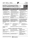
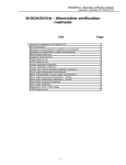
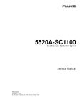
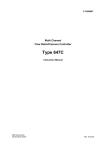
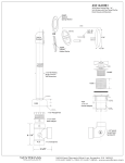
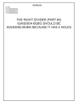
A New Method for the Calibration of the mV Ranges
of an AC Measurement Standard
Speaker/Author
Neil Faulkner
Fluke Corporation
PO Box 9090, Everett, WA 98206
Phone: (425) 446-5538
FAX: (425) 446-5649
E-mail: [email protected]
Abstract
Presented are different methods for the calibration of an AC Measurement Standard from 20 mV
to 2 mV, 10 Hz to 1 MHz. The two methods currently used for this calibration are the
comparison to an AC/DC Transfer Standard and the use of the bootstrap method given in the
manufacturer’s service manual. A new method has been developed using the AC/DC Transfer
Standard with a resistive voltage divider in a way that gives better Test Uncertainty Ratios
(TURs) then the current methods. This paper describes these methods, sources of error and ways
of reducing these errors. Also shown are test results comparing the methods [1].
1. Introduction
The Fluke 5790A AC Measurement Standard [2] is calibrated in the Fluke Labs by comparison
to a Fluke 792A AC/DC Transfer Standard on all ranges from 1 kV down to the 70 mV range but
is not used to verify the 20 mV range and below. The reason for this is low test uncertainty ratios
(TURs) and noise. Instead the bootstrap method as given in the service manual is used. Tests run
during the development of the 5790A showed this method to work with adequate TURs but some
labs and accrediting bodies have been hesitant to accept this method without further verification.
So a new method was developed which gives excellent results that can be used instead. This
method uses a resistive voltage divider in conjunction with the 792A. This paper presents the
challenges encountered in developing the divider method and how they were overcome. Once
developed the divider method was used to evaluate the bootstrap method. This testing is still
ongoing but the results so far indicate that the bootstrap method does work as originally intended
The testing has also revealed ways of improving the method to get better results if so desired.
Lastly test results with the different methods are presented.
2. Direct Measurements with 792A
The 5790A is verified on the 70 mV range and above by connecting the input of a 792A to the
input of the 5790A under test using a type N TEE and driving both with the output of a calibrator
such as the 5700A. The calibrator supplies both the AC and DC Voltage needed for the test. The
most important requirement for the 792A is that its uncertainties be low enough to give a good
TUR at all the test points. At the time this product was developed the uncertainties for the 792A
on its 20 mV range resulted in low TURs so it could not be used to do these ranges. The better
uncertainties available today on the 20 mV range does result in acceptable TURs at 20 mV and
may also at 6 mV and 2 mV depending on where the 792A is calibrated.
2004 NCSL International Workshop and Symposium
Another consideration when using the 792A is noise in the measurement, both low frequency
and high frequency. Since the 792A is an AC/DC device, the calibrator must supply a rather low
level of DC Voltage. Since most calibrators have a 100 mV to 300 mV as their lowest DCV
range, supplying DCV at 20 mV and below has a significant floor error since the voltage is at
tenth scale to one hundredth scale. Also any DC offset voltage drift during the test is not entirely
cancelled by the polarity reversal that is done. These offsets comes from the Thermal EMF
voltages of the connections and offset voltages in the instruments. There is also a problem with
high frequency noise. Most calibrators output some high frequency noise on the DC output and
when operating near the bottom of the range this noise can add significantly to the RMS value of
the DC Voltage. The 792A operates to 1 MHz and so it will respond to noise up to several MHz.
This places an error in the DC Measurement. There are ways of overcoming the noise problems
so a direct measurement with the 792A is possible down to 2 mV but the details of this are not
part of this paper.
3. Measurement with 792A and Resistive Voltage Divider
Using a 792A with a resistive voltage divider can provide a way to measure a 5790A down to the
2.2 mV range with good TURs even when the 792A doesn’t have a calibration with low enough
uncertainties to do a direct measurement. Figure 1 shows a simplified diagram of how such a
divider is used. It is connected between the output of the calibrator and the input of the 5790A
under test (UUT). The 792A is connected to the input of the divider. An appropriate division
ratio is used to allow the calibrator to operate at a high enough voltage that it performs well and
also where the uncertainties of the 792A are low. At the same time it provides the mV signal
with a good signal to noise ratio. Before the divider is used, its division ratio at each test
frequency is determined using the 792A. The voltage applied to the UUT is found by multiplying
the input voltage as measured by the 792A times the division ratio for that frequency.
SOURCE
DIVIDER
HI
5790A
I
792A
LO
HI
LO
Figure 1. Simplified diagram of divider connections and current flow.
2004 NCSL International Workshop and Symposium
The divider is calibrated with the 792A before it is used. The 792A is first used to characterize
the UUT at the voltage level the divider will be putting out when calibrated. Then the divider is
connected as shown in Figure 1 and the 792A measures the input voltage to the divider while the
characterized UUT measures the output voltage. From these two voltages the division ratio is
found. This process is repeated for all the test frequencies. It was desired to have one division
ratio work over the 20 mV to 2 mV range and still be able to calibrate it at a high enough voltage
to get low uncertainties. A division ratio of 100:1 was picked as the best choice. This allows the
input voltage to be between 2 V and 0.2 V which works well for both the calibrator and the
792A. The voltage at which the divider is calibrated is a compromise between two factors. The
higher the voltage the better to minimize the errors when characterizing the UUT but if it is too
high then there is a problem with the power dissipation within the divider. It was found that an
input of 10 V with an output of 100 mV or an input of 6 V with an output of 60 mV was the best
choice. Of these two choices the 6 V in is the best if the uncertainties of the 792A are low
enough at 60 mV; if not then use 10 V in and 100 mV out.
4. Design problems to overcome with the divider method
There were several problems to be overcome designing a divider that would perform to the
desired uncertainty[3]. Figure 1 shows the flow of current between the devices. Most of the
current that flows through the divider and 792A input impedance returns through the Source LO
connection back to the calibrator but some of it can also flow through the UUT LO path due to
the capacitance between the LO and ground. At low frequencies this current is very small and the
common mode rejection of the UUT is very high so it contributes no significant error. As the
frequency goes up the current increases through the capacitance and the common mode rejection
of the UUT decreases so that above 100 kHz or so a significant error can occur. For a typical
divider setup this error will be very significant at 1MHz so something must be done to reduce
this current. Figure 2, on the next page, shows what was done to accomplish this.
First the cable from the divider to the source is kept as short as possible and uses large gauge
wire, one foot of #18 wire in our case. Secondly a short heavy braid strap is connected between
the source Ground terminal and the 5790A Guard terminal and the 5790A is set to EXT GRD.
Figure 2 shows the connections for a 5790A that has the Guard Modification. For a 5790A that
doesn’t have the modification this strap should be connected to the Ground terminal on the
5790A and the 5790A set to INT GRD. The 5700A was also set to EXT GRD and its Guard
connection brought to the divider and connected to the divider output low after the common
mode choke. Tests showed that this was the best connection scheme and almost any deviation
from this gave poor results at 1 MHz.
Next a common mode choke was placed on the output of the divider. This choke places
inductance in series with the common mode current while not affecting the normal mode current
flowing through the HI and LO leads of the UUT. Care should be taken when building the choke
to minimize the normal mode inductance introduced by the windings. A good way to do this is to
use coax. Our unit was built by winding a few turns of miniature coax through a very high mu
ferrite core. The inductance in series with the common mode current needs to be about 150 µH to
250 µH at 1 MHz. If the core has a high Q then there will be a problem around 100 kHz where
the inductance of the choke resonates with the capacitance in the 5790A. This forms a
2004 NCSL International Workshop and Symposium
5700A
Short
Cable
5790A
DIVIDER
OUT HI
No
Cable
SNS HI
CM
CHOKE
Zin
HI
SNS LO
OUT LO
EXT
GRD
50
LO
GUARD
GND
GUARD
792A
No
Cable
HI
LO
EXT
GRD
Strap
HI
Rin
LO
DMM
Figure 2. Complete diagram of divider and connections
series resonant circuit where the series impedance goes to near zero. This allows a lot of current
to flow through the LO path to the 5790A at the resonant frequency. To greatly reduce this effect
a resistor can be placed across the choke on the LO side which reduces the Q of the series circuit.
The value depends on the Q, but for a high Q core, 75 Ohms is a good choice.
Another way of dealing with the common mode current is to break the current path between the
UUT and ground. Normally the UUT is grounded through the power cord and also can be
grounded by means of mounting hardware if installed in a rack. There is also a path to ground
through the IEEE-488 cable. If the UUT can be isolated from ground well enough then the
divider would not need a common mode choke. To break the path through the power cord the
UUT could be powered off a battery and inverter. Test would need to be run to ensure that any
switching transients from the inverter did not affect the UUT measurements. Another way is
through the use of a very low capacitance isolation transformer. This transformer would need to
have very low capacitance from its secondary to ground. Not all types of isolation transformers
on the market have particularly low capacitance from secondary to ground. To isolate the IEEE488 connection an IEEE-488 isolator could be used, but again it is the low capacitance to ground
that is important, not just the isolation across the unit. If possible try and get the total capacitance
to ground to less than 100 pF.
In some setups it was also found that a common mode choke between the 792A DC output and
the DMM input gave better results at 2 mV and 1 MHz. This choke can be made by winding a
2004 NCSL International Workshop and Symposium
few turns of the cable on a ferrite core. To determine if it is needed, take measurements with and
without it and if there is a significant difference then use it.
Another consideration is the value of the resistors in the divider and what range of values is best.
The higher the resistance, the less power is dissipated in the upper arm of the divider. The lower
the resistance the less the effect the UUT input loading has on the divider output. The divider
doesn’t need to have a flat frequency response since its response is measured, so the upper arm
can consist of a large number of resistors in parallel to handle the power. Our divider, built to be
calibrated at 10 V, used forty 1/8 W metal film resistors in parallel. An output resistance of
50 Ohms, which makes the upper arm about 5 kOhms, is the upper limit of resistance to use.
With 50 Ohms the error in the measurement at 1 MHz due to the change in loading from the
range on which it was calibrated to the range on which it is used on can be significant. Data will
be presented later in this paper on this. A lower resistance like 20 Ohms or less would reduce this
error but increase the power dissipated in the upper arm.
Another consideration is to keep the lead length of the connections between the 792A and the
input of the divider as short as possible. The 792A has a low input impedance on its 2 V range
and above so it draws more current than the divider does. This input Z also changes significantly
with range, which changes the current it draws and the voltage drop across the leads. The divider
was built so the 792A connects directly to the divider housing without any cable and uses a
layout inside the housing to keep the leads very short. If the divider is calibrated at 10 V in, the
input Z of the 792A is 4 kOhms. When the divider is used to calibrate a UUT the input voltage
is first set to 2 V to get 20 mV out. If the 792A is set to the 2.2 V range its input Z is 420 Ohms.
This large a shift in resistance and thus current drawn by the 792A caused a noticeable shift in
the results at 1 MHz. For better results the 2 V should be measured on the 7 V range where the
input resistance is 1200 Ohms. The best results can be obtained by calibrating the divider with
6 V in and 60 mV out. This places the 792A on the 7 V range when calibrating the divider and
then the 792A can stay on this same range to measure the 2 V input. Using 6 V to calibrate the
divider also reduces the power the divider must handle. The next range down on the 5790A is the
7 mV range which requires an input of 600 mV. Here the 700 mV range of the 792A is used
which has a high input Z so the current drawn goes way down and is no longer a problem.
Another consideration is the DC connection. Since the 792A is an AC/DC device an accurately
known DC voltage must be presented to the input of the divider. The 792A and divider draw
enough current that a four wire connection may be needed right to the input of the divider so
remote sensing can be used.
The loading of the divider output resistance by the UUT input Z was mentioned earlier. The
affect this loading has on the division ratio at each frequency is accounted for in the calibration
of the divider but only for the UUT range on which it was calibrated. There is some shift in the
loading from range to range which would change the ratio. The amount of change goes up with
frequency so the biggest change is at 1 MHz. The amount of change also differs from UUT to
UUT. To account for this the loading of each frequency above 100 kHz on each range can be
measured. From this, the shift in the divider ratio can be determined and corrections applied. In a
previous paper,[4] a description was given as to how to measure the loading of an AC Voltmeter.
The connection diagram in that paper was for a 792A.
2004 NCSL International Workshop and Symposium
5700A
OUT HI
5790A
200:1
DIVIDER
Coax
Cable
No
Cable
199
OUT LO
INT
GRD
1
HI
Zin
R
LO
GUARD
GND
GUARD
EXT
GRD
Strap
Figure 3. Diagram for the measurement of 5790A loading
Figure 3 shows the setup that should be used for a 579A that has the guard modification. For a
unit without the guard modification, connect the braid strap to the Ground terminal instead of the
Guard terminal and use Internal Guard. Here again following this connection scheme is very
important to the success of the measurements at high frequencies. As mentioned in the
referenced paper this technique depends on the use of a low output Z source. Since most sources
are 50 Ohms output Z in the mV ranges a divider can be built with a low output resistance to
supply the voltage. Figure 3 shows a 200:1 divider with a 1 Ohm output Z that can be built using
inexpensive resistors. A large number of resistors can be paralleled to handle the power in the
upper arm. The resistor with the switch across it must be placed right at the UUT input and its
value should be same as the output resistance of the divider in Figure 2. The 200:1 divider shown
in Figure 3 can be placed at the source output terminals and connected with a coaxial cable to the
resistor with the switch. A common mode choke will probably not be needed as the measurement
process only depends on the change in the UUT reading when the switch is closed. An
alternative to correcting for the loading change would be to use an average change for the UUT
and put an uncertainty component in the uncertainty analysis for the variation of this change
from unit to unit. Data on this will be presently later in this paper that shows that this uncertainty
is only really significant at 1 MHz.
5. The bootstrap method
The bootstrap method as given in the 5790A service manual was developed as a means of
calibrating the 20 mV range and below because, at the time of the 5790A product development,
the uncertainties available on the 792A were not low enough to allow for acceptable TURs in
this range. At that time tests were run to determine the magnitude of the errors in the bootstrap
method and the specifications were adjusted to insure that this method gave acceptable TURs.
With the development of the divider method as described above it became possible to look again
2004 NCSL International Workshop and Symposium
at the sources of error in the bootstrap method and determine their magnitude using a method
with good TURs. This process is still under way and the full results will be published later.
Sufficient work has been done though to identify the two major sources of error and ways of
determining their magnitudes so corrections can be made to the results. This has resulted in an
enhanced bootstrap method that has better TURs.
The major error contributor at low frequencies was found to be the linearity error from full scale
to the bottom of the range, which is one-third scale. In other words the error in proportional parts
at full scale was not the same as at one-third scale. The bootstrap method depends on this
linearity error to be within certain limits for the method to work with acceptable uncertainties.
The bootstrap method starts by measuring the error of the 70 mV range at 60 mV using the
792A. Then with the UUT still on the 70 mV Range, 20 mV is sourced at all the test frequencies
and readings taken from the UUT. Next the range is changed to the 22 mV range and readings
taken again at 20 mV at all the test frequencies. The shift in the readings in proportional parts at
20 mV between the ranges is the error of the 22 mV range relative to the error at the bottom of
the 70 mV Range. The error at the top of the 70 mV range is known in proportional parts so if
the range is linear the two errors can be added together to get the 20 mV error. To what degree
the 70 mV range is not linear, causes an error in the measurement of the 22 mV range at full
scale. Measurements were made using the divider to determine this linearity error and the results
showed that the error was relatively constant over the low frequency range of 10 Hz to 100 kHz.
It was also found that a good determination of the linearity error could be made using
measurements made with DC voltage. The 5790A is not specified for DC operation at 20 mV
and below but it is DC coupled on these ranges so DC measurements can be made. By adding an
extra step to the bootstrap method for each range, most of the linearity error can be determined
and a correction made. This extra step involves applying +DC and –DC at 60 mV and 20 mV on
the 70 mV range. The average of the +DC and the –DC is taken for each level. The average is
taken to cancel significant DC offset voltages that are present. The linearity error in proportional
parts is determined by taking the error from nominal in proportional parts at 20 mV and subtract
the error from nominal in proportional parts at 60 mV. This correction is then applied to all
frequencies. The same process is then done on the 22 mV range when doing the 7 mV Range and
on the 7 mV Range when doing the 2.2 mV Range. It should be noted that when applying the DC
voltage, noise and short term drift of the offset voltages can make it difficult to get a good
measurement so it is generally required to average multiple readings in each polarity and reverse
the polarity more than once. Measurements on a number of units showed that the maximum error
that the linearity error contributed to the calibration of any of the ranges was about 40% of the
specification for that range with the average around 15%. Using the DC measurements reduced
this error to less than 10% in most cases. Again this is some what preliminary results.
The major error contributor of the bootstrap method at high frequency is the change in the
loading of the UUT from range to range. The source of voltage for this test is a calibrator which
has a 50 Ohm output impedance. This 50 Ohms is loaded by the input Z of the UUT. Its input Z
decreases as the frequency goes up and also changes some between ranges for the same
frequency. So in the example given above for calibrating the 22 mV range from the 70 mV
range, the 20 mV as measured on the 70 mV range can change when the UUT is switched to the
22 mV range if the loading of the UUT changes between the two ranges. The amount of this
change is different from instrument to instrument but test on a number of units showed that at
2004 NCSL International Workshop and Symposium
most it contributed an error that was about 15% of the 5790A specification with the average
being about 6%. This is small enough that it isn’t worth measuring the loading of each unit under
test but instead an uncertainty component can be put in the uncertainty analysis for this. In the
next section results of testing of the loading of a sample of 5790As will be given to give an idea
of the typical shift and the variance of this shift.
6. Test results – divider design
One of the most important parts of the design of the divider is the use of a common mode choke
that will effectively reduce the level of common mode current going through the UUT LO lead.
Figure 4 shows the results of testing done on a UUT at 2 mV using a divider with a CM Choke
with adequate inductance and without any choke. For this particular setup three turns on the
ferrite core was sufficient to get good results so that at 1 MHz the measured error was close to
zero. On the other hand, making the same measurement without a choke resulted in a measured
error that exceeded the 5790A specification at 1 MHz. In both cases the divider was calibrated at
10 V before being used to make the measurements. There are two ways to determine how much
inductance is needed for a particular setup. One way is to add turns to the core until adding more
turns doesn’t change the measurement outcome at 2 mV and 1 MHz. The other way is to start
without a choke on the output of the divider but have isolation on the UUT power and IEEE-488
Port so no common mode current can flow through the unit. Take measurements, then remove
the isolation and add the choke and repeat the measurements. If there is enough inductance then
there will be little difference in the results.
8000
6000
+ Spec
4000
- Spec
3T Choke
Error (µV/V)
2000
No Choke
0
100 k
200 k
300 k
400 k
500 k
600 k
700 k
800 k
900 k
1000 k
-2000
-4000
-6000
-8000
Frequency (Hz)
Figure 4. Effect at 2 mV of using a common mode choke on the output of the divider
2004 NCSL International Workshop and Symposium
An important consideration in designing the CM choke is dealing with the series resonant effect
it has with the capacitance in the UUT. As mentioned earlie,r a low Q core can be used and/or a
resistor placed across the LO side winding. Figure 5 shows the effect such a resistor has on a
high Q core. Shown is the division ratio of the divider as a function of frequency from 10 kHz to
1 MHz. The line labeled “No R” is the choke without any means of reducing the series resonant
effect. As can be seen there is a substantial variation in the ratio around 100 kHz that would
cause a problem when using the divider at 100 kHz. The line marked “75 Ohms” shows the
effect of putting a resistor across the LO side winding. Only a small dip remains which does not
cause an error when using the divider because it is accounted for when the divider is calibrated.
The line marked “ISO” for isolation shows the complete lack of any resonant effect when the
UUT is isolated from ground.
2000
Divider Ratio, Deviation from Nominal (µV/V)
1500
1000
500
0
10 k
100 k
1,000 k
-500
No R
-1000
75 Ohms
ISO
-1500
-2000
Frequency (Hz)
Figure 5. Affect of series resonance on the divider ratio.
Another consideration in the design of the divider is the effect that the change in loading of the
UUT under test has on the divider ratio as the range is changed during the tests. As described
earlier, the lower the output resistance of the divide,r the less the effect the UUT loading has on
the division ratio. Tables 1 shows the results of loading measurements on sixteen different
UUTs. These units had date codes from early production to current production. The table shows
the average error that the change in loading would have when using a divider with a 50 Ohm
output resistance. Also shown is one standard deviation of the distribution of the measurements.
Table 1 is for a divider that is calibrated at 10 V in and 100 mV out but it can also be used for a
divider that is calibrated at 6 V in and 60 mV out as the differences in loading errors and
2004 NCSL International Workshop and Symposium
standard deviations is insignificant. It can be seen from the table that the loading error is only
significant at 1 MHz when compared to the 5790A Specifications. So a good option is to not
measure the loading change of each UUT but instead use the values in the table as a correction at
1 MHz and use the standard deviation in the uncertainty analysis. In the Table 1, a negative sign
indicates that there is more loading on the range given in the table than there is at 100 mV. So
the value in table can be applied as a correction to the divider ratio for that range. It should be
noted that this table is for a 50 Ohm divider only and can not be scaled for use with dividers of
other output resistances. This is because there is a non linear relationship between the divider
output resistance and the error due to the change in loading. In other words, a 25 Ohm divider
would have less than half the loading error shown and a 100 Ohm divider would have more than
twice the error.
Table 1. Error from change in loading as it affects a 50 Ohm divider.
5790A
Range
22 mV
22 mV
22 mV
7 mV
7 mV
7 mV
2.2 mV
2.2 mV
2.2 mV
Test
Freq
Hz
300 k
500 k
1M
300 k
500 k
1M
300 k
500 k
1M
Average
Loading Error
µV/V
25
60
85
20
20
65
15
-70
-285
Standard
Deviation
µV/V
10
20
110
20
30
190
45
75
525
5790A
90 d Spec
µV/V
1010
1160
1700
1867
2300
3000
4300
5400
6200
It was mentioned earlier that the change in loading of the UUT from range to range also affects
the results of the measurements made with the bootstrap method. Table 2 shows the errors and
standard deviations of the sixteen units tested as they apply to the bootstrap method. These too
can be used as corrections and uncertainties but only apply for a source with a 50 Ohm output Z.
Table 2. Error from change in loading as it affects the bootstrap method
5790A
Range
22 mV
22 mV
22 mV
7 mV
7 mV
7 mV
2.2 mV
2.2 mV
2.2 mV
Test
Freq
Hz
300 k
500 k
1M
300 k
500 k
1M
300 k
500 k
1M
Average
Loading Error
µV/V
25
60
110
-5
-35
-25
0
-90
-315
2004 NCSL International Workshop and Symposium
Standard
Deviation
µV/V
10
20
100
15
20
90
40
55
350
5790A
90 d Spec
µV/V
1010
1160
1700
1867
2300
3000
4300
5400
6200
7. Test results – measurements on UUTs
Several UUTs were measured using all the methods to see how well they agree. All test points
were measured using the divider method, the bootstrap method and the enhanced bootstrap
method. For the enhanced bootstrap method measurements were taken with DC voltage to
correct for the range linearity error. Also the actual change in loading of each unit was measured
and applied as a correction to the divider method and enhanced bootstrap method. Measurements
with the 792A were made at 20 mV and 6 mV at all frequencies but at 2 mV the uncertainty on
our 792A was only low enough for four frequencies to be measured.
Figure 6 shows the measured errors at 20 mV for a UUT that had the largest linearity error found
amount several units tested. As shown in the figure there is good agreement between the
measurements done with the 792A and using the divider method. The difference between these
measurements and the bootstrap method is about 35% to 40% of the 5790A Specification. This
difference was reduced to about 15% with the enhanced bootstrap method. For most units tested
it was reduced to less than 10%. Figure 7 shows the measurements on this same 5790A from
100 kHz to 1 MHz. The maximum difference between the four methods, including the bootstrap
method which isn’t shown, was 10% or less with most points at 6% or less of the 5790A
Specification.
200
+ Spec
180
792A
Divider
160
Bootstrap
Error (µV/V)
140
Enhanced
120
100
80
60
40
20
0
0.1 k
1.0 k
10.0 k
100.0 k
Frequency (Hz)
Figure 6. Test results at 20 mV, 100 Hz to 100 kHz, for the four methods.
2004 NCSL International Workshop and Symposium
2000
1500
+ Spec
- Spec
1000
792A
Divider
Error (µV/V)
500
0
100 k
Enhanced
200 k
300 k
400 k
500 k
600 k
700 k
800 k
900 k
1000 k
-500
-1000
-1500
-2000
Frequency (Hz)
Figure 7. Test results at 20 mV, 100 kHz to 1 MHz, using 792A, divider and enhanced methods
800
+ Spec
600
- Spec
792A
400
Divider
Enhanced
Error (µV/V)
200
0
100
1000
10000
100000
-200
-400
-600
-800
Frequency (Hz)
Figure 8. Test results at 6 mV, 100 Hz to 100 kHz, using 792A, divider and enhanced methods
2004 NCSL International Workshop and Symposium
Figure 8 shows the measurement results on a different UUT at 6 mV, 100 Hz to 100 kHz, using
the 792A, divider method and enhanced bootstrap method. The bootstrap method was not shown
because the linearity error on this unit was small. The maximum difference between the divider
and enhanced methods was 9% of the 5790A Specifications. The maximum difference between
the 792A measurements and the other two methods was 19%. Figure 9 shows the measurements
results for 100 kHz to 1 MHz. The largest difference between the three methods was about 10%
of the 5790A Specification. Maximum difference for the bootstrap method, which isn’t shown,
was 15%.
4000
3000
+ Spec
- Spec
2000
792A
Error (µV/V)
1000
Divider
Enhanced
0
100 k
200 k
300 k
400 k
500 k
600 k
700 k
800 k
900 k
1000 k
-1000
-2000
-3000
-4000
Frequency (Hz)
Figure 9. Test results at 6 mV, 100 kHz to 1 MHz, using 792A, divider and enhanced method.
Figure 10 shows the measurement results at 2 mV from 100 Hz to 100 kHz on another UUT.
Here again the advantage of using the enhanced bootstrap method over the bootstrap method can
be seen. There is good agreement between the two measurements taken by the 792A, at 1 kHz
and 50 kHz, and the enhanced bootstrap method while the difference for the bootstrap method is
21% and 16% of the 5790A specification respectively. The maximum difference between the
divider method and the enhanced bootstrap method is 12% of the 5790A specification. Figure 11
shows the measurement results at 2 mV from 100 kHz to 1 MHz. The maximum difference
between the divider method and the 792A, which is at 1 MHz, is 11% of the 5790A
specifications while the maximum for the enhanced method is 6%. For the bootstrap method,
which is not shown, it was 20%.
2004 NCSL International Workshop and Symposium
1200
+ Spec
1000
792A
Divider
800
Bootstrap
Error (µV/V)
600
Enhanced
400
200
0
0.1 k
1.0 k
10.0 k
100.0 k
-200
-400
Frequency (Hz)
Figure 10. Test results at 2 mV, 100 Hz to 100 kHz, using the four methods.
8000
6000
+ Spec
- Spec
Error (µV/V)
4000
792A
Divider
2000
0
100 k
Enhanced
200 k
300 k
400 k
500 k
600 k
700 k
800 k
900 k
1000 k
-2000
-4000
-6000
-8000
Frequency (Hz)
Figure 11. Test results at 2 mV, 100 kHz to 1 MHz, using 792A, divider and enhanced.
2004 NCSL International Workshop and Symposium
8. Conclusion
The uncertainty analysis for the divider method shows that it has a TUR of about 4:1 at 20 mV
and 5:1 or better at 6 mV and 2 mV. The comparison data to the 792A given in this paper
substantiates this analysis. This comparison data also shows that the bootstrap and particularly
the enhanced bootstrap probably have good TURs also but further work is in progress to
determine their level of performance. The results of this work will be published when complete.
References
1. Some of the material in this paper was presented in the two page abstract: N. Faulkner,
“Comparing Different Methods for the Calibration on the mV Ranges of an AC Measurement
Standard”, Conference on Precision Electromagnetic Measurements, Conference Digest,
London, UK, June 2004.
2. D. Deaver, “Calibration and Traceability of a Fully Automatic AC Measurement Standard”,
NCSL Workshop & Symposium, Albuquerque, NM, USA, Aug 1991. Available on the Fluke
web site: www.fluke.com.
3. “Calibration: Philosophy in Practice”, 2nd Edition, pp. 32-4 to 32-6, Published by Fluke
Corporation, Everett, WA. USA, 1994.
4. N. Faulkner, “How the Loading of an AC/DC Transfer Standard can Effect your Measurement
of AC Voltage and Current” 1999 NCSL Workshop and Symposium, July 1999. Available on
the Fluke web site: www.fluke.com.
2004 NCSL International Workshop and Symposium
100:1 Divider Construction
Common Mode choke
at divider output.
(miniature coax on high
Q core)
Divider
Output
(5790A)
50 Output Resistor
(Low TC metal film)
75 resistor to lower
Q of coil
Divider
Input (792A)
Cable to Source
(5700A)
5000 Input Resistor
(40 50k low TC metal film
Series/Parallel)
2004 NCSL International Workshop and Symposium