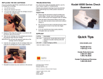
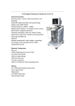
1
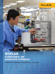
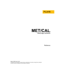
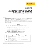
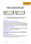
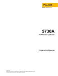
52120A
Transconductance
Amplifier
Expand the workload capability of your
power and electrical calibrators
52120A Transconductance Amplifier
Fluke Calibration 2
2 Fluke Calibration
52120A Transconductance Amplifier
52120A
Transconductance
Amplifier
The Fluke Calibration 52120A Transconductance Amplifier supplies dc current
up to 100 amps and ac current up to 120 amps at accuracies to 140 ppm. Using
accessory coils, it can generate 3,000 or 6,000 amps. Three 52120As connected in parallel can output up to 360 amps. Inductive drive capability of 1 mH
and compliance voltage of 4.5 volts support a wide range of applications.
Expand the workload capability of your
power and electrical calibrators
The 52120A is designed for users whose ability
to address their calibration workload may be
limited by the output current, accuracy and
drive capability of their present test equipment,
including:
• Calibration professionals in a calibration/standards lab or an electrical utility
• Manufacturers of power/energy instrumentation
and meters, power quality analyzers or power
converters
• Users of electrical test and measurement
equipment
The 52120A enables you to test and calibrate
a broad workload at full current range:
• Primary and secondary power standards
• Power and energy meters
• Power quality analyzers
• Digital multimeters, analog and clamp meters
• High current clamp meters, e.g.: Fluke-345
• Rogowski coils e.g., Fluke i6000 Flex
• Current shunts, probes and transformers
• Relay/breaker test sets
The 52120A operates as a transconductance
amplifier with:
• 5500A/5520A/5522A Multi-Product Calibrator
• 5700A/5720A Multifunction Calibrator
• 5080A Multi-Product Calibrator
• 9100 Universal Calibration System
• Any calibrator, signal generator or power supply
capable of sourcing 2 V or 200 mA, dc or ac
You may also operate your 52120A in closed-loop
mode, seamlessly communicating with your Fluke
Calibration 6105A or 6100B Electrical Power
Standard to deliver enhanced 52120A accuracy.
52120A performance at a glance
• Industry-leading amplifier accuracy:
- 140 ppm ac (used with
61XXA Electrical Power Standard)
- 350 ppm ac (used with dc/lf calibrator)
- 150 ppm dc (used with dc/lf calibrator)
• Frequency: to 10 kHz
• Burden voltage (compliance): 4.5 V @ 120 A
• Inductive drive capability: 1 mH load
• Parallel operation: 2 or 3, up to 360 A in a
single phase
• Accessory coils: 25-turn coil supports 3000 A,
50-turn coil supports 6000 A
• Control communication with 6105A /6100B
Electrical Power Standards
• GPIB remote operation
• Output ranges: 2 A, 20 A, 120 A
• Input ranges: 2 V or 200 mA F.S. for 2 A and 20 A
ranges, 1.2 V or 120 mA F.S. for 120 A range
52120A Transconductance Amplifier
Fluke Calibration 3
Address your high-current
workload with a 120A
Transconductance Amplifier
•
•
Output dc to 10 kHz
•
Drive accessory coils
for 3000 A or 6000 A
Parallel operation for
240 A or 360 A
1
Features
1
6 mm terminals for outputs to 120 A
2
4 mm terminals for outputs up to 20 A
3
12 V power for Current Coil fans
4
Compliance voltage bar graph
5
Three output ranges; 2 A, 20 A and 120 A
6
LCOMP mode for highly inductive loads
7
Status indicators for operation with 6105A
8
Drive the amp with 200 mA or 2 V
4 Fluke Calibration
52120A Transconductance Amplifier
2
3
4
7
6
5
8
Current Coils support 3000 or 6000 Amps
52120A/COIL3KA
Coil, 25-turn,
3000 Amp
52120A/COIL6KA
Coil, 50-turn,
6000 Amp
52120A Transconductance Amplifier
Fluke Calibration 6
Specifications
General specifications
Input line voltage range
Transient overvoltage
Frequency
Maximum consumption
Dimensions with feet (H x W x L)
Dimensions without feet (H x W x L)
Weight
Design standards and compliance
Operating temperature
Calibration temperature range
Storage temperature
Transit temperature
Warm up time
Safe operating max. relative humidity (non-condensing)
Storage max relative humidity (non-condensing)
Operating altitude
Non-operating altitude
Shock
Vibration
Enclosure
100 V to 240 V with up to ±10 % fluctuations
Impulse withstand (overvoltage); Category II of IEC 60364-4-443
47 Hz to 63 Hz
< 1500 VA
192 mm x 432 mm x 645 mm (7.6 inches x 17 inches x 25.5 inches)
178 mm x 432 mm x 645 mm (7 inches x 17 inches x 25.5 inches)
25 kg (54 lb.)
Designed to EN 61010-1: 2010, CAN/CSA 22.2 No 61010.1-04,
ANSI/UL 61010-1:2004, EN 61326-1:2006 CE marked, CSA listed
5 °C to 35 °C
16 °C to 30 °C
0 °C to 50 °C
-20 °C to 60 °C <100 hours
1 hour
<80 % 5 °C to 31 °C ramping linearly down to 50 % at 35 °C
<95 % 0 °C to 50 °C
0 m to 2,500 m
0 m to 12,000 m
MIL-PRF-28800F class 3
MIL-PRF-28800F class 3
MIL-PRF-28800F class 3
Performance specifications
Electrical performance limits
Operating limits
Output current
Output ranges
Input current range
Input voltage range
120 A range Operating current/
frequency limits[1]
Maximum output compliance voltage [2]
0 A to 120 A
Three ranges: 2 A, 20 A and 120 A
Maximum input
200 mA rms
Output range
2 A rms
Gain
10
Maximum input
2 Vrms
Output range
2 A rms
Transconductance
1 Siemen
DC ±100A
>DC to < 10 Hz max current 70 Arms, 100 Apk
10 Hz to 10 kHz, max current 120 Arms, 170 Apk
4.5 Vrms (6.4 Vpeak) for DC
200 mA rms
20 A rms
100
2 Vrms
20 A rms
10 Siemens
120 mA rms
120 A rms
1000
1.2 Vrms
120 A rms
100 Siemens
The 2A and 20A ranges operate at full output current from DC to 10 kHz.
Available 120 A compliance voltage decreases from 4.5 V at 1 kHz to around 3 V at 10 kHz.
[1]
2]
Output isolation
Frequency
DC to 850 Hz
850 Hz to 3 kHz
3kHz to 10 kHz
Maximum voltage signal applied to any output current terminal with respect to earth
600 Vrms, 850 Vpeak
100 Vrms, 142 Vpeak
33 Vrms, 47 Vpeak
Operated within 6105A or 6100B control loop, Sine or Harmonic input, all 52120A current ranges
1 year accuracy, tcal[1] ± 5⁰ C ± (% of output + % of FR[2])
Frequency
6105A
6100B
% output
+% FR
% output
+% FR
DC
0.015 %
0.010 %
0.022 %
0.025 %
16 Hz to 850 Hz
0.011 %
0.003 %
0.018 %
0.003 %
850 Hz to 6 kHz
0.052 %
0.005 %
0.052 %
0.005 %
6 kHz to 9 kHz
Use stand-alone performance specification below
tcal is the temperature at which calibration adjustment took place, [2] FR = Full range.
Note: Maximum inductance for stability LCOMP OFF is 100 µH. Maximum inductance for stability LCOMP ON is 400 µH for 2 A and 20 A ranges,
100 µH on the 120 A range.
[1]
6 Fluke Calibration
52120A Transconductance Amplifier
Operated within 6105A or 6100B control loop, Sine or Harmonic input, all 52120A current ranges (cont’d)
10 Hz to 69 Hz
0.006°
Phase angle accuracy
180 Hz tp 450 Hz 450 Hz to 850 Hz
850 Hz to 3 kHz
0.025°
0.045°
0.325°
Maximum load dependent phase angle shift
<0.001° @ 60 Hz; increasing linearly to: 0.006° @ 6 kHz
69 Hz to 180 Hz
0.012°
3 kHz to 6 kHz
0.645°
Notes: 1. The amplitude accuracy and phase angle specifications above apply for the paralleled output of up three 52120A connected as Slaves
to a single 610X Electrical Power Standard. 2. See 610X specifications for Interharmonic, Fluctuating harmonic, Dip and Flicker specifications.
Stand-alone performance, 2 A range
1 year transconductance and current gain accuracy, tcal[1] ± 5⁰ C ± (% of output + % FR[2])
Frequency
% of output
% FR
LCOMP OFF [3]
LCOMP ON [4]
DC
0.010 %
0.005 %
0.005 %
10 Hz to 65 Hz
0.015 %
0.070 %
0.300 %
65 Hz to 300 Hz
0.030 %
0.070 %
0.500 %
300 Hz to 1 kHz
0.100 %
0.070 %
3.500 %
1 kHz to 3 kHz
0.300 %
0.600 %
Not specified
3 kHz to 6 kHz
1.000 %
1.600 %
Not specified
6 kHz to 10 kHz
2.000 %
4.000 %
Not specified
Stand-alone performance, 20 A range
1 year transconductance and current gain accuracy, tcal[1] ± 5⁰ C ± (% of output + % FR[2])
Frequency
% of output
% FR
LCOMP OFF [3]
LCOMP ON [4]
DC
0.010 %
0.005 %
0.005 %
10 Hz to 65 Hz
0.015 %
0.060 %
0.300 %
65 Hz to 300 Hz
0.030 %
0.060 %
1.200 %
300 Hz to 1 kHz
0.100 %
0.060 %
6.000 %
1 kHz to 3 kHz
0.300 %
0.200 %
Not specified
3 kHz to 6 kHz
1.000 %
0.400 %
Not specified
6 kHz to 10 kHz
3.000 %
0.600 %
Not specified
Stand-alone performance, 120 A range
1 year transconductance and current gain accuracy, tcal[1] ± 5⁰ C ± (% of output + % FR[2])
Frequency
% of output
% FR
LCOMP OFF [3]
LCOMP ON [4]
DC
0.010 %
0.005 %
0.005 %
10 Hz to 65 Hz
0.015 %
0.020 %
0.500 %
65 Hz to 300 Hz
0.030 %
0.030 %
0.700 %
300 Hz to 1 kHz
0.100 %
0.100 %
3.500 %
1 kHz to 3 kHz
0.300 %
0.250 %
Not specified
3 kHz to 6 kHz
1.000 %
0.450 %
Not specified
6 kHz to 10 kHz
4.000 %
0.750 %
Not specified
[1]
[4]
tcal is the temperature at which calibration adjustment took place, [2] FR = Full range, [3] Maximum inductance for stability LCOMP OFF is 100 µH,
Maximum inductance for stability LCOMP ON is 1mH
Up to ten 52120A (one Master, nine Slaves) can be chained together in stand-alone mode. Any additional Slave units will be ignored by the control system.
Notes
1. The specifications above are stated with a coverage factor k=2.58 equivalent to 99 % confidence level.
2. The Stand-alone specifications are for the accuracy of transconductance with a voltage input or current gain with a current input.
The specifications do not include the errors of the instrument providing the voltage or current signal to the Product input. To get the
absolute accuracy of the current output the source and Product specifications should be combined using the “root sum of squares” (RSS)
method which is explained in Chapter 4 of the 52120A User’s Manual.
3. Voltage compliance developed across inductive loads may prevent range maximum current output being achieved at higher
frequencies. The approximate maximum frequency (Fmax) for given load inductance and current is given by:
Fmax =
4.5
(2 x π x I x L)
where I is the current and L the total inductance.
The maximum frequency calculated with this equation is only approximate. Series resistance and parallel capacitance
also affect the maximum achievable frequency.
52120A Transconductance Amplifier
Fluke Calibration 7
Ordering information
Models
52120A
Transconductance Amplifier, 120A
Options and accessories
52120A/COIL3KA Coil, 25 turn, 3000 Amp
52120A/COIL6KA Coil, 50 turn, 6000 Amp
52120A/COIL12V Coil 12 V DC Supply
GCP 52120
CarePlan one year
G3P 52120
CarePlan three years
Fluke Calibration. Precision, performance, confidence.™
Fluke Calibration
PO Box 9090,
Everett, WA 98206 U.S.A.
Fluke Europe B.V.
PO Box 1186, 5602 BD
Eindhoven, The Netherlands
For more information call:
In the U.S.A. (877) 355-3225 or Fax (425) 446-5116
In Europe/M-East/Africa +31 (0) 40 2675 200 or Fax +31 (0) 40 2675 222
In Canada (800)-36-FLUKE or Fax (905) 890-6866
From other countries +1 (425) 446-5500 or Fax +1 (425) 446-5116
Web access: http://www.flukecal.com
©2012 Fluke Corporation. Specifications subject to change without notice.
Printed in U.S.A. 1/2012 4024733B B-EN-N Pub-ID 11871-eng
Modification of this document is not permitted without written permission from Fluke Corporation.
8 Fluke Calibration
52120A Transconductance Amplifier