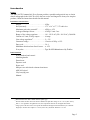
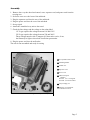
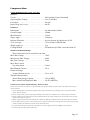
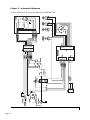
1
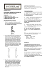
OPERATION AND
MAINTENANCE MANUAL
ARU-01CF
NSN: 6525-01-468-1672
P.O. Box 1548 Woodinville, WA 98072-1548
1-800-426-5913 * 425-487-3157 * Fax: 360-668-8722
email: [email protected] * Internet: www.aseptico.com
P/N 420263
Rev. A
05/00
Table of Contents
Introduction . . . . . . . . . . . . . . . . . . . . . . . . . . . . . . . . . . . . . . . . . . . . . . . . . . . . . . . . . . . . .3
Purpose . . . . . . . . . . . . . . . . . . . . . . . . . . . . . . . . . . . . . . . . . . . . . . . . . . . . . . . . . .3
Performance Characteristics . . . . . . . . . . . . . . . . . . . . . . . . . . . . . . . . . . . . . . . . . .3
Items Furnished . . . . . . . . . . . . . . . . . . . . . . . . . . . . . . . . . . . . . . . . . . . . . . . . . . .3
Safety Precautions . . . . . . . . . . . . . . . . . . . . . . . . . . . . . . . . . . . . . . . . . . . . . . . . . . . . . . . .4
Assembly . . . . . . . . . . . . . . . . . . . . . . . . . . . . . . . . . . . . . . . . . . . . . . . . . . . . . . . . . . . . . . .5
Performance Verification . . . . . . . . . . . . . . . . . . . . . . . . . . . . . . . . . . . . . . . . . . . . . . . . . . .6
Line Voltage Indicator . . . . . . . . . . . . . . . . . . . . . . . . . . . . . . . . . . . . . . . . . . . . . .6
Timer . . . . . . . . . . . . . . . . . . . . . . . . . . . . . . . . . . . . . . . . . . . . . . . . . . . . . . . . . . . .6
Peak Tube Potential . . . . . . . . . . . . . . . . . . . . . . . . . . . . . . . . . . . . . . . . . . . . . . . .8
Tube Current . . . . . . . . . . . . . . . . . . . . . . . . . . . . . . . . . . . . . . . . . . . . . . . . . . . . . .8
Testing Checklist . . . . . . . . . . . . . . . . . . . . . . . . . . . . . . . . . . . . . . . . . . . . . . . . . . .9
Operation Instructions . . . . . . . . . . . . . . . . . . . . . . . . . . . . . . . . . . . . . . . . . . . . . . . . . . .10
Operation . . . . . . . . . . . . . . . . . . . . . . . . . . . . . . . . . . . . . . . . . . . . . . . . . . . . . . .10
Technique Chart . . . . . . . . . . . . . . . . . . . . . . . . . . . . . . . . . . . . . . . . . . . . . . . . . .11
Maintenance . . . . . . . . . . . . . . . . . . . . . . . . . . . . . . . . . . . . . . . . . . . . . . . . . . . . . . . . . . .12
Component Data . . . . . . . . . . . . . . . . . . . . . . . . . . . . . . . . . . . . . . . . . . . . . . . . . . . . .13-16
Table of Illustrations
Figure A - Component Identification . . . . . . . . . . . . . . . . . . . . . . . . . . . . . . . . . . . . . . . . .5
Figure B - Potentiometer Location . . . . . . . . . . . . . . . . . . . . . . . . . . . . . . . . . . . . . . . . . . .6
Figure C - Electrical Pulse Activity During X-Ray Tube Warm-up and Exposure . . . . . .7
Figure D - X-Ray Tube Electrical Performance . . . . . . . . . . . . . . . . . . . . . . . . . . . . . . . . .8
Chart A - Testing Checklist . . . . . . . . . . . . . . . . . . . . . . . . . . . . . . . . . . . . . . . . . . . . . . . . .9
Figure E - Control Panel . . . . . . . . . . . . . . . . . . . . . . . . . . . . . . . . . . . . . . . . . . . . . . . . . .10
Chart B - Technique Chart . . . . . . . . . . . . . . . . . . . . . . . . . . . . . . . . . . . . . . . . . . . . . . . .11
Figure F - Absolute Maximum Rating Charts . . . . . . . . . . . . . . . . . . . . . . . . . . . . . . . . .14
Figure G - Emission and Filament Characteristics . . . . . . . . . . . . . . . . . . . . . . . . . . . . . .14
Figure H - Anode Thermal Characteristics . . . . . . . . . . . . . . . . . . . . . . . . . . . . . . . . . . .14
Figure I - Dimensional Outline . . . . . . . . . . . . . . . . . . . . . . . . . . . . . . . . . . . . . . . . . . . . .15
Figure J - Schematic Diagram . . . . . . . . . . . . . . . . . . . . . . . . . . . . . . . . . . . . . . . . . . . . . .16
Upon Arrival
When the equipment is received, each shipping container should be carefully examined for any
evidence of mishandling during shipment. Note its condition, if abnormal, carefully unpack all
parts and examine for damage. If any damage is noted, immediately report it to the carrier in the
proper manner. All printed matter supplied with the unit should be saved for installation,
operation, and future reference.
Page 2
Introduction
Purpose
The ARU-01CF Command Air X-ray System provides a portable and practical way to obtain
dental radiographs in the field. To receive the best service and longest life from your Aseptico
product, follow the instructions detailed in this manual.
Performance characteristics
Weight: . . . . . . . . . . . . . . . . . . . . . . . . . . . .42 lbs.
Size (external): . . . . . . . . . . . . . . . . . . . . .17.5” x 16” x 17”, 2.75 cubic feet
Maximum peak tube potential1: . . . . . . . .63kVp ± 15%
Leakage technique factors: . . . . . . . . . . . .63 kVp 12 mA 2 sec.
Range of line voltage regulator: . . . . . . . .110 - 130 V AC (220 - 260 V AC), 50/60 Hz.
Current at 12 mA, 63 kVp output: . . . . . .6 Amps
Line voltage regulation2: . . . . . . . . . . . . . .2 ~ 5%
Generator rating3: . . . . . . . . . . . . . . . . . . .12 mA at 63 kVp ± 15%
Duty cycle: . . . . . . . . . . . . . . . . . . . . . . . . .30 : 1
Maximum deviation from fixed factors: . .± 15%
X-ray tube: . . . . . . . . . . . . . . . . . . . . . . . . .Type D-082B Manufactured by Toshiba
Items furnished
X-ray tubehead and control
Mounting handle
Dental cone
Exposure cord
Power cord
Mil-spec case with shock resistant foam insert
ARU-01S tripod
Vinyl carrying case
Manual
1
Measurements taken with a 50mm diameter sphere gap.
2
The stated mA and line current are under conditions of input line voltage of 110 - 130 V (220 - 260 V)
with 2 ~ 5% regulation. If regulation is less, the amps drawn and mA can be higher than stated.
3
Using a precise DC mA meter across points N and NE of the high tension transformer (see schematic
diagram) to measure mA. Input is 117 V AC (230 V AC), 50/60 Hz. Tolerance is ± 15%.
Page 3
Safety Precautions
WARNING - Careless or improper use of x-ray equipment can be extremely hazardous.
WARNING - It is imperative that this equipment be operated and serviced only by trained
personnel familiar with the safety precautions required to prevent excessive exposure
to primary x-ray radiation, the dangers of exposure to x-ray radiation, and the proper
use of the equipment discussed in this manual.
1. During exposure, the operator must stand as far as possible from the patient being x-rayed
and should wear a lead apron or stand behind a lead shield.
2. The operator must not stand in the primary x-ray beam.
3. The operator must wear a monitoring badge while operating this unit. It should be on the
collar, not on an area covered by the lead apron.
4. X-ray exposure should be as short as possible.
All personnel authorized to operate or service this equipment should be fully acquainted with the
established maximum permissible doses, safety recommendations, and procedures derived from
the following sources:
A. National Council on Radiation Protection Report No. 33 (Medical X-ray and Gamma Ray
Protection for Energies up to 10 MEV - Equipment Design and Use); from NCRP
Publications; P.O. Box 30175, Washington, D.C. 20014.
B. National Bureau of Standards Handbook No. 76 (Medical X-ray Protection up to Three
Million Volts); from the Superintendent of Documents, Government Printing Office,
Washington, D.C. 20401.
C. All documents relating to the Performance Standard for Diagnostic X-ray Systems, 21 CFR
Subchapter J, Part 1020; obtainable from FDA Center for Devices and Radiological
Health, Department of HHS, 2098 Gaither Road, Rockville, MD 20850.
D. State and local regulations governing radiation protection and the use of diagnostic x-ray
equipment.
E. Requirements of the user's in-house radiation protection program.
F. Instructions and precautionary notices of this manual.
Although this equipment incorporates protective design features for limiting both the direct
(primary) x-ray beam and the secondary radiation produced by this beam, design factors alone
cannot prevent human carelessness, negligence, or lack of knowledge. This apparatus is sold with
the understanding that the user assumes sole responsibility for radiation safety and that Aseptico,
Inc., its agent and representatives, do not accept any responsibility for:
1. Injury or danger to patient or other personnel from x-ray exposure.
2. Overexposure due to poor operating techniques or procedures.
3. Equipment not properly serviced or maintained in accordance with this manual.
4. Equipment which has been modified or tampered with in any way.
Page 4
Assembly
1. Remove the x-ray tube head and control, cone, exposure cord, and power cord from the
carrying case.
2. Screw the cone on to the front of the tubehead.
3. Plug the exposure cord into the rear of the tubehead.
4. Plug the power cord into the rear of the tubehead
5. Set up tripod
6. Attach the assembled x-ray unit to the stand.
7. Check the line voltage and the voltage on the rating label;
115 V type requires line voltage between 110 and 130 V.
230 V type requires line voltage between 220 and 260 V.
These voltages must be with 15 ampere #12 three-wire service, if not,
the films may be light or show lack of sufficient penetration.
8. Plug the power cord into the wall outlet.
The unit is now assembled and ready for testing.
8
7
1 X-ray tubehead and control
2 Mounting handle
3 Dental cone
6
4 Exposure cord
5 Power cord
6 ARU-01S tripod
1
Includes:
#510311 5/16 - 18 wing-nut
#510322 5/16 fender washer
5
2
3
4
7 Vinyl carrying case
8 Mil-spec case with shock
resistant foam insert
Figure A - Component Identification
Page 5
Performance Verification
The following tests must be conducted without fail before the ARU-01CF Command Air X-Ray
System can be used for radiology. Fill out the checklist for these tests when installation of x-ray
unit is complete.
Line Voltage (LV) Indicator
1-1 LV Indicator Test Method:
Measure voltage of wall outlet, and confirm that the following conditions are fulfilled.
Wall outlet voltage:
130 ~ 125 V (260 ~ 250 V)
Green LED goes on when LV knob turns 1 click clockwise.
125 ~ 120 V (250 ~ 240 V)
Green LED goes on when LV knob turns 2 clicks clockwise.
120 ~ 115 V (240 ~ 230 V)
Green LED goes on when LV knob turns 3 clicks clockwise.
115 ~ 110 V (230 ~ 220 V)
Green LED goes on when LV knob turns 4 clicks clockwise.
110 ~ 105 V (220 ~ 210 V)
Green LED goes on when LV knob turns 5 clicks clockwise.
If the LV indicator needs adjustment:
1. Remove the 4 screws on the cover.
2. Adjust the potentiometer "A" (See Figure B) on the printed circuit board so that the green
LED goes on at the above settings.
3. Replace the cover and the 4 screws.
A
B
+
Figure B - Potentiometer Location
Timer
Since the filament of the x-ray tube is off when the unit is not emitting radiation, it takes
approximately 0.15 seconds (9 electrical pulses) for the x-ray tube filament to warm up be fore an
x-ray is emitted (see Figure C). Because of this warm up time, the electronic timer has a built in
lag of approximately 0.15 seconds, therefore, when checking the timer with a cycle counter, 0.15
seconds must be added to the time set on the timer.
Page 6
Exposure end
Visible Pulses
Warm-up Time
Exposure Time
Total Electrical Pulses
Exposure start
Figure C - Electrical Pulse Activity During X-Ray Tube Warm-up and Exposure
TW = Filament warm-up time
TW = P - Dx
P = Total number of electrical pulses
Dx = Number of readable dots on film as determined by a spin top test
2-1 Timer Test Method:
1. Set timer to 0.08 sec.
2. Set NERO to the following settings.
SID: 18 inches
Wheel range: 50 ~ 85 kV
Sensitivity: Low
Phase Select: 1∅
Measurement Mode: STAT
X-ray values: 63 kV, 0.08 sec.
3. Make exposure and read value of exposure time.
4. Measure value of exposure time at following settings with same procedure:
0.08 sec., 0.10 sec., 0.20 sec., 0.50 sec., 1.00 sec., 2.00 sec.
2-2 Instruments:
NERO Model 6000M X-ray Beam Analyzer, Manufactured by Victoreen, Inc. or equivalent
2-3 Rejection Limit:
± 2 pulse (0.08 sec. ~ 2.0 sec.), ± 10% (0.25 sec. ~ 2.0 sec.)
If the timer needs adjustment:
1. Remove the 4 screws on the cover.
2. Adjust the potentiometer "B" (See Figure B) on the printed circuit board so that the radiation
exposure time equals the time indicated on the timer dial, taking into consideration the
accuracy tolerances.
3. Replace the cover and the 4 screws.
Page 7
Peak Tube Potential
The ARU-01CF has a filament warm-up time of 0.15 sec. (9 electrical pulses) built into its
settings. The kV is as shown on Figure D. For that reason, measure kV with 0.15 sec. delay time.
3-1 Peak Tube Potential Test Method:
1. Set timer to 0.2 sec.
2. Set NERO to the following settings:
SID: 18 inches
kVp
Wheel range: 50 ~ 85 kV
Sensitivity: High
80
Phase Select: 1∅
Measurement Mode: SGL
Time Delay: 0.1 sec.
Peak Tube Potential
63
mA
X-ray values: 63 kV, 0.2 sec.
12
Tube Current
3. Make exposure and measure value
of average kV
4. Measure value of average kV
3-2 Instruments:
NERO Model 6000M X-ray Beam
Analyzer, Manufactured by
Victoreen, Inc. or equivalent
0
0.15
sec
Figure D - X-Ray Tube Electrical Performance
3-3 Rejection Limit:
63 kV ± 15%
Tube Current
The ARU-01CF has a filament warm-up time of 0.15 sec. (9 electrical pulses) built into its
settings. The kV is as shown on Figure D. For that reason, measure kV with 0.15 sec. delay time.
4-1 Tube Current Test Method:
1. Set timer to 2.0 sec.
2. Connect the DC-mA meter to the pin jack terminal on rear panel.
3. Make exposure and measure the mA value.
4. Measure High value of ch2 at the following kV settings, and timer to 2.0 sec. with same
procedure.
4-2 Instruments:
Portable standard DC ammeter Model 2011 Yokogawa Electric Works, Ltd. or equivalent
4-3 Rejection Limit:
± 15%
Page 8
Chart A - Testing Checklist
Complete this check list when assembly and testing are complete.
Serial Number:
Date Manufactured:
Equipment Location:
Test
Description
Acceptance
Limits
Line Voltage
110 ~ 130 V
(220 - 260 V)
V
GO
NO GO
Line Voltage
Regulation
2 ~ 5%
%
GO
NO GO
Peak Tube
Potential
63 kVp ± 15%
kVp
GO
NO GO
Tube Current
12 mA ± 15%
9.5 mA ± 15%
mA
mA
GO
NO GO
Exposure Time
0.08 sec ± 2 pulse
0.1 sec ± 2 pulse
0.2 sec ± 2 pulse
0.5 sec ± 10%
1.0 sec ± 10%
2.0 sec ± 10%
sec
sec
sec
sec
sec
sec
GO
NO GO
All Mechanical
Movement
Smooth Movement
GO
NO GO
See Operation
Manual
GO
NO GO
All Operation
Instruments Used
Manufacturer
Results
Model
Check
Accuracy
Last Calibrated
Page 9
Operation Instructions
It is assumed by the distributors and manufacturer of the equipment that the person responsible
for its operation has a general knowledge of the use of x-rays, including the precautions which
must be taken.
Note: Confirm the wall outlet voltage and the voltage on the rating label of the ARU-01CF before
connecting the power cord.
Operation:
1. Position the tubehead for the radiograph desired.
2. Line voltage compensation. Turn the LV knob clockwise until the center green LED lights. The
green LED must be lit before each exposure.
3. Radiology
A. After positioning the patient and adjusting the line voltage compensator, set the electronic
timer for the desired time. The following technique chart can be used as a guide.
B. Stand as far as possible from the x-ray unit, press the exposure switch to initiate the exposure
and keep it pressed for the duration of the exposure. During the exposure, there will be an
audible signal and the "X-ray" light will illuminate on the unit.
C. The timer will automatically recycle; e.g. successive exposures can be made at the previously
set time by merely pressing the exposure button.
D. An exposure can be interrupted at any time by releasing the exposure button.
E. When an exposure is terminated, the "X-ray" light goes out and the audible signal ends.
Line Voltage
L.E.D. (Green)
X-Ray L.E.D.
(Yellow)
Line Voltage
Selector
Timer
Control
Power Cord
Receptacle
Exposure Cord
Receptacle
Figure E - Control Panel
Operation Precautions:
1. During exposure, the operator must stand as far as possible from the patient being x-rayed and
should wear a lead apron or stand behind a lead shield.
2. The operator must not stand in the primary x-ray beam.
3. The operator must wear a monitoring badge while operating this unit. It should be on the collar,
not on an area covered by the lead apron.
4. X-ray exposure should be as short as possible.
Page 10
Chart B - Technique Chart
Exposure Time and Angulation of Central Ray
Note: Exposure times are intended as guides only.
They are based on averages and may be modified to suit the individual patient.
When modifying exposure times, the increase or decrease should be made in steps of 20-25%.
Aseptico ARU-01CF X-Ray System
Technique Chart
Maxillary
Mandibular
Maxillary
Occlusals
Mandibular
Occlusals
Exposure Time (seconds)
Angle
(degrees)
Adult
Child
Molars
0.8
0.5
+ 20°
Bicuspids
0.8
--
+ 30°
Cuspids
0.6
0.4
+ 45°
Incisors
0.6
0.3
+ 40°
Molars
0.6
0.4
- 5°
Bicuspids
0.6
--
- 10°
Cuspids
0.4
0.3
- 20°
Incisors
0.4
0.3
- 15°
Incisor Region
1.0
--
+65°
Cuspid-Molar Region
1.0
--
+ 60°
Incisor Region
1.0
--
- 55°
Cuspid-Molar Region
1.0
--
- 90°
Page 11
Maintenance:
The following must be checked at least every six (6) months.
1. Tubehead
A. Make sure certification and identification labels are in place.
B. Check for any loose or missing screws.
C. Check for oil leaks.
D. Check for any physical damage.
E. Check the LV knob for proper operation.
F. Check the timer for proper operation.
G. Check all the cord connections.
H. Check the exposure button; the exposure must terminate if the button is released during an
exposure.
2. Beam Limiting Device (Dental Cone)
A. Make sure the certification label is on the cone.
B. Check for any physical damage.
3. Indicators
A. Make sure the green light goes on when the LV knob is turned to the right from the off
position.
B. Check the x-ray "ON" light for proper operation.
C. Make sure the audible signal operates during an exposure.
Page 12
Component Data
Toshiba D-082B Stationary Anode X-ray Tube
Electrical:
Circuit: . . . . . . . . . . . . . . . . . . . . . . . . . . . . . . . . . .Self-rectified (Center-Grounded)
Operating Tube Voltage: . . . . . . . . . . . . . . . . . . . .50 to 70 kV Max
Focal Spot: . . . . . . . . . . . . . . . . . . . . . . . . . . . . . . .0.8 mm
Input energy (at 1.0 sec): . . . . . . . . . . . . . . . . . . . .600 W
Mechanical:
Dimensions: . . . . . . . . . . . . . . . . . . . . . . . . . . . . . .See dimensional outline
Overall Length: . . . . . . . . . . . . . . . . . . . . . . . . . . .102mm
Max. Diameter: . . . . . . . . . . . . . . . . . . . . . . . . . . .31 mm
Target Angle: . . . . . . . . . . . . . . . . . . . . . . . . . . . . .20 degrees
Inherent Filtration: . . . . . . . . . . . . . . . . . . . . . . . .At least 0.8 mm Al equivalent at 50 kV
X-ray coverage: . . . . . . . . . . . . . . . . . . . . . . . . . . .354 x 354 mm at SID 490 mm
Weight (approx.): . . . . . . . . . . . . . . . . . . . . . . . . . .95 g
Cooling method: . . . . . . . . . . . . . . . . . . . . . . . . . .Oil immersed (60° Max.) and convection oil
Maximum and Minimum Ratings:
These values must not be exceeded at any time.
Max. Tube Voltage: . . . . . . . . . . . . . . . . . . . . . . . .70 kV
Max. Inverse Tube Voltage: . . . . . . . . . . . . . . . . . .80 kV
Min. Tube Voltage: . . . . . . . . . . . . . . . . . . . . . . . .50 Kv
Max. Tube Current:
See rating charts . . . . . . . . . . . . . . . . . . . . . . . .19 mA
Max Filament Current: . . . . . . . . . . . . . . . . . . . . .2.0 A
Filament Voltage:
At max. filament current . . . . . . . . . . . . . . . . . .2.9 to 4.0 V
Thermal Characteristics:
Anode Heat Storage Capacity . . . . . . . . . . . . .7 kJ (10 kHU)
Max. Anode Heat Dissipation Rate . . . . . . . . .210 W (300 HU/s)
Cautions for the Toshiba D-082B Stationary Anode X-ray Tube
Since the X-ray tube will emit x-rays when it is energized with high voltage, special knowledge is required to handle it. The items below show general
cautions for the tube.
1. The tube shall be handled or operated only by qualified personnel. Only a specialist who has good knowledge of the x-ray tube should assemble,
maintain, and remove the tube.
2. The tube envelope is made of glass. In transporting and handling the tube, sufficient care should be taken to avoid strong impacts or vibrations.
3. Adequate radiation protection must be used in the unit assembled with the tube. The leakage technique factor of the tube unit must not exceed the
maximum anode cooling rate of the tube.
4. Fulfill the regulations and standards for the minimum source-skin distance (SSD) and the minimum filtration of the useful beam before using tube.
5. The tube might be broken by only one overload operation. Provide a proper overload protection circuit. Operate the tube by selecting a proper input
condition according to the conditions for operation and tube characteristics charts.
6. If any abnormality is found when using this tube, immediately cut off the power supply and contact the TOSHIBA service department.
7. The following data sheet charts indicate standard values.
Page 13
Figures F, G, & H - Standard Value Charts
Toshiba D-082B Stationary Anode X-Ray Tube
SELF RECTIFIED
FOCAL SPOT: 0.8 mm
20
TUBE CURRENT (mA)
18
50 kV
16
60 kV
14
70 kV
12
10
8
6
0.1
0.2 0.3
0.5 0.7
1
3
2
5
7 10
EXPOSURE TIME (s)
SELF RECTIFIED
20
3.5
EG
15
3.0
10
2.5
5
2.0
60 kV
0
1.5
1.6
1.7
1.8
1.9
FILAMENT VOLTAGE (V)
TUBE CURRENT (mA)
Figure F - Absolute Maximum Rating Charts
2.0
FILAMENT CURRENT (A)
W
7
170 W
21
0
HEAT STORAGE (kJ)
6
Figure G - Emission and Filament Characteristics
130 W
5
4
3
2
COOLING
1
0
HEATING
0
1
2
3
4
TIME (min)
Figure H - Anode Thermal Characteristics
Page 14
Figure I - Dimensional Outline
Toshiba D-082B Stationary Anode X-Ray Tube
M5, 8 DEEP
SCALE= 1:1
Æ9
51 ± 2
5
UNITS= mm
19
Æ 24
51
102 ± 5
FOCAL SPOT
50 MIN
13 MAX
5 MAX
Æ 31 MAX
»
60°
F
C
F
C
C
C
Æ 17.25 ± 0.1
CENTRAL X-RAY
SHORT PIN
F: FILAMENT
C: CATHODE
Terminals “C” are connected
mutually inside the tube.
Figure I - Dimensional Outline
Page 15
CN3
Page 16
CN1 AC120V
F1 10A
off
LV RSW
mA output
3
4
3
2
1
65902-004
CN2
T1
Vcc
X-RAY SW
SSR1
VARISTOR
VAR1
R1 20W/10
D1
1
Vcc
SSR(-)
X-RAY LED
AC12V
AC12V
off
4
3
2
1
1
2
3
4
5
6
7
LV RSW
JP1
1
2
3
4
5
6
7
8
9
JP3
12
11
10
9
8
7
6
5
4
3
2
1
3191-9R 3191-9P
1
2
3
4
5
6
7
8
9
CN4
PCB109
JP2
mA0V
110V
115V
120V
125V
130V
mA+
YELLOW
EXPOSURE
110V
115V
120V
125V
130V
mA+
mA0V
LV RSW
2
RED
OVER
T1
GREEN
CENTER
R1
RED
UNDER
X-RAY TUBE
D-082B
Figure J - Schematic Diagram
Aseptico ARU-01CF X-Ray System (MinXray P200D Mark III)
Figure J - Schematic Diagram
P.O. Box 1548 Woodinville, WA 98072-1548
1-800-426-5913 * 425-487-3157 * Fax: 360-668-8722
email: [email protected] * Internet: www.aseptico.com