1
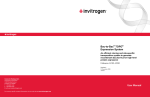
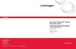
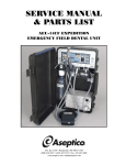
SERVICE MANUAL
& PARTS LIST
AA-75CF
NSN: 6520-01-456-7170 (Part 2 of 2)
For Further Service And/Or Technical Assistance Contact:
Printed In The USA
P.O. Box 1548 Woodinville, WA 98072-1548
1-800-426-5913 * 425-487-3157 * Fax: 425-487-2608
email: [email protected] * Internet: www.aseptico.com
12/98
P/N 420225
P.O. Box 1548 Woodinville, WA 98072-1548
1-800-426-5913 * 425-487-3157 * Fax: 425-487-2608
email: [email protected] * Internet: www.aseptico.com
Notes
TABLE OF CONTENTS
Maintenance and Servicing Instructions . . .3
Table of Illustrations
Cleaning and Lubrication . . . . . . . . . . . . . . . .3
Figure A: AA-75CF
Component Identification . . . . . . . . . . . . . . .5
Performance Verification . . . . . . . . . . . . . . . .3
Inspection . . . . . . . . . . . . . . . . . . . . . . . . . . . .3
Troubleshooting . . . . . . . . . . . . . . . . . . . . . . .3-4
Disassembly, Repair, Replacement,
Reassembly, and Check Out . . . . . . . . . . . . .4-12
Figure B: Compressor Chassis Removal . . .5
Figure Group C: Compressor Removal . . . .6
Figure D: Service Kit Installation . . . . . . . . .7
Figure E: Aftercooler Removal . . . . . . . . . . .9
Compressor Chassis Removal . . . . . . . . . . . .4
Figure F: Pressure Switch Leads . . . . . . . . . .11
Compressor Removal . . . . . . . . . . . . . . . . . . .6
Figure G: Tank Removal . . . . . . . . . . . . . . . .11
Compressor Motor
Service Kit Installation . . . . . . . . . . . . . . . . . .8
Figure H: Intake Fan Removal . . . . . . . . . . .12
Aftercooler Fan Replacement . . . . . . . . . . . .8
Figure J: AA-75CF
System Wiring Schematic . . . . . . . . . . . . . . . .13
Aftercooler Assembly Replacement . . . . . . .9
Pressure Switch Replacement . . . . . . . . . . . .10
Check Valve Replacement . . . . . . . . . . . . . . .10
Removing the Air Storage Tank . . . . . . . . . .10
Replacing Pneumatic Tubing . . . . . . . . . . . . .11
Removing Electronics Module . . . . . . . . . . .12
Removing the Intake Fan . . . . . . . . . . . . . . . .12
Transformer Replacement . . . . . . . . . . . . . . .12
Parts List . . . . . . . . . . . . . . . . . . . . . . . . . . . . .14-26
Case Base . . . . . . . . . . . . . . . . . . . . . . . . . . . . .14
Case Top, Inside . . . . . . . . . . . . . . . . . . . . . . .14
Case Top, Outside . . . . . . . . . . . . . . . . . . . . . .14
Compressor Chassis . . . . . . . . . . . . . . . . . . . .16
Air Storage Tank . . . . . . . . . . . . . . . . . . . . . . .16
Transformer . . . . . . . . . . . . . . . . . . . . . . . . . . .18
Compressor . . . . . . . . . . . . . . . . . . . . . . . . . . .18
Intake Fan . . . . . . . . . . . . . . . . . . . . . . . . . . . .20
Figure I: Electronics Module . . . . . . . . . . . . .12
Figure K: AA-75CF
System Pneumatic Schematic . . . . . . . . . . . .13
Figure 1: Case Base . . . . . . . . . . . . . . . . . . . .15
Figure 2: Case Top, Inside . . . . . . . . . . . . . . .15
Figure 3: Case Top, Outside . . . . . . . . . . . . .15
Figure 4: Compressor Chassis . . . . . . . . . . . .17
Figure 5: Air Storage Tank . . . . . . . . . . . . . . .17
Figure 6: Transformer . . . . . . . . . . . . . . . . . . .19
Figure 7: Compressor . . . . . . . . . . . . . . . . . . .19
Figure 8: Intake Fan . . . . . . . . . . . . . . . . . . . .21
Figure 9: Aftercooler . . . . . . . . . . . . . . . . . . .21
Figure 10: Motor Exhaust Chassis . . . . . . . .23
Figure 11: Electronics Module . . . . . . . . . . .23
Figure 12: Pressure Switch . . . . . . . . . . . . . . .23
Figure 13A & B: Top Cover . . . . . . . . . . . . . .25
Aftercooler . . . . . . . . . . . . . . . . . . . . . . . . . . .20
Motor Exhaust . . . . . . . . . . . . . . . . . . . . . . . . .22
Electronics Module . . . . . . . . . . . . . . . . . . . . .22
Pressure Switch . . . . . . . . . . . . . . . . . . . . . . . .22
Top Cover . . . . . . . . . . . . . . . . . . . . . . . . . . . . .24
Expendables . . . . . . . . . . . . . . . . . . . . . . . . . . .26
Page 2
Page 27
Maintenance and Servicing Instructions
Expendables
ITEM
Cleaning and Lubrication
PART NUMBER
1 Felt, Filter Media
730382
2 Compressor Rebuild Kit
730383
3 Aftercooler Fan Filter Media
730380
4 Intake Fan Filter Media
730381
Exposed surfaces of the AA-75CF should be disinfected with a commercial dental disinfectant.
Abrasive cleaning agents have the potential to damage surface finishes and should be avoided. To
minimize the risk of corrosion do not use chlorinated solvents to clean either the inside or the
outside of the compressor valves, the air storage tank or the aftercooler assembly.
Lubrication of AA-75CF compressor components is unnecessary. The compressor uses sealed
bearings and Teflon cylinder technology to eliminate the need for lubrication. The cooling fans
similarly use sealed bearings.
Performance verification
To verify proper compressor function, make sure the tank gauge pressure is at zero, the tank drain
valve is closed and the pressure switch is in the OFF position. Plug the compressor into the power
source. Switch the pressure switch to the AUTO position. The compressor should charge the air
storage tank and the intake and aftercooler fans should run. Confirm that compressor shut off
occurs at approximately 105 psi. Open the tank drain valve. When gauge pressure in the tank drops
below 70 psi, the compressor should restart. Allow the tank to drain until all significant water is
removed. Once the air exiting the tank is dry to the touch, close the tank drain valve. When
compressor cuts off, verify that the fans continue to run for approximately two minutes and that the
tank pressure remains constant near 100 psi. A 5 psi drop can be expected after cut off. Listen for
leaks at pneumatic system connections. If leaks are indicated by pressure loss but are not audible,
check the seals with a soap test. A water-liquid detergent solution should be applied to the circumference of the joint. A leak at a seal will cause the solution to bubble. Tighten the joint, if necessary
reapply Teflon tape, until bubbles no longer appear.
Inspection
The felt media of the air intake filters requires periodic inspection and replacement. Initial inspection is recommended after 500 hours. Afterwards a service duration should be determined based on
the operating conditions. Excessive felt contamination can reduce compressor output and may affect
service life.
Initial compressor inspection is recommended at 2,000 hours. The wear of the rider ring is an indication of the general condition of the compressor rings. To inspect the rider rings, remove the
compressor from the case as per Compressor Removal instructions, then disassemble the
compressor cylinder heads. If the rider ring measures 0.055 in. or less, an overhaul should be
performed by installing a Service Kit. See the Compressor Motor Service Kit Installation subsection
of the Disassembly, Repair, Replacement, Reassembly and Check Out Section of this manual for
detailed installation procedures.
Troubleshooting
Page 26
Symptom
Problem
Action
System non-operational
Main breaker tripped
Pressure switch contacts corroded
Reset main breaker
Replace switch
Compressor motor not running
Main breaker tripped
Thermal overload tripped
Reset main breaker
Allow several minutes to cool and restart
No duplex outlet power
Circuit breaker tripped
Reset duplex breaker
Tank pressure exceeds 110 psi.
Pressure switch settings altered
Readjust according to Pressure Switch
Replacement section note
Compressor attempts to restart under load
Leaking or obstructed check valve
Misaligned unloader valve
Disassembly and clean or replace.
Tighten unloader valve screw and realign.
Extended compressor cycle time
Air demand has been altered
Clogged intake filters.
Air line leaks.
Water collected in air storage tank.
Readjust instruments
Clean or replace.
Tighten couplings, retape.
Blow off tank
Page 3
Figure 13A Top Cover
Motor won’t start with gauge pressure at 0 psi
The thermal protection of the compressor may have been activated. If system fans are still
functioning, allow the unit to cool briefly and restart. If system fans are not running, a high amperage
condition existed resulting in the system circuit breaker being tripped. This condition will result from
a leaking check valve or malfunctioning unloader valve.
14
24
34
22
11 13
Motor experiences labored start with gauge pressure below 70 psi
This condition results from the motor attempting to restart with pressure in the cylinder. This is an
indication of a leaking check valve or malfunctioning unloader valve. Inspect the check valve and the
unloader switch. Service components as required.
23
15
Motor starts at an intermediate pressure or Pressure relief valve is activated
Disconnect the unit from the power source. Inspect the pressure switch for excessive wear and
damaged or dirty components. Replace parts as required.
9
10
21
Compressor cycles more frequently than is common
Shut off compressor. Watch the tank pressure gauge. If the tank pressure drops rapidly, check tubing
and fittings for leaks. If tubing and fittings are satisfactorily connected, the check valve should be
inspected for dirt and damage. If after shut off tank pressure is maintained, the tank should be blown
off. Water vapor can condense in the tank and reduce its capacity.
25
28
Compressor takes longer to build tank pressure than is common
Check system tubing and fittings for leaks. Inspect compressor air intake filters. Replace filter
cartridge if required.
3
6
4
7
No power to duplex outlet
Verify system is powered. Reset duplex outlet circuit breaker.
Disassembly, Repair, Replacement, Reassembly and Check Out
Figure 13B Top Cover
The AA-75CF has been designed for minimal required maintenance. Compressor service should be
performed every two thousand hours and component service should be required only when component damage occurs or service life is exceeded. Modular construction makes component inspection
and replacement simple. Maintenance can be performed with only the following tools: a 7/16 socket
drive, a set of English Hex wrenches, a 12 in. and an 8 in. crescent wrench, flathead and
#2 Phillips screwdrivers, and a 1/4 inch open face wrench.
12
15
16
17
18
33
1
14
For Reassembly, Teflon tape or an equivalent thread sealant should be applied to all pneumatics
fittings and a serviceable thread locking compound should be applied to all fasteners.
8
9
To check the success of any repair, perform the procedure detailed in the Performance Verification
section.
31
The first step in any major component replacement is the removal of the compressor chassis from
the case bottom.
Compressor Chassis Removal
Tools: 7/16 in. socket wrench and serviceable thread locking compound.
32 33
21
1. Remove case top.
2. Carefully place unit top cover down.
19
3. Remove the case bumper screws, sealing washers and case bumpers. Reference Figure B
20
4. Lift off case bottom. Use a rocking motion to clear ID plate rivets.
5. Replace by reversing steps. Secure case bumper screws using thread locking compound.
5
Page 4
2
30
Page 25
Reference Figures 13A & 13B
ITEM
PART NUMBER
QUANTITY
1 Top Cover
460746-08
1
2 Case Drain Fitting
730337
1
3 Tubing Support Sleeve
730095
1
4 TUBING, Air Brake, 1/4 in.
730130
54 in.
5 FITTING, Needle Valve,
730336
1
1/8 MPT x 1/4 Poly Angle
6 FITTING, Bulkhead mount,
Figure A
AA-75CF Component Identification
Exhaust Baffle
Intake Fan Assembly
Aftercooler Housing Assembly
Pressure Switch
730307
1
7 FITTING, 10-32 x 1/4 Poly
730377
1
8 NUT, Wing, Brass, 1/4-20
Commercial
1
9 STUD, Brass, 1/4-20 x 1 1/2
Commercial
1
10 NUT, Jam, Brass, 1/4-20
Commercial
1
11 Duplex Outlet
840047
1
12 Outlet Cover
850039
1
13 SCREW, Pan head Phillips,
Commercial
2
14 15A Circuit Breaker
830058
1
15 2A Circuit Breaker
830057
1
16 Power Connection Chassis
460798-08
1
17 SCREW, Flat head Phillips,
Commercial
2
Commercial
2
19 Leg Socket
460820-08
4
20 SCREW, Flat head Phillips,
Commercial
4
21 Intake Hose Trim
730378
9.1 in.
22 1/4 Grommet
870185
2
23 5/8 Grommet
870232
1
24 Inlet Wire Set
875010
1
25 Control Wire Set
875012
1
26 Wire Clamp, Steel, Plated
510409
3
27 Wire Clamp, Nylon
510410
1
28 Wire Clamp, Self Adhering
860116
1
29 NUT, Nyloc, Stnl, 8-32
Commercial
4
30 Handle
850041
2
31 Exhaust Baffle
460771-08
1
32 SCREW, Button head socket,
Commercial
10
33 WASHER, int. star, #10, stnl.
Commercial
4
34 Weather Stripping
730394
62 in.
1/8 FPT x 10-32
Compressor
Air Storage Tank Assembly
Stnl, 6-32 x 3/8
Transformer
Electronics Module
Stnl, 6-32 x 3/8
18 SCREW, Button head socket,
Stnl, 10-32 x 3/8
Figure B
Compressor Chassis Removal
Stnl, 10-32 x 3/8
Case Bumper Screws
Stnl, 10-32 x 3/8
Page 24
Page 5
Compressor Removal Reference Figure Group C
Tools: 1/4 and 5/16 hex drive or Allen wrench, flat head screwdriver, 12 in. or smaller crescent wrench, pliers,
and 1/4 open face wrench.
Figure 10 Motor Exhaust Duct
7
8
1. Remove compressor chassis from case bottom as per the Compressor Chassis Removal section.
2. Loosen the duct clamp at on the motor side of the intake hose and remove the hose from the
motor intake.
1
6
5
2
3. Loosen the nut on the motor tee fitting and remove the 1/2 tubing.
3
4. Disconnect the ground wire from under the capacitor cover.
5. Loosen the exhaust duct and twist it free from of the compressor.
6. Disconnect the five insulated terminals from the back of the compressor.
7. Disconnect the two inline connectors.
8. Place the compressor chassis on its right side (motor intake down).
9. Remove the four motor mount bolts.
4
10. Lift the compressor chassis off of the free compressor.
Figure 11 Electronics Module
11. Repair and reassemble by reversing steps. Replace motor connections in their original locations.
See figure C or Figure I System Wiring Diagram. Note: There are two possible terminal locations
at 1 and 5. Either location is acceptable.
Motor Intake
Duct Clamp Location
Motor Tee Fitting
1
Figure Group C
Compressor Removal
2
5
4
Exhaust Duct
3
Motor Mounting Bolts (4)
Figure 12 Pressure Switch
Ground Wire Location
Under Capacitor Cover
2
Inline Connectors and
Insulated Terminals
Brown
7
1
4
Violet
Blue
Black
Orange
6
White
3
Page 6
5
Page 23
Reference Figure 10
ITEM
Figure D
Service Kit Installation
PART NUMBER
QUANTITY
1 Motor Exhaust Chassis
330258
1
2 BOLT, Socket head,
Commercial
1
3 NUT, Nyloc, Stnl, 1/4-20
Commercial
1
4 Motor Wire Set
875011
1
5 Motor Exhaust Strain Relief
840014
1
14
13
Stnl, 1/4-20 x 1 1/4
6 Strain Relief Nut
840015
1
7 Wire Clamp, Steel, Plated
510409
1
8 NUT, Nyloc, Stnl, 8-32
Commercial
1
12
8
10
9
11
18
7
Reference Figure 11
ITEM
1 Electronics Module
2 SCREWS, Button head socket,
6
PART NUMBER
QUANTITY
330253
1
Commercial
2
3 WASHER, #6 Star Stnl.
510419
1
4 NUT, Nylok, Stnl. 6-32
Commercial
1
5 WASHER, int. star, #10, stnl.
Commercial
2
17
5
Reference Figure 12
PART NUMBER
QUANTITY
1 Pressure Switch, 4 Port, Unloader
830052
1
2 7/8 Chrome Snapcap Hole Plug
510210
1
3 5/8 Grommet
870232
1
4 0-160 Pressure Gauge, 1/4 MPT
730136
1
5 FITTING, Quick disconnect,
3/8 Female x 1/4 MPT, w/ shut off
AA-63
1
6 FITTING,
730097
1
1/4 x 1/4 MPT Coupler, Stnl
16
4
3
2
1
Stnl, 10-32 x 3/8
ITEM
ITEM
PART NUMBER
Cylinder Head
Included With Motor
2
*Head Gasket
Service Kit
3
*Outlet Valve
Service Kit
4
Plate Valve
720015
5
*Inlet Valve
Service Kit
6
*Cylinder Gasket
Service Kit
Cylinder
720015
8
*Piston Ring
Service Kit
9
*Piston Seal
Service Kit
Piston Rod Assembly
720015
*Rider Ring
Service Kit
12
Motor Mount Bolt, Nut, Washer
Commercial
1
7
10
11
7 Safety Relief Valve
730196
1
13
Motor
720015
8 WASHER, #8, Ext Star, Stnl
510420
1
14
Motor Tee Fitting
730358
15
Motor Intake Assembly
460784-08
16
Crossover Tube
460777-08
17
Motor Elbow Fitting
730357
*Felt
Service Kit
Service Kit
730383
(Refer to Figure F, Page 11)
15
18
19
* Denotes parts included in the Service Kit.
Page 22
Page 7
Compressor Motor Service Kit Installation Reference Figure D
(Adapted from Gast Operation & Maintenance Technical Manual).
Figure 8 Intake Fan
The compressor motor service kit contains the following: Head Gasket, Valves, Cylinder gasket,
Piston Rings, Piston Seals, Rider Ring, and Felts.
6
1
Dis-Assembly
Tools: 3/16, 1/4, and 5/16 hex drive or Allen wrench, flat head screwdriver, 12 in. or smaller crescent wrench,
pliers, and 1/4 open face wrench.
3
1. Disconnect the compressor from the electrical power.
! CAUTION ! You must disconnect the pump from electrical power before servicing it. Failure to do
so can result in severe personal injury or death.
2
2. Drain the air storage tank and turn the pressure switch to the OFF position.
9
! CAUTION ! You must vent all air lines to the compressor to remove pressure before servicing.
Failure to do so can result in severe personal injury.
7
3. Remove the unit from the case bottom and the compressor from the compressor chassis as
described in the Compressor Chassis removal and Compressor Removal subsections above .
10
8
4. Remove the motor intake and the crossover tube from the compressor.
11
5. Remove the cylinder heads, and valve components. DO NOT re-arrange or reorient the valve
components.
5
4
6. Remove the cylinder and rings.
Make sure all compressor parts are clean before reassembling. DO NOT use any chlorinated
solvents to clean valves, or any liquids to flush units. The stainless steel valves may be cleaned with
water. All parts, except the valves, can be cleaned with any industrial, non-flammable, non-toxic,
non-petroleum based cleaning solvent.
Figure 9 Aftercooler
Assembly
1. Install piston seals, piston rings, and rider ring on each piston.
2. Locate ring joints approximately opposite each other.
13
3. Finger tighten the cylinders to the bracket with the cylinder screws and washers.
1
12
2
4. With the piston in its top dead center position, adjust each cylinder flush with top of piston and
torque cylinder screws to 150-160 inch lbs. Re-torque second time.
5. Stack the valve components in order as originally assembled.
10
6. Install the cylinder head and head screws.
3
11
NOTE: The exhaust ports in the cylinder heads have been marked by omitting the ends of two of the
fins.
8
7. Torque all head screws 150-160 inch lbs.
8. Turn the motor shaft by hand at this point to ensure that the rod assembly is not hitting the head.
NOTE: If rod assembly does hit head, loosen cylinders and re-adjust.
9. Replace the motor intake and crossover tube.
4
9
10. Re-torque head screws again after running for 10 minutes.
Replacing Aftercooler Housing Parts Reference Figure E
Aftercooler Fan Replacement
Tools: 1/8 hex drive or Allen wrench, #2 Phillips screwdriver, 12 in. or smaller crescent wrench, and thread
locking compound.
7
5
6
1. With compressor chassis extracted remove the five aftercooler housing bolts from the top cover.
2. Lift aftercooler housing and disconnect the fan plug.
Page 8
Page 21
Reference Figure 8
Figure E - Aftercooler Removal
ITEM
PART NUMBER
QUANTITY
1
Intake Fan
330259
1
2
Intake Fan Gasket
460779
1
3
SCREW, Button head socket,
Stnl, 10-32 x 5/8
Commercial
2
4
Intake Hose
730339
12 in.
5
HOSE CLAMP, Marine Grade,
1 13/16 - 2 3/4
510400
2
6
Intake Fan Filter Assembly
730334
1
7
BOLT, Flat head Phillips,
Stnl, 6-32 x 1/2
Commercial
4
8
NUT, Nyloc, Stnl, 6-32
Commercial
4
9
1/4 Grommet
870185
1
10 WIRE NUT, Blue
Commercial
2
11 WASHER, #10 Ext Star, Stnl
510421
1
Fan Plug
Push-In Elbow Fitting
Straight Push-In Fitting
Aftercooler Bolts (4)
Release Rings
3. Remove media guard and media from the fan guard assembly.
Reference Figure 9
4. Remove the four aftercooler fan bolts.
5. Replace aftercooler fan and reassemble by reversing steps. Secure aftercooler housing bolts with
thread locking compound.
ITEM
PART NUMBER
QUANTITY
1
Aftercooler Housing
460749-08
1
2
SCREW, Button head socket,
Stnl, 10-32 x 3/8
Commercial
5
Aftercooler Assembly Replacement Reference Figure E
Tools: 1/8 and 3/16 hex drive or Allen wrench, flathead screwdriver, 12 in. or smaller crescent wrench,
serviceable thread locking compound and Teflon tape.
3
Aftercooler Fan
330264
1
1. Remove compressor chassis from case bottom as per the Compressor Chassis Removal section.
4
Aftercooler Fan Filter Assembly
730333
1
5
BOLT, Flat head Phillips, Stnl,
6-32 x 2 1/4
Commercial
4
2. Loosen the nut of the motor tee fitting which secures the motor/aftercooler tube. Remove the
tubing from the motor tee fitting leaving the nut and ferrule on the tube. Reference Figure Group C
6
NUT, Nyloc, Stnl, 6-32
Commercial
4
7
Aftercooler Assembly
330257
1
4. Remove the tank/aftercooler tube from the push-in elbow fitting on the tank by depressing the
release ring and pulling on the tube. Note the tube routing.
8
Aftercooler Cover Plate
460793-08
1
5. Rotate the compressor chassis onto its left side (motor exhaust side). Depress the release ring
9
SCREW, Socket head, Stnl,
1/4-20 x 3/4
Commercial
1
on the push-in straight fitting at aftercooler and pull tube straight out.
730359
1
730361
1
12 TUBING, Air brake, 1/2 in.
730256
18.5 in
13 WASHER, int. star, #10, stnl.
Commercial
3
10 FITTING, Brass, Push-In Elbow,
11 FITTING, Brass, Push-In Straight,
3. Depress the release ring on the aftercooler push-in elbow then pull free the motor/aftercooler
tube previously loosened in step 2.
6. Remove the five aftercooler housing screws, disconnect fan plug and remove aftercooler housing.
1/2 Tube x 1/4 MPT, Viton type
1/2 Tube x 1/4 MPT, Viton type
Page 20
Aftercooler Housing Screws (5)
7. Slide the aftercooler toward the compressor chassis front (power inlet) and remove.
8. Clamp aftercooler block in vise and remove push-in fittings, straight fitting first, then elbow.
Remove aftercooler manifold block screw and aftercooler cover plate. Minimize handling of the
aftercooler to avoid cracking it.
9. Replace aftercooler assembly and reassemble by reversing steps, being careful to reroute tubing
as noted during removal. Seal threaded ends of aftercooler push-in fittings with Teflon tape or
sealing compound and secure aftercooler housing bolts and aftercooler cover plate bolt with a
serviceable thread locking compound.
Page 9
Figure 6 Transformer
Replacing Air Storage Tank Components
Pressure Switch Replacement Reference Figure F
Tools: 1/8 hex drive or Allen wrench, #2 Phillips screw driver, 12 in. or smaller crescent wrench, thread sealing compound or Teflon tape.
1
1. Unplug the AA-75CF compressor and drain the air storage tank.
2
2. Remove compressor chassis from case bottom as per the Compressor Chassis Removal section.
3. Remove four exhaust baffle screws to allow access to the pressure switch screws.
7
4. Loosen pressure switch cover screw and remove pressure switch cover.
5. Loosen the unloader valve nut and remove unloader tube.
6. Loosen screws on the pressure switch to release the motor power leads, the control wire leads and
the switch ground.
3
4
6
When replacing leads, be sure the wire pair leading through the motor exhaust chassis to the motor
connects to the MOTOR location on the pressure switch and that the wire pair from the control wire
set, contained in polyester braid, connects to the LINE location of the pressure switch. Similar wire
colors should attach on the same side of the pressure switch.
5
7. Remove pressure relief valve, female quick connect fitting, and pressure gauge.
8. Using the hex of the coupler fitting, turn pressure switch off of the air storage tank. Guide wires
slowly through the 5/8 grommet during the initial turn.
Figure 7 Compressor
9. Remove the coupler fitting from the pressure switch.
Note: In addition to exposing wire connections, removing the pressure switch cover exposes a pair of
adjustment screws used to control the AA-75 CF compressor’s cut off pressure and pressure range.
By turning the metal screw clockwise the air storage tank cut off pressure is increased. Turning the
plastic screw clockwise increases the separation between the cut off and cut in pressure. Air storage
tank pressure should never be adjusted to exceed 110 psi.
2
4
10. Replace pressure switch and reassemble by reversing steps. Use Teflon tape to seal pipe threaded
fittings.
9
1
8
6
Check Valve Replacement Reference Figure G
Tools: 12 in. or smaller crescent wrench, Teflon tape or thread sealing compound.
1. Remove compressor chassis from case bottom as per the Compressor Chassis Removal section.
2. Loosen nuts on 1/8 poly fittings and disconnect unloader tube and tank side tank drain tube.
7
3. Push in the release ring of the push-in elbow fitting on the tank then pull tank/aftercooler tube
loose.
5
4. Remove push-in elbow fitting and 1/8 tube fitting from the check valve.
3
5. Remove check valve from the air storage tank.
10
6. Replace check valve and reassemble by reversing steps. Use Teflon tape to seal pipe threaded
fittings.
Removing the Air Storage Tank Reference Figure G
11
13
12
1. Remove compressor chassis from case bottom as per the Compressor Chassis Removal section.
2. Complete Pressure Switch Replacement procedure omitting steps 7, 9 and 10.
3. Complete Check Valve Replacement procedure omitting steps 4 and 6.
4. Remove three tank assembly screws and the 1/8 tube fitting on the tank bottom.
5. Rotate the air storage tank slowly clockwise and remove through the exhaust duct side of the
compressor chassis leading with the tank bottom.
Page 10
Page 19
Figure F
Pressure Switch Leads
Reference Figure 6
ITEM
PART NUMBER
QUANTITY
1
Transformer Assembly
875013
1
2
Transformer Bracket
460818-04
2
3
BOLT, Pan head Phillips,
Stnl, 10-32 x 2
Commercial
4
4
NUT, Nylok, Stnl, 10-32
Commercial
4
5
SCREW, Button head socket,
Stnl, 10-32 x 3/8
Commercial
4
6
WASHER, nylon, 0.062 thk
510019
2
7
WASHER, int. star, #10, stnl.
Commercial
6
Peak Pressure Adjustment
Unloader Valve Nut
Motor Wire Connections
Control Wire Connections
Figure G
Tank Removal
Star Washer
Tank Assembly Screws
Reference Figure 7
ITEM
PART NUMBER
QUANTITY
1
Compressor
720015
1
2
Motor Intake
460784-08
1
3
Crossover Tube
460777-08
1
4
FITTING, A/B branch tee,
1/2 tube x 1/4 MPT
730358
1
5
FITTING, A/B Male Elbow,
3/8 tube x 1/4 MPT
730357
1
6
FITTING, Plug,
1/4 MPT x 1/4 Hex countersink
730098
2
7
FITTING, 45 deg.,
1/4 Flare x 1/4 MPT
730200
2
8
HOSE CLAMP, Marine grade,
7/16 - 25/32, Miniature width
510416
4
9
TUBING, 1/2” I.D. x 0.063 wall
AA-83A
1 in.
Commercial
4
11 WASHER, Mil. Spec. 15795-812
Commercial
4
12 NUT, Nyloc, Stnl, 5/16-18
Commercial
4
3. Select the correct tubing size and cut to the appropriate length:
13 WASHER, int star, #8, stnl
510420
1
Motor / Aftercooler tube
10 BOLT, Socket head, Stnl,
Compressor Cut-In/Cut-Off
Pressure Differential Adjustment
Check Valve
1/8 Tube Fittings
Push-In Elbow Fitting
Replacing Pneumatic Tubing
1. Loosen tube at both ends by depressing the push-in fitting release ring then the tube free or by
removing the fitting nut.
5/16-18 x 1 1/2
2. Note the ferrule type on both ends of the tube then discard tube section and attached ferrules.
Tank / Aftercooler tube
13.0 in.
8.1 in.
Unloader tube
10.0 in.
Case side tank drain tube
15.0 in.
Tank side tank drain tube
24.0 in.
Case drain tube
15.5 in.
4. Slide the fitting nut and the appropriate new ferrule onto the tube and re-attach. When replacing
tubing routed to the aftercooler, make aftercooler connections first.
Page 18
Page 11
Removing the Electronics Module Reference Figure I
Tools: 1/8 hex drive or Allen wrench and serviceable thread locking compound.
Figure 4 Compressor Chassis
1. Remove compressor chassis from case bottom.
2. Uncouple control wire set connector and motor wire set connector.
12
11
3. Remove the two electronics mounting screws.
4. Reattach by reversing steps. Install fasteners using a serviceable thread locking compound.
Figure H Intake Fan Removal
Wire Nuts
Figure I Electronics Module
Intake Fan Screws
(one shown- second opposite 180 deg.)
18
13
16
Motor Wire Set
Connector
14
8
7
9
6
Electrical Cover
2
3
1
Transformer Bracket
Screws & Star Washers
Transformer Wire
Set Connectors
5
Control Wire
Set Connector
4
Elec. Mounting Screws
15
10
17
Removing the Intake Fan Reference Figure H
Tools: 1/8 hex drive or Allen wrench, flat head screwdriver, side cutters and serviceable thread
locking compound.
1. Remove compressor chassis as per the Compressor Chassis Removal section.
2. Remove the 9 perimeter screws of the top cover.
3. Remove pneumatic tubing at tank elbow push-in fitting, motor tee fitting and tank drain poly
fitting.
4. Lift off the top cover.
5. Remove the electrical cover on the fan motor to expose the electrical connections
6. Remove the two wire nuts and pull the two wire pairs through the 1/4 grommet.
7. Remove the two intake fan screws located on the underside of the top cover.
8. Remove the fan motor being careful not to bend the impeller.
9. Replace intake fan and reattach by reversing steps. Install fasteners using a serviceable thread
locking compound. Strip wires 1/4 in. and reconnect using wire nuts. Connect one orange and one
purple wire to each black fan lead. Individual wire orientation is not critical.
Figure 5 Air Storage Tank
1
6
2
Transformer Replacement Reference Figure I
Tools: 1/8 hex drive or Allen wrench and thread locking compound.
1. Remove compressor chassis from case bottom.
2. Uncouple the connector between the transformer and the electronics box.
3. Remove the four transformer bracket screws.
4. Replace and reassemble by reversing steps. Apply thread locking compound to screws when
installing. Be sure star washers are replaced under the bolt heads contacting the brackets and
between the brackets and the chassis base.
Note: To check the success of any repair perform the procedure detailed in the Verification section.
Page 12
4
3
5
Page 17
AA-75CF SYSTEM WIRING SCHEMATIC
Reference Figure 4
ITEM
PART NUMBER
QUANTITY
1
Chassis Base
330260
1
2
Vibration Isolator
730314
3
3
SCREW, Flathead Phillips,
Stnl, 1/4-20 x 1/2
Commercial
6
4
Chassis Corner Bracket
330261
4
5
Motor Mount
330255-08
1
6
NUT, Serrated flange, Stnl, 5/16-18
Commercial
4
7
WASHER, Mil. Spec. 15795-812
Commercial
4
8
BOLT, Hex head, Stnl, 5/16-18 x 2
Commercial
4
9
Chassis Corner Angle
460747-08
3
10 Chassis Side Angle
460748-08
1
11 Chassis Cover Channel, Front
460787-08
1
12 Chassis Cover Channel, Left
460788-08
1
13 Chassis Cover Channel, Back
460789-08
1
14 Chassis Cover Channel, Right
460770-08
1
15 SCREW, Button head socket,
Commercial
24
Commercial
16
17 WASHER, int. star, #10, stnl.
Commercial
24
18 WASHER, int. star, #8, stnl.
Commercial
16
Figure J
Stnl, 10-32 x 3/8
16 SCREW, Button head socket,
8-32 x 3/8
Reference Figure 5
Page 16
ITEM
PART NUMBER
QUANTITY
1
Air Storage Tank
330254-08
1
2
Check Valve
730332
1
3
FITTING, Brass, Push-In Elbow,
1/2 Tube x 1/4 MPT, Viton type
730359
1
4
FITTING, Brass,
1/4 Poly x 1/8 MPT
730117
2
5
TUBING, Air Brake, 1/4
730130
12.5 in.
6
SCREW, Button head socket,
Stnl, 10-32 x 3/8
Commercial
3
7
WASHER, int. star, #10, stnl.
Commercial
3
AA-75CF SYSTEM PNEUMATIC SCHEMATIC
Figure K
Page 13
PARTS LIST
Figure 1 Case Base
5
1
4
Reference Figure 1
ITEM
PART NUMBER
QUANTITY
1
Case, Mil. Spec., Bottom
410128
1
2
Identification Plate, Case
420229
1
3
Weather stripping
730375
63in.
4
Case Bumper
730109
4
5
SCREW, Hex head,Stnl,
1/4-20 x 1 1/4
Commercial
4
3
2
Figure 2 Case Top - Inside
2
1
3
5
Reference Figures 2 & 3
ITEM
8
PART NUMBER
QUANTITY
1 Case, Mil. Spec., Top
410128
1
2 Case Leg
460776-08
2
3 Case Leg Pivot
460802-08
4
4 Case Leg Bumper
460828
4
5 NUT, Nylok, Stnl, 10-32
Commercial
4
6 230V Power cord
840007
1
7 120V Power cord
840049
1
8 Cord Pouch
460649-08
1
9 BOLT, Button head socket,
Commercial
4
10 Washer, Sealing, Stnl, #10
510353
4
Stnl,10-32 x 5/8
4
6
7
Figure 3 Case Top - Outside
9
10
Page 14
Page 15
AA-75CF SYSTEM WIRING SCHEMATIC
Reference Figure 4
ITEM
PART NUMBER
QUANTITY
1
Chassis Base
330260
1
2
Vibration Isolator
730314
3
3
SCREW, Flathead Phillips,
Stnl, 1/4-20 x 1/2
Commercial
6
4
Chassis Corner Bracket
330261
4
5
Motor Mount
330255-08
1
6
NUT, Serrated flange, Stnl, 5/16-18
Commercial
4
7
WASHER, Mil. Spec. 15795-812
Commercial
4
8
BOLT, Hex head, Stnl, 5/16-18 x 2
Commercial
4
9
Chassis Corner Angle
460747-08
3
10 Chassis Side Angle
460748-08
1
11 Chassis Cover Channel, Front
460787-08
1
12 Chassis Cover Channel, Left
460788-08
1
13 Chassis Cover Channel, Back
460789-08
1
14 Chassis Cover Channel, Right
460770-08
1
15 SCREW, Button head socket,
Commercial
24
Commercial
16
17 WASHER, int. star, #10, stnl.
Commercial
24
18 WASHER, int. star, #8, stnl.
Commercial
16
Figure J
Stnl, 10-32 x 3/8
16 SCREW, Button head socket,
8-32 x 3/8
Reference Figure 5
Page 16
ITEM
PART NUMBER
QUANTITY
1
Air Storage Tank
330254-08
1
2
Check Valve
730332
1
3
FITTING, Brass, Push-In Elbow,
1/2 Tube x 1/4 MPT, Viton type
730359
1
4
FITTING, Brass,
1/4 Poly x 1/8 MPT
730117
2
5
TUBING, Air Brake, 1/4
730130
12.5 in.
6
SCREW, Button head socket,
Stnl, 10-32 x 3/8
Commercial
3
7
WASHER, int. star, #10, stnl.
Commercial
3
AA-75CF SYSTEM PNEUMATIC SCHEMATIC
Figure K
Page 13
Removing the Electronics Module Reference Figure I
Tools: 1/8 hex drive or Allen wrench and serviceable thread locking compound.
Figure 4 Compressor Chassis
1. Remove compressor chassis from case bottom.
2. Uncouple control wire set connector and motor wire set connector.
12
11
3. Remove the two electronics mounting screws.
4. Reattach by reversing steps. Install fasteners using a serviceable thread locking compound.
Figure H Intake Fan Removal
Wire Nuts
Figure I Electronics Module
Intake Fan Screws
(one shown- second opposite 180 deg.)
18
13
16
Motor Wire Set
Connector
14
8
7
9
6
Electrical Cover
2
3
1
Transformer Bracket
Screws & Star Washers
Transformer Wire
Set Connectors
5
Control Wire
Set Connector
4
Elec. Mounting Screws
15
10
17
Removing the Intake Fan Reference Figure H
Tools: 1/8 hex drive or Allen wrench, flat head screwdriver, side cutters and serviceable thread
locking compound.
1. Remove compressor chassis as per the Compressor Chassis Removal section.
2. Remove the 9 perimeter screws of the top cover.
3. Remove pneumatic tubing at tank elbow push-in fitting, motor tee fitting and tank drain poly
fitting.
4. Lift off the top cover.
5. Remove the electrical cover on the fan motor to expose the electrical connections
6. Remove the two wire nuts and pull the two wire pairs through the 1/4 grommet.
7. Remove the two intake fan screws located on the underside of the top cover.
8. Remove the fan motor being careful not to bend the impeller.
9. Replace intake fan and reattach by reversing steps. Install fasteners using a serviceable thread
locking compound. Strip wires 1/4 in. and reconnect using wire nuts. Connect one orange and one
purple wire to each black fan lead. Individual wire orientation is not critical.
Figure 5 Air Storage Tank
1
6
2
Transformer Replacement Reference Figure I
Tools: 1/8 hex drive or Allen wrench and thread locking compound.
1. Remove compressor chassis from case bottom.
2. Uncouple the connector between the transformer and the electronics box.
3. Remove the four transformer bracket screws.
4. Replace and reassemble by reversing steps. Apply thread locking compound to screws when
installing. Be sure star washers are replaced under the bolt heads contacting the brackets and
between the brackets and the chassis base.
Note: To check the success of any repair perform the procedure detailed in the Verification section.
Page 12
4
3
5
Page 17
Figure F
Pressure Switch Leads
Reference Figure 6
ITEM
PART NUMBER
QUANTITY
1
Transformer Assembly
875013
1
2
Transformer Bracket
460818-04
2
3
BOLT, Pan head Phillips,
Stnl, 10-32 x 2
Commercial
4
4
NUT, Nylok, Stnl, 10-32
Commercial
4
5
SCREW, Button head socket,
Stnl, 10-32 x 3/8
Commercial
4
6
WASHER, nylon, 0.062 thk
510019
2
7
WASHER, int. star, #10, stnl.
Commercial
6
Peak Pressure Adjustment
Unloader Valve Nut
Motor Wire Connections
Control Wire Connections
Figure G
Tank Removal
Star Washer
Tank Assembly Screws
Reference Figure 7
ITEM
PART NUMBER
QUANTITY
1
Compressor
720015
1
2
Motor Intake
460784-08
1
3
Crossover Tube
460777-08
1
4
FITTING, A/B branch tee,
1/2 tube x 1/4 MPT
730358
1
5
FITTING, A/B Male Elbow,
3/8 tube x 1/4 MPT
730357
1
6
FITTING, Plug,
1/4 MPT x 1/4 Hex countersink
730098
2
7
FITTING, 45 deg.,
1/4 Flare x 1/4 MPT
730200
2
8
HOSE CLAMP, Marine grade,
7/16 - 25/32, Miniature width
510416
4
9
TUBING, 1/2” I.D. x 0.063 wall
AA-83A
1 in.
Commercial
4
11 WASHER, Mil. Spec. 15795-812
Commercial
4
12 NUT, Nyloc, Stnl, 5/16-18
Commercial
4
3. Select the correct tubing size and cut to the appropriate length:
13 WASHER, int star, #8, stnl
510420
1
Motor / Aftercooler tube
10 BOLT, Socket head, Stnl,
Compressor Cut-In/Cut-Off
Pressure Differential Adjustment
Check Valve
1/8 Tube Fittings
Push-In Elbow Fitting
Replacing Pneumatic Tubing
1. Loosen tube at both ends by depressing the push-in fitting release ring then the tube free or by
removing the fitting nut.
5/16-18 x 1 1/2
2. Note the ferrule type on both ends of the tube then discard tube section and attached ferrules.
Tank / Aftercooler tube
13.0 in.
8.1 in.
Unloader tube
10.0 in.
Case side tank drain tube
15.0 in.
Tank side tank drain tube
24.0 in.
Case drain tube
15.5 in.
4. Slide the fitting nut and the appropriate new ferrule onto the tube and re-attach. When replacing
tubing routed to the aftercooler, make aftercooler connections first.
Page 18
Page 11
Figure 6 Transformer
Replacing Air Storage Tank Components
Pressure Switch Replacement Reference Figure F
Tools: 1/8 hex drive or Allen wrench, #2 Phillips screw driver, 12 in. or smaller crescent wrench, thread sealing compound or Teflon tape.
1
1. Unplug the AA-75CF compressor and drain the air storage tank.
2
2. Remove compressor chassis from case bottom as per the Compressor Chassis Removal section.
3. Remove four exhaust baffle screws to allow access to the pressure switch screws.
7
4. Loosen pressure switch cover screw and remove pressure switch cover.
5. Loosen the unloader valve nut and remove unloader tube.
6. Loosen screws on the pressure switch to release the motor power leads, the control wire leads and
the switch ground.
3
4
6
When replacing leads, be sure the wire pair leading through the motor exhaust chassis to the motor
connects to the MOTOR location on the pressure switch and that the wire pair from the control wire
set, contained in polyester braid, connects to the LINE location of the pressure switch. Similar wire
colors should attach on the same side of the pressure switch.
5
7. Remove pressure relief valve, female quick connect fitting, and pressure gauge.
8. Using the hex of the coupler fitting, turn pressure switch off of the air storage tank. Guide wires
slowly through the 5/8 grommet during the initial turn.
Figure 7 Compressor
9. Remove the coupler fitting from the pressure switch.
Note: In addition to exposing wire connections, removing the pressure switch cover exposes a pair of
adjustment screws used to control the AA-75 CF compressor’s cut off pressure and pressure range.
By turning the metal screw clockwise the air storage tank cut off pressure is increased. Turning the
plastic screw clockwise increases the separation between the cut off and cut in pressure. Air storage
tank pressure should never be adjusted to exceed 110 psi.
2
4
10. Replace pressure switch and reassemble by reversing steps. Use Teflon tape to seal pipe threaded
fittings.
9
1
8
6
Check Valve Replacement Reference Figure G
Tools: 12 in. or smaller crescent wrench, Teflon tape or thread sealing compound.
1. Remove compressor chassis from case bottom as per the Compressor Chassis Removal section.
2. Loosen nuts on 1/8 poly fittings and disconnect unloader tube and tank side tank drain tube.
7
3. Push in the release ring of the push-in elbow fitting on the tank then pull tank/aftercooler tube
loose.
5
4. Remove push-in elbow fitting and 1/8 tube fitting from the check valve.
3
5. Remove check valve from the air storage tank.
10
6. Replace check valve and reassemble by reversing steps. Use Teflon tape to seal pipe threaded
fittings.
Removing the Air Storage Tank Reference Figure G
11
13
12
1. Remove compressor chassis from case bottom as per the Compressor Chassis Removal section.
2. Complete Pressure Switch Replacement procedure omitting steps 7, 9 and 10.
3. Complete Check Valve Replacement procedure omitting steps 4 and 6.
4. Remove three tank assembly screws and the 1/8 tube fitting on the tank bottom.
5. Rotate the air storage tank slowly clockwise and remove through the exhaust duct side of the
compressor chassis leading with the tank bottom.
Page 10
Page 19
Reference Figure 8
Figure E - Aftercooler Removal
ITEM
PART NUMBER
QUANTITY
1
Intake Fan
330259
1
2
Intake Fan Gasket
460779
1
3
SCREW, Button head socket,
Stnl, 10-32 x 5/8
Commercial
2
4
Intake Hose
730339
12 in.
5
HOSE CLAMP, Marine Grade,
1 13/16 - 2 3/4
510400
2
6
Intake Fan Filter Assembly
730334
1
7
BOLT, Flat head Phillips,
Stnl, 6-32 x 1/2
Commercial
4
8
NUT, Nyloc, Stnl, 6-32
Commercial
4
9
1/4 Grommet
870185
1
10 WIRE NUT, Blue
Commercial
2
11 WASHER, #10 Ext Star, Stnl
510421
1
Fan Plug
Push-In Elbow Fitting
Straight Push-In Fitting
Aftercooler Bolts (4)
Release Rings
3. Remove media guard and media from the fan guard assembly.
Reference Figure 9
4. Remove the four aftercooler fan bolts.
5. Replace aftercooler fan and reassemble by reversing steps. Secure aftercooler housing bolts with
thread locking compound.
ITEM
PART NUMBER
QUANTITY
1
Aftercooler Housing
460749-08
1
2
SCREW, Button head socket,
Stnl, 10-32 x 3/8
Commercial
5
Aftercooler Assembly Replacement Reference Figure E
Tools: 1/8 and 3/16 hex drive or Allen wrench, flathead screwdriver, 12 in. or smaller crescent wrench,
serviceable thread locking compound and Teflon tape.
3
Aftercooler Fan
330264
1
1. Remove compressor chassis from case bottom as per the Compressor Chassis Removal section.
4
Aftercooler Fan Filter Assembly
730333
1
5
BOLT, Flat head Phillips, Stnl,
6-32 x 2 1/4
Commercial
4
2. Loosen the nut of the motor tee fitting which secures the motor/aftercooler tube. Remove the
tubing from the motor tee fitting leaving the nut and ferrule on the tube. Reference Figure Group C
6
NUT, Nyloc, Stnl, 6-32
Commercial
4
7
Aftercooler Assembly
330257
1
4. Remove the tank/aftercooler tube from the push-in elbow fitting on the tank by depressing the
release ring and pulling on the tube. Note the tube routing.
8
Aftercooler Cover Plate
460793-08
1
5. Rotate the compressor chassis onto its left side (motor exhaust side). Depress the release ring
9
SCREW, Socket head, Stnl,
1/4-20 x 3/4
Commercial
1
on the push-in straight fitting at aftercooler and pull tube straight out.
730359
1
730361
1
12 TUBING, Air brake, 1/2 in.
730256
18.5 in
13 WASHER, int. star, #10, stnl.
Commercial
3
10 FITTING, Brass, Push-In Elbow,
11 FITTING, Brass, Push-In Straight,
3. Depress the release ring on the aftercooler push-in elbow then pull free the motor/aftercooler
tube previously loosened in step 2.
6. Remove the five aftercooler housing screws, disconnect fan plug and remove aftercooler housing.
1/2 Tube x 1/4 MPT, Viton type
1/2 Tube x 1/4 MPT, Viton type
Page 20
Aftercooler Housing Screws (5)
7. Slide the aftercooler toward the compressor chassis front (power inlet) and remove.
8. Clamp aftercooler block in vise and remove push-in fittings, straight fitting first, then elbow.
Remove aftercooler manifold block screw and aftercooler cover plate. Minimize handling of the
aftercooler to avoid cracking it.
9. Replace aftercooler assembly and reassemble by reversing steps, being careful to reroute tubing
as noted during removal. Seal threaded ends of aftercooler push-in fittings with Teflon tape or
sealing compound and secure aftercooler housing bolts and aftercooler cover plate bolt with a
serviceable thread locking compound.
Page 9
Compressor Motor Service Kit Installation Reference Figure D
(Adapted from Gast Operation & Maintenance Technical Manual).
Figure 8 Intake Fan
The compressor motor service kit contains the following: Head Gasket, Valves, Cylinder gasket,
Piston Rings, Piston Seals, Rider Ring, and Felts.
6
1
Dis-Assembly
Tools: 3/16, 1/4, and 5/16 hex drive or Allen wrench, flat head screwdriver, 12 in. or smaller crescent wrench,
pliers, and 1/4 open face wrench.
3
1. Disconnect the compressor from the electrical power.
! CAUTION ! You must disconnect the pump from electrical power before servicing it. Failure to do
so can result in severe personal injury or death.
2
2. Drain the air storage tank and turn the pressure switch to the OFF position.
9
! CAUTION ! You must vent all air lines to the compressor to remove pressure before servicing.
Failure to do so can result in severe personal injury.
7
3. Remove the unit from the case bottom and the compressor from the compressor chassis as
described in the Compressor Chassis removal and Compressor Removal subsections above .
10
8
4. Remove the motor intake and the crossover tube from the compressor.
11
5. Remove the cylinder heads, and valve components. DO NOT re-arrange or reorient the valve
components.
5
4
6. Remove the cylinder and rings.
Make sure all compressor parts are clean before reassembling. DO NOT use any chlorinated
solvents to clean valves, or any liquids to flush units. The stainless steel valves may be cleaned with
water. All parts, except the valves, can be cleaned with any industrial, non-flammable, non-toxic,
non-petroleum based cleaning solvent.
Figure 9 Aftercooler
Assembly
1. Install piston seals, piston rings, and rider ring on each piston.
2. Locate ring joints approximately opposite each other.
13
3. Finger tighten the cylinders to the bracket with the cylinder screws and washers.
1
12
2
4. With the piston in its top dead center position, adjust each cylinder flush with top of piston and
torque cylinder screws to 150-160 inch lbs. Re-torque second time.
5. Stack the valve components in order as originally assembled.
10
6. Install the cylinder head and head screws.
3
11
NOTE: The exhaust ports in the cylinder heads have been marked by omitting the ends of two of the
fins.
8
7. Torque all head screws 150-160 inch lbs.
8. Turn the motor shaft by hand at this point to ensure that the rod assembly is not hitting the head.
NOTE: If rod assembly does hit head, loosen cylinders and re-adjust.
9. Replace the motor intake and crossover tube.
4
9
10. Re-torque head screws again after running for 10 minutes.
Replacing Aftercooler Housing Parts Reference Figure E
Aftercooler Fan Replacement
Tools: 1/8 hex drive or Allen wrench, #2 Phillips screwdriver, 12 in. or smaller crescent wrench, and thread
locking compound.
7
5
6
1. With compressor chassis extracted remove the five aftercooler housing bolts from the top cover.
2. Lift aftercooler housing and disconnect the fan plug.
Page 8
Page 21
Reference Figure 10
ITEM
Figure D
Service Kit Installation
PART NUMBER
QUANTITY
1 Motor Exhaust Chassis
330258
1
2 BOLT, Socket head,
Commercial
1
3 NUT, Nyloc, Stnl, 1/4-20
Commercial
1
4 Motor Wire Set
875011
1
5 Motor Exhaust Strain Relief
840014
1
14
13
Stnl, 1/4-20 x 1 1/4
6 Strain Relief Nut
840015
1
7 Wire Clamp, Steel, Plated
510409
1
8 NUT, Nyloc, Stnl, 8-32
Commercial
1
12
8
10
9
11
18
7
Reference Figure 11
ITEM
1 Electronics Module
2 SCREWS, Button head socket,
6
PART NUMBER
QUANTITY
330253
1
Commercial
2
3 WASHER, #6 Star Stnl.
510419
1
4 NUT, Nylok, Stnl. 6-32
Commercial
1
5 WASHER, int. star, #10, stnl.
Commercial
2
17
5
Reference Figure 12
PART NUMBER
QUANTITY
1 Pressure Switch, 4 Port, Unloader
830052
1
2 7/8 Chrome Snapcap Hole Plug
510210
1
3 5/8 Grommet
870232
1
4 0-160 Pressure Gauge, 1/4 MPT
730136
1
5 FITTING, Quick disconnect,
3/8 Female x 1/4 MPT, w/ shut off
AA-63
1
6 FITTING,
730097
1
1/4 x 1/4 MPT Coupler, Stnl
16
4
3
2
1
Stnl, 10-32 x 3/8
ITEM
ITEM
PART NUMBER
Cylinder Head
Included With Motor
2
*Head Gasket
Service Kit
3
*Outlet Valve
Service Kit
4
Plate Valve
720015
5
*Inlet Valve
Service Kit
6
*Cylinder Gasket
Service Kit
Cylinder
720015
8
*Piston Ring
Service Kit
9
*Piston Seal
Service Kit
Piston Rod Assembly
720015
*Rider Ring
Service Kit
12
Motor Mount Bolt, Nut, Washer
Commercial
1
7
10
11
7 Safety Relief Valve
730196
1
13
Motor
720015
8 WASHER, #8, Ext Star, Stnl
510420
1
14
Motor Tee Fitting
730358
15
Motor Intake Assembly
460784-08
16
Crossover Tube
460777-08
17
Motor Elbow Fitting
730357
*Felt
Service Kit
Service Kit
730383
(Refer to Figure F, Page 11)
15
18
19
* Denotes parts included in the Service Kit.
Page 22
Page 7
Compressor Removal Reference Figure Group C
Tools: 1/4 and 5/16 hex drive or Allen wrench, flat head screwdriver, 12 in. or smaller crescent wrench, pliers,
and 1/4 open face wrench.
Figure 10 Motor Exhaust Duct
7
8
1. Remove compressor chassis from case bottom as per the Compressor Chassis Removal section.
2. Loosen the duct clamp at on the motor side of the intake hose and remove the hose from the
motor intake.
1
6
5
2
3. Loosen the nut on the motor tee fitting and remove the 1/2 tubing.
3
4. Disconnect the ground wire from under the capacitor cover.
5. Loosen the exhaust duct and twist it free from of the compressor.
6. Disconnect the five insulated terminals from the back of the compressor.
7. Disconnect the two inline connectors.
8. Place the compressor chassis on its right side (motor intake down).
9. Remove the four motor mount bolts.
4
10. Lift the compressor chassis off of the free compressor.
Figure 11 Electronics Module
11. Repair and reassemble by reversing steps. Replace motor connections in their original locations.
See figure C or Figure I System Wiring Diagram. Note: There are two possible terminal locations
at 1 and 5. Either location is acceptable.
Motor Intake
Duct Clamp Location
Motor Tee Fitting
1
Figure Group C
Compressor Removal
2
5
4
Exhaust Duct
3
Motor Mounting Bolts (4)
Figure 12 Pressure Switch
Ground Wire Location
Under Capacitor Cover
2
Inline Connectors and
Insulated Terminals
Brown
7
1
4
Violet
Blue
Black
Orange
6
White
3
Page 6
5
Page 23
Reference Figures 13A & 13B
ITEM
PART NUMBER
QUANTITY
1 Top Cover
460746-08
1
2 Case Drain Fitting
730337
1
3 Tubing Support Sleeve
730095
1
4 TUBING, Air Brake, 1/4 in.
730130
54 in.
5 FITTING, Needle Valve,
730336
1
1/8 MPT x 1/4 Poly Angle
6 FITTING, Bulkhead mount,
Figure A
AA-75CF Component Identification
Exhaust Baffle
Intake Fan Assembly
Aftercooler Housing Assembly
Pressure Switch
730307
1
7 FITTING, 10-32 x 1/4 Poly
730377
1
8 NUT, Wing, Brass, 1/4-20
Commercial
1
9 STUD, Brass, 1/4-20 x 1 1/2
Commercial
1
10 NUT, Jam, Brass, 1/4-20
Commercial
1
11 Duplex Outlet
840047
1
12 Outlet Cover
850039
1
13 SCREW, Pan head Phillips,
Commercial
2
14 15A Circuit Breaker
830058
1
15 2A Circuit Breaker
830057
1
16 Power Connection Chassis
460798-08
1
17 SCREW, Flat head Phillips,
Commercial
2
Commercial
2
19 Leg Socket
460820-08
4
20 SCREW, Flat head Phillips,
Commercial
4
21 Intake Hose Trim
730378
9.1 in.
22 1/4 Grommet
870185
2
23 5/8 Grommet
870232
1
24 Inlet Wire Set
875010
1
25 Control Wire Set
875012
1
26 Wire Clamp, Steel, Plated
510409
3
27 Wire Clamp, Nylon
510410
1
28 Wire Clamp, Self Adhering
860116
1
29 NUT, Nyloc, Stnl, 8-32
Commercial
4
30 Handle
850041
2
31 Exhaust Baffle
460771-08
1
32 SCREW, Button head socket,
Commercial
10
33 WASHER, int. star, #10, stnl.
Commercial
4
34 Weather Stripping
730394
62 in.
1/8 FPT x 10-32
Compressor
Air Storage Tank Assembly
Stnl, 6-32 x 3/8
Transformer
Electronics Module
Stnl, 6-32 x 3/8
18 SCREW, Button head socket,
Stnl, 10-32 x 3/8
Figure B
Compressor Chassis Removal
Stnl, 10-32 x 3/8
Case Bumper Screws
Stnl, 10-32 x 3/8
Page 24
Page 5
Figure 13A Top Cover
Motor won’t start with gauge pressure at 0 psi
The thermal protection of the compressor may have been activated. If system fans are still
functioning, allow the unit to cool briefly and restart. If system fans are not running, a high amperage
condition existed resulting in the system circuit breaker being tripped. This condition will result from
a leaking check valve or malfunctioning unloader valve.
14
24
34
22
11 13
Motor experiences labored start with gauge pressure below 70 psi
This condition results from the motor attempting to restart with pressure in the cylinder. This is an
indication of a leaking check valve or malfunctioning unloader valve. Inspect the check valve and the
unloader switch. Service components as required.
23
15
Motor starts at an intermediate pressure or Pressure relief valve is activated
Disconnect the unit from the power source. Inspect the pressure switch for excessive wear and
damaged or dirty components. Replace parts as required.
9
10
21
Compressor cycles more frequently than is common
Shut off compressor. Watch the tank pressure gauge. If the tank pressure drops rapidly, check tubing
and fittings for leaks. If tubing and fittings are satisfactorily connected, the check valve should be
inspected for dirt and damage. If after shut off tank pressure is maintained, the tank should be blown
off. Water vapor can condense in the tank and reduce its capacity.
25
28
Compressor takes longer to build tank pressure than is common
Check system tubing and fittings for leaks. Inspect compressor air intake filters. Replace filter
cartridge if required.
3
6
4
7
No power to duplex outlet
Verify system is powered. Reset duplex outlet circuit breaker.
Disassembly, Repair, Replacement, Reassembly and Check Out
Figure 13B Top Cover
The AA-75CF has been designed for minimal required maintenance. Compressor service should be
performed every two thousand hours and component service should be required only when component damage occurs or service life is exceeded. Modular construction makes component inspection
and replacement simple. Maintenance can be performed with only the following tools: a 7/16 socket
drive, a set of English Hex wrenches, a 12 in. and an 8 in. crescent wrench, flathead and
#2 Phillips screwdrivers, and a 1/4 inch open face wrench.
12
15
16
17
18
33
1
14
For Reassembly, Teflon tape or an equivalent thread sealant should be applied to all pneumatics
fittings and a serviceable thread locking compound should be applied to all fasteners.
8
9
To check the success of any repair, perform the procedure detailed in the Performance Verification
section.
31
The first step in any major component replacement is the removal of the compressor chassis from
the case bottom.
Compressor Chassis Removal
Tools: 7/16 in. socket wrench and serviceable thread locking compound.
32 33
21
1. Remove case top.
2. Carefully place unit top cover down.
19
3. Remove the case bumper screws, sealing washers and case bumpers. Reference Figure B
20
4. Lift off case bottom. Use a rocking motion to clear ID plate rivets.
5. Replace by reversing steps. Secure case bumper screws using thread locking compound.
5
Page 4
2
30
Page 25
Maintenance and Servicing Instructions
Expendables
ITEM
Cleaning and Lubrication
PART NUMBER
1 Felt, Filter Media
730382
2 Compressor Rebuild Kit
730383
3 Aftercooler Fan Filter Media
730380
4 Intake Fan Filter Media
730381
Exposed surfaces of the AA-75CF should be disinfected with a commercial dental disinfectant.
Abrasive cleaning agents have the potential to damage surface finishes and should be avoided. To
minimize the risk of corrosion do not use chlorinated solvents to clean either the inside or the
outside of the compressor valves, the air storage tank or the aftercooler assembly.
Lubrication of AA-75CF compressor components is unnecessary. The compressor uses sealed
bearings and Teflon cylinder technology to eliminate the need for lubrication. The cooling fans
similarly use sealed bearings.
Performance verification
To verify proper compressor function, make sure the tank gauge pressure is at zero, the tank drain
valve is closed and the pressure switch is in the OFF position. Plug the compressor into the power
source. Switch the pressure switch to the AUTO position. The compressor should charge the air
storage tank and the intake and aftercooler fans should run. Confirm that compressor shut off
occurs at approximately 105 psi. Open the tank drain valve. When gauge pressure in the tank drops
below 70 psi, the compressor should restart. Allow the tank to drain until all significant water is
removed. Once the air exiting the tank is dry to the touch, close the tank drain valve. When
compressor cuts off, verify that the fans continue to run for approximately two minutes and that the
tank pressure remains constant near 100 psi. A 5 psi drop can be expected after cut off. Listen for
leaks at pneumatic system connections. If leaks are indicated by pressure loss but are not audible,
check the seals with a soap test. A water-liquid detergent solution should be applied to the circumference of the joint. A leak at a seal will cause the solution to bubble. Tighten the joint, if necessary
reapply Teflon tape, until bubbles no longer appear.
Inspection
The felt media of the air intake filters requires periodic inspection and replacement. Initial inspection is recommended after 500 hours. Afterwards a service duration should be determined based on
the operating conditions. Excessive felt contamination can reduce compressor output and may affect
service life.
Initial compressor inspection is recommended at 2,000 hours. The wear of the rider ring is an indication of the general condition of the compressor rings. To inspect the rider rings, remove the
compressor from the case as per Compressor Removal instructions, then disassemble the
compressor cylinder heads. If the rider ring measures 0.055 in. or less, an overhaul should be
performed by installing a Service Kit. See the Compressor Motor Service Kit Installation subsection
of the Disassembly, Repair, Replacement, Reassembly and Check Out Section of this manual for
detailed installation procedures.
Troubleshooting
Page 26
Symptom
Problem
Action
System non-operational
Main breaker tripped
Pressure switch contacts corroded
Reset main breaker
Replace switch
Compressor motor not running
Main breaker tripped
Thermal overload tripped
Reset main breaker
Allow several minutes to cool and restart
No duplex outlet power
Circuit breaker tripped
Reset duplex breaker
Tank pressure exceeds 110 psi.
Pressure switch settings altered
Readjust according to Pressure Switch
Replacement section note
Compressor attempts to restart under load
Leaking or obstructed check valve
Misaligned unloader valve
Disassembly and clean or replace.
Tighten unloader valve screw and realign.
Extended compressor cycle time
Air demand has been altered
Clogged intake filters.
Air line leaks.
Water collected in air storage tank.
Readjust instruments
Clean or replace.
Tighten couplings, retape.
Blow off tank
Page 3
Notes
TABLE OF CONTENTS
Maintenance and Servicing Instructions . . .3
Table of Illustrations
Cleaning and Lubrication . . . . . . . . . . . . . . . .3
Figure A: AA-75CF
Component Identification . . . . . . . . . . . . . . .5
Performance Verification . . . . . . . . . . . . . . . .3
Inspection . . . . . . . . . . . . . . . . . . . . . . . . . . . .3
Troubleshooting . . . . . . . . . . . . . . . . . . . . . . .3-4
Disassembly, Repair, Replacement,
Reassembly, and Check Out . . . . . . . . . . . . .4-12
Figure B: Compressor Chassis Removal . . .5
Figure Group C: Compressor Removal . . . .6
Figure D: Service Kit Installation . . . . . . . . .7
Figure E: Aftercooler Removal . . . . . . . . . . .9
Compressor Chassis Removal . . . . . . . . . . . .4
Figure F: Pressure Switch Leads . . . . . . . . . .11
Compressor Removal . . . . . . . . . . . . . . . . . . .6
Figure G: Tank Removal . . . . . . . . . . . . . . . .11
Compressor Motor
Service Kit Installation . . . . . . . . . . . . . . . . . .8
Figure H: Intake Fan Removal . . . . . . . . . . .12
Aftercooler Fan Replacement . . . . . . . . . . . .8
Figure J: AA-75CF
System Wiring Schematic . . . . . . . . . . . . . . . .13
Aftercooler Assembly Replacement . . . . . . .9
Pressure Switch Replacement . . . . . . . . . . . .10
Check Valve Replacement . . . . . . . . . . . . . . .10
Removing the Air Storage Tank . . . . . . . . . .10
Replacing Pneumatic Tubing . . . . . . . . . . . . .11
Removing Electronics Module . . . . . . . . . . .12
Removing the Intake Fan . . . . . . . . . . . . . . . .12
Transformer Replacement . . . . . . . . . . . . . . .12
Parts List . . . . . . . . . . . . . . . . . . . . . . . . . . . . .14-26
Case Base . . . . . . . . . . . . . . . . . . . . . . . . . . . . .14
Case Top, Inside . . . . . . . . . . . . . . . . . . . . . . .14
Case Top, Outside . . . . . . . . . . . . . . . . . . . . . .14
Compressor Chassis . . . . . . . . . . . . . . . . . . . .16
Air Storage Tank . . . . . . . . . . . . . . . . . . . . . . .16
Transformer . . . . . . . . . . . . . . . . . . . . . . . . . . .18
Compressor . . . . . . . . . . . . . . . . . . . . . . . . . . .18
Intake Fan . . . . . . . . . . . . . . . . . . . . . . . . . . . .20
Figure I: Electronics Module . . . . . . . . . . . . .12
Figure K: AA-75CF
System Pneumatic Schematic . . . . . . . . . . . .13
Figure 1: Case Base . . . . . . . . . . . . . . . . . . . .15
Figure 2: Case Top, Inside . . . . . . . . . . . . . . .15
Figure 3: Case Top, Outside . . . . . . . . . . . . .15
Figure 4: Compressor Chassis . . . . . . . . . . . .17
Figure 5: Air Storage Tank . . . . . . . . . . . . . . .17
Figure 6: Transformer . . . . . . . . . . . . . . . . . . .19
Figure 7: Compressor . . . . . . . . . . . . . . . . . . .19
Figure 8: Intake Fan . . . . . . . . . . . . . . . . . . . .21
Figure 9: Aftercooler . . . . . . . . . . . . . . . . . . .21
Figure 10: Motor Exhaust Chassis . . . . . . . .23
Figure 11: Electronics Module . . . . . . . . . . .23
Figure 12: Pressure Switch . . . . . . . . . . . . . . .23
Figure 13A & B: Top Cover . . . . . . . . . . . . . .25
Aftercooler . . . . . . . . . . . . . . . . . . . . . . . . . . .20
Motor Exhaust . . . . . . . . . . . . . . . . . . . . . . . . .22
Electronics Module . . . . . . . . . . . . . . . . . . . . .22
Pressure Switch . . . . . . . . . . . . . . . . . . . . . . . .22
Top Cover . . . . . . . . . . . . . . . . . . . . . . . . . . . . .24
Expendables . . . . . . . . . . . . . . . . . . . . . . . . . . .26
Page 2
Page 27
SERVICE MANUAL
& PARTS LIST
AA-75CF
NSN: 6520-01-456-7170 (Part 2 of 2)
For Further Service And/Or Technical Assistance Contact:
Printed In The USA
P.O. Box 1548 Woodinville, WA 98072-1548
1-800-426-5913 * 425-487-3157 * Fax: 425-487-2608
email: [email protected] * Internet: www.aseptico.com
12/98
P/N 420225
P.O. Box 1548 Woodinville, WA 98072-1548
1-800-426-5913 * 425-487-3157 * Fax: 425-487-2608
email: [email protected] * Internet: www.aseptico.com