Transcript
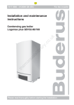
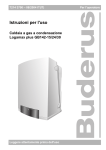
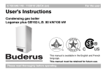
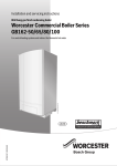
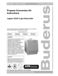
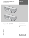
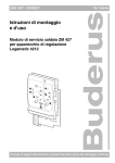
Bulletin Number: TBG-27 | Model: GB142 / GB162 series boilers
Technical service bulletin
High Temperature Limit Validation
Procedure
Subject:
Instructions for High Limit Test
Model GB142/GB162 Series Boilers - CSD-1 field test procedure for high temperature limit validation to meet jurisdictional
requirements.
1. Run boiler at full load using the chimney sweep test mode (
Press and hold chimney sweep button until a decimal point
appears in the lower right corner of the screen.
2. When the supply temperature has reached 176° F (80° C),
close down the isolating valves in the pump manifold assembly
under the boiler (Fig.2, pos.1).
Introduction
The GB142/GB162 boiler is protected against temperature issues
through the UBA (in combination with the supply, return, and high
temperature limit sensors that are part of the boiler). The UBA
monitors a number of situations that are relevant to safe operation of
the boiler including:
•
Absolute sensor temperatures
•
Maximum temperature difference between sensors
•
Maximum temperature increases
•
Minimum temperature decreases
The UBA also monitors the function of the sensors. For example, the
UBA will respond when a sensor has broken down or when there is a
short circuit situation. Generally a 4C (for UBA connection issue),
4Y, CY, 4U, CU, 4P, 4L (for supply, return, or high limit sensors) error
code will display on the BC10 control. Refer to the Service Manual
furnished with the GB142/GB162 boiler for details.
The method of operating the boiler using the boiler control logic
(UBA) and internal temperature sensor for supply, return, and high
limit have been tested and certified by CSA International.
Figure 1
2
3
4
5 6
110
100
90
110
120
130
90
130
150
170
140
1
).
1
GB142
Pump
Group
GB162
Pump
Group
3. After 3 to 5 seconds open them again, but only partially.
4. The boiler will then lockout-shutdown and show a 4A-218 or 4L220 error code because of ‘excessive supply temperature’.
A 2P error code ‘temperature increase of safety sensor too high’
is also possible. Also when the boiler senses too high a temperature difference between the supply and return sensors that is will
provide an error code.
5. When test is complete, press and hold chimney sweep button
( ) until the decimal point disappears in the lower right corner
of the screen. Fully open the isolating valves in the pump manifold
assembly and put the boiler put back into normal operation.
190
12 11 10 9
Figure 2
8
7
Fig. 1 Legend Logamatic BC10 Controller:
1: Main switch
2: DHW temperature knob
7: Under the cover a RC system
controller can be installed.
3: LED "DHW status"
8: LED "Burner Operation"
4: Display
9: Service Tool connector
5: Space heating water
temperature knob
10: "Service" button
6: LED "Heating system status"
12: "Reset" button
11: "Chimney sweep" button
Data subject to change without notice | BTC 435002104 C | 03.2012
Bosch Thermotechnology Corp.
50 Wentworth Ave
Londonderry, NH 03053
Tel: (800) 283-3787
Fax: (603) 965-7568
www.buderus.us
Buderus