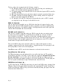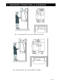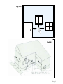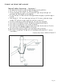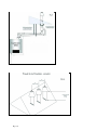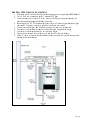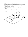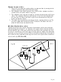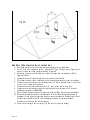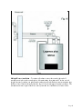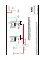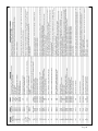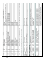
1
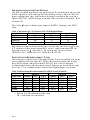
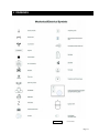
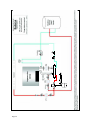
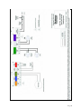
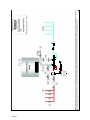
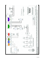
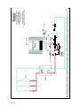
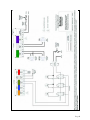
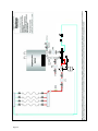
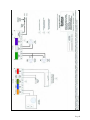
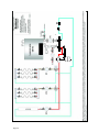
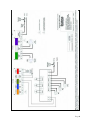
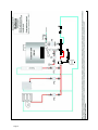
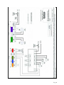
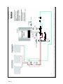
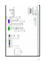
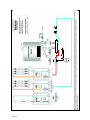
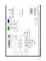
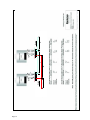
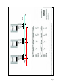
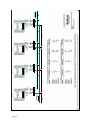
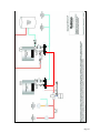
Applications Manual for
Buderus GB142 Wall Hung Heaters
BTC 435001101 A | 05.2009
Table of Contents
1
Introduction
2
Description of Main Componen ts
P re-piped Mani fold and Pump Settin gs
Pump Sizing for Buderus Indirect Tan ks
BC10 Controller
RC10 Room Controller
Space Heating Options
DHW Heati ng Op er at ion
3
5
2
2
4
4
4
4
D esc ription of Ope ra t ion
Dimens ions and Connections
Space Heating
Domestic Hot Water Heating
4
1
5
6
6
Venting Guidelines
7
Horizontal Venting
Vert ical Ven t ing
Condensate Piping
8
9
16
Piping and Wiring Applications
Mechanical / Electrical Symbols
GB142 with DHW zone and indoor reset
GB142 with DHW zone and on/off heating zone
GB142 with DHW zone, Comfort Zone and zone valves
GB142 with DHW zone, Indoor reset, Buderus Pumping Station and
zone valves
GB142 with DHW zone, single temperature of radiant. No Mixing Valve
required
GB142 with DHW zone, motorize mixing valve zone, thermostatic
mixing valves zone and high temperature zone.
17
18
20
22
GB142 with DHW zone, and high temperature on/off zones
30
GB142 with DHW zones, constant circulation w/ Comfort zone control
32
GB142 with DHW zone & the Buderus Quick Fit Modular Piping
systems
Near GB142 Piping with Multiple GB142’s
24
26
28
34
36
Multiple GB142 Units with DWH zone piping diagrams
40
RC10 Error Codes
41
1 DESCRIPTION
2
INTRODUCTION
OF MAIN COMPONENTS
This GB142 Applications Manual is intended to present some of the most common applications
of the wall-hung Buderus GB142 heater for use in hot water space heating applications.
Applications are shown with both piping and corresponding electrical schematics. Auxiliary
equipment depicted does not necessarily represent any one particular manufacturer or specific
model number. There are a wide variety of techniques, practices and piping strategies possible
with hydronic heating systems and it is the responsibility of the installing contractor to determine
the most suitable arrangement for his application.
In an effort to simplify piping and electrical diagrams, only Diagrams 1P and 1E depict the
complete details with respect to piping and wiring of an indirect hot water tank. This part is left
off all subsequent drawings for clarity purposes.
Basic information regarding vent installation, clearances, condensate piping and termination
locations are included as well.
Although this manual covers many common applications for our equipment, system possibilities
are virtually endless. Should you encounter an application that is not covered in this manual or
have any questions regarding any of its content, we encourage you to contact your local sales rep
or us directly at Bosch Thermotechnology Corp.
Page 1
PRE-PIPED MANIFOLD AND PUMP SETTINGS
All GB142 are standard supplied with a pre-piped and wired heater manifold with pump to easily
facilitate required primary/secondary piping for the installing contractor. Shut-offs, relief valve,
pressure and temperature gauge, purge station on the supply leg and built-in flow check and a
Grundfos UPS15-58 3-speed heater pump are included on the return side of the manifold. (Refer
to Diagram 1P).
Table 1 show T values for different speed settings on the UPS15-58 pump for each GB142
model.
Table 1: Max Heater T (ºF) Values for UPS 15-58 Manifold Pump
Heater Model
Speed 1
Speed 2
GB142/24
26
N/A
33
N/A
GB142/30
N/A
32
GB142/45
N/A
43
GB142/60
Speed 3
N/A
N/A
28
32
Integrated heater controls will automatically reduce the heater input once the heater T exceeds
45 ºF regardless of feedback signal from the RC10 control. Complete burner shut-down will
always take place before T exceeds 99 ºF. The maximum flow rates are as follows:
GB142/24 or /30: 11 GPM, model /45: 15 GPM, model /60: 20 GPM.
PUMP SIZING FOR BUDERUS INDIRECT TANKS
All heating zones are piped directly off the supply (left) side of the heater manifold; with heating
returns combined on the return (right side). Piping connections for an indirect tank charging
pump (PS) are included on the heater manifold. Refer to Tables 2 and 3 for tank pump
recommendations for different Buderus indirect tanks. All piping to and from the indirect needs
to be at least 1”. Use a minimum number of elbows and keep piping lengths to a minimum.
Table 2: Indirect Pump Recommendations for GB142/24 and /30 models.
G B1 42 / 24
G B 1 4 2/ 3 0
Tank Model Grundfos Taco**
B&G
Grundfos
Taco**
UP14-42
3*
007
NRF22
UP26-64
0012
S120
UP26-64 0011
PL30
UP26-64
0013
ST150
UP26-64 0014
PL30
UP26-64
0011
ST200
UP26-64 0014
PL30
UP26-64
0011
ST300
NR
0011
PL45
NR
NR
ST400
UP26-64 0014
PL30
UP26-64
0011
SU500
* Refers to Grundfos UP15-42 w/ built-in flow check and speed setting
** Refers to Taco 007 without built-in flow check
NR – combination not recommended
Page 2
B&G
PL30
PL35
PL45
PL30
NR
PL45
Table 3: Indirect Pump Recommendations for GB142/45 and /60 models.
G B1 42 / 45
G B 1 4 2/ 6 0
Tank Model Grundfos Taco** B & G
Grundfos Taco**
B&G
UP26-64 0014
PL36
UP26-64
0011
PL30
S120
UP26-99
NR
PL36
NR
0013
PL36
ST150
UP26-99
NR
PL36
NR
0013
PL36
ST200
UP26-99 0013
PL36
UP26-99
0013
PL36
ST300
UP26-99
NR
NR
UP26-99
NR
NR
ST400
NR
NR
PL36
NR
NR
NR
SU500
NR
0011
PL36
UP26-64 0011
PL30
SU750 ***
PL30
UP26-64
0012
PL30
SU1000 *** UP26-64 0012
* Refers to Grundfos UP15-42 w/ built-in flow check and speed setting
** Refers to Taco 007 without built-in flow check
*** SU750 and SU1000 tanks are non stock. Allow 6 to 8 weeks for delivery.
NR – combination not recommended
Tables 4 and 5 show pump recommendations for 2 and 3 tank systems operating off a single
GB142 heater. Tank pumps are placed in parallel with each tank having its own pump. The
GB142 DHW sensor is placed in one tank; a high limit aquastat is to be installed in other tanks
and wired in series with the pump power to prevent over heating. Domestic water must be drawn
equally from the tanks.
Table 4: Two Tank Systems
GB142/30
Tank B & G Grundfos Taco
ST150 PL50 15-42 009
ST200 PL50 15-42 009
ST300 PL50 15-42 009
ST400 PL50 15-42 009
Table 5: Three Tank Systems
GB142/30
B
&
G
Grundfos Taco
Tank
ST150 NRF22 15-42 008
ST200 NRF22 15-42 008
ST300 NRF22 15-42 008
ST400 NRF22 15-42 008
B&G
PL30
PL30
PL30
PL30
B&G
PL30
PL30
PL30
PL30
GB142/45
Grundfos
26-64
26-64
26-64
26-64
GB142/45
Grundfos
26-64
26-64
26-64
26-64
Taco
B&G
0014
0014
0014
0014
PL30
PL30
PL30
PL30
Taco
B&G
009
009
009
009
PL50
PL30
PL30
PL30
GB142/60
Grundfos
26-64
26-64
26-64
26-64
GB142/60
Grundfos
26-64
26-64
26-64
26-64
Taco
0011
0011
0011
0011
Taco
0014
0014
0014
0014
Electrically the GB142 has 120 V connections for the heater manifold pump PK (4 Amp max),
indirect tank charging pump PS and DHW recirculation pump PZ (Max Amp draw of 5 Amp for
PS and PZ combined).
Page 3
The low voltage side is equipped with the following terminals:
1) RC terminals (orange color) for an indoor room sensor for firing and modulating the
burner. (RC10 control standard supplied with GB142).
2) FA optional outdoor sensor terminals (blue color) connections (requires RC34 controller;
available Fall 2005).
3) WA T-T terminals (light green color) connections for optional conventional thermostat.
4) FW DHW tank sensor terminals (light gray color) for sensing tank water temperature.
(Tank sensor standard supplied with GB142).
5) EV terminals (red color) for connecting of an optional safety such as LWCO, manual
reset high limit or any other type of external limit circuit.
BC10 CONTROLLER
A BC10 control panel is installed in every GB142 which includes a diagnostic display, status
indicator lights, dials for DHW and maximum heater temperature as well as programming and
diagnostic access buttons. A detailed description of all diagnostic and status codes is provided
with the GB142 Installation and Service Manual.
RC10 ROOM CONTROLLER
A RC10 room controller is provided with every GB142 to provide indoor reset and pin point
precision control back to the BC10. The RC10 must be installed in a reference location for
indoor feedback to the GB142. The RC10 will control the modulation and heater water
temperature based on maintaining desired indoor comfort levels. The RC10 is typically placed
in the main living area for optimum comfort and accurate temperature control. Give careful
consideration to the placement of the RC10 sensor.
The use of the RC10 indoor room controller is shown in a number of diagrams to achieve
maximum comfort and efficiency from the product. Suggested timings of the post purge for the
boiler pump (PK) are shown on each wiring diagram.
Note: Never connect a RC10 control and a thermostat or end switch at the same time.
SPACE HEATING OPERATION:
The PK boiler pump operates and the burner fires on a call for heat from the T-T terminal or
from the RC10 controller. Use only T-T connections or RC terminals, but do NOT use both at
the same installation. Once the call for heat is satisfied, the PK pump continues to operate
through an adjustable programmable post-purge cycle before shutting down. The PK pump can
also set to operate continuously for up to 24 hours after the last call for heat.
DHW HEATING OPERATION:
A call for heat from the FW (DHW) sensor brings the control into DHW priority, shutting off the
PK pump, firing the boiler to maximum temperature and operating the PS pump. Internal logic
includes an anticipative DHW heating cycle with automatically adjusting post purge feature and
reduces burner modulation rate.
Page 4
3 DIMENSIONS, CONNECTIONS and
ANDCLEARANCES
CLEARANCES
Fig. 1: Dimensions and Connections for GB142/24 and /30.
Fig. 2: Dimensions and Connections for GB142/45 and /60.
Page 5
4 VENTING GUIDELINES
VENTING GUIDELINES
The GB142 is suitable for side-wall as well as vertical venting using field supplied 3” PVC or
CPVC pipe in compliance with ANSI, ASTM D1785 (schedule 40 PVC), F441, D2665 (PVCDWV), or ABS-DWV Schedule 40. Cement and primer must comply with ASTM D2564. For
Canada, use CSA or ULC certified PVC or CPVC pipe, fittings and cement. Foam core PVC
pipe can not be used.
Note: Installation must comply with local requirements/codes, National Fuel Gas Code, ANSI
Z223.1 (USA installations) CSA B149.1 or B149.2 (Canadian installations). In Canada, venting
must comply with ULC-S636.
Note: Installing contractor must install condensate tee (supplied by Buderus) immediately after
the first 90 degree flue elbow. Condensate must be drained into a condensate pump or
appropriate drain.
The GB142 is approved for both Direct Vent (sealed-combustion - see FIG. 3A for termination
location) as well as Direct Exhaust (non sealed-combustion - see FIG. 3B for termination
location) operation in both a horizontal and vertical vent arrangement. For room air applications,
follow National Fuel Gas Code to ensure ample combustion air. All PVC venting material is
approved for 0” clearance to combustibles for venting of the GB142 boiler.
Table 6: Maximum Equivalent Vent Lengths
Model
Max Eq. Intake Length (ft)
GB142/24, /30, /44
GB142/60
100
60
Max Eq. Exhaust Length (ft)
Table 7: Friction Loss Equivalent for Fittings
Fittings or Piping
Equivalent Length (ft)
4 5 º Elb ow
9 0º Elb ow
Optional Concentric Vent Kit
Page 6
3
5
3
100
60
Fig. 3A
12"
minimum
12"
minimum
12"
minimum
Fig 3B
Page 7
DIRECT VENT/SEALED COMBUSTION & DIRECT VENT/NON-SEALED
COMBUSTION TERMINATION GUIDELINES
WARNING: Follow these instructions when determining vent termination location to avoid
possibility of severe personal injury, death, substantial property damage or cross contamination
of combustion air. Gas vent extending through an exterior wall shall not terminate adjacent to the
wall or below building extensions such as eaves, parapets, balconies or decks. Failure to comply
could result in severe personal injury, death or substantial property damage. Locate the
concentric vent/air termination using the following guidelines.
The total length of piping for vent or combustion air should not exceed the limits in Table
6 for maximum output.
One must consider the immediate environment when locating the vent/air termination.
Gases will form a white plume in winter. Plume could obstruct window view.
Prevailing winds could freeze condensate and cause water/ice buildup on building,
plants or roof. Do not terminate vent in window well, stairwell, alcove, courtyard, or
other recessed areas.
Maintain Minimum Clearances below to prevent potential problems;
1. Vent must terminate at least 12 inches above grade, anticipated snow line or roof
surface (Canada 18” minimum).
2. Vent termination must be at least 7 feet above a public walkway.
3. Vent must be 3 feet above any forced air intake within 10 feet.
4. Vent must terminate at least 3 feet horizontally, from electric meters, gas meters,
regulators, relief valves, and other equipment, and in no case above or below, unless a
3 feet horizontal distance is maintained
5. Do not extend exposed vent pipe outside the building beyond recommended distance.
Condensate could freeze and block vent pipe.
6. Vent should terminate at least 3 feet away from adjacent walls, inside corners and
below roof overhang.
7. It is not recommended to terminate vent above any door or window, condensate can
freeze causing ice formations.
8. Do not use chimney as a raceway if another appliance or fireplace is vented into or
through chimney.
9. The exhaust vent must be pitched up toward the termination a minimum of ¼” in. per
foot. Condensate must flow back to the Boiler freely, without accumulating in the
vent.
10. Multiple boiler vent terminations; See Venting application.
Page 8
EXHAUST AND INTAKE AIR PLACEMENT
THROUGH THE ROOF PENETRATION — CONCENTRIC*:
1. Determine best location for vent/air termination using previous guidelines.
2. Cut a 5” hole to accommodate the 4½” diameter PVC pipe.
3. Cement termination concentric Y to 4½” diameter PVC pipe, then pass through roof
penetration and field supplied roof boot/flashing.
4. Secure assembly to roof structure with field supplied metal strapping or equivalent support
material.
5. Insert smaller 2½” PVC vent exhaust pipe into larger 4½” diameter combustion air pipe
ensuring PVC exhaust vent pipe is properly cement into concentric Y.
6. Cement vent exhaust pipe and air inlet pipe onto concentric vent termination.
7. Concentric vent termination cannot be extended beyond manufactured length.
8. Concentric vent termination may be cut to desired length.
9. Concentric vent shall terminate at least 12 inches above snow line but not more 24 inches
above roof surface. (see FIG.4 and FIG. 5 for details)
10. Operate heater through one complete cycle and check for flue gas leakage.
11. Refer to fig. 6 for multiple “Through the roof” installations and maintain a 12” center-tocenter distance.
* Buderus Part Number: BRYKGAVT0602CVT
Page 9
Page 10
SIDE-WALL PENETRATION (CONCENTRIC)
1. Determine best location for vent/air termination using previous guidelines (FIG. 3A & 7).
2. Cut a 5” hole to accommodate the 4½” diameter PVC pipe.
3. Cement termination concentric Y to 4½” diameter PVC pipe, then pass through wall
penetration and field supplied flashing if required.
4. Insert smaller 2½” PVC vent exhaust pipe into larger 4½” diameter combustion air pipe
ensuring PVC exhaust vent pipe is properly cement into concentric Y.
5. Cement vent exhaust pipe and air inlet pipe onto concentric vent termination.
6. Concentric vent termination cannot be extended beyond manufactured length.
7. Concentric vent termination may be cut to desired length.
8. Operate heater through one complete cycle and check for flue gas leakage.
9. Allow 8” center to center horizontal distance between concentric vent terminations with
multiple heater installations.
Page 11
THROUGH THE ROOF PENETRATION (NON-CONCENTRIC)
1. Determine best location for vent/air termination using previous guidelines.
2. Air pipe penetration – Cut a hole for the air pipe. Size the air pipe hole as close as desired
to the air pipe outside diameter.
3. Vent pipe penetration – Cut a hole for the vent pipe. Size the vent pipe hole as close as
desired to the vent pipe outside diameter.
4. Space the air and vent holes to provide the minimum spacing (see FIG. 8).
5. Follow all local codes for isolation of vent pipe when passing through floors, ceilings and
roofs.
6. Install a field supplied roof penetration boot/flashing.
Fig. 8
24"
minimum
Minimum 12"
Maximum 24"
Page 12
Minumum of
12" above roof
line/snow line
TERMINATION AND FITTING
1. Prepare the vent termination coupling and the air termination elbow by inserting the bird
screens provided with boiler into the three inch fittings.
2. The combustion air inlet shall terminate at least 12 inches above maximum snow line or
24 inches above roof surface which ever is greater.
3. The combustion air inlet pipe must terminate in a downward position using two 90 degree
elbows. The combustion air inlet pipe shall terminate at least two feet horizontally from
the center line of the exhaust vent, this is to prevent cross contamination of flue gases
into the combustion air stream.
4. The exhaust vent must terminate vertically upward with a coupling and bird screen. The
top of the coupling shall termination at least 12 inches above the bottom of the downturned 90° elbow, but no more than 24 inches.
MULTIPLE HEATER INSTALLATION
Terminate all exhaust vents at the same height and all combustion air inlets at the same height,
while maintaining the minimum 12” to a maximum of 24” height clearance from the exhaust to
the down turned 90 degree elbow and combustion air inlet. Exhaust vent termination edge shall
be at least 12” from the edge of the air inlet pipe of an adjacent heater. Exhaust vent terminations
may be place next to each other as practical, like wise air intake terminations may also be placed
next to each other. The combustion air inlet is part of the direct vent system and not classified as
a forced air inlet (see FIG. 9A and 9B).
Fig. 9A
Minimum 12"
Maximum 24"
Minimum 24" from
center to center
12"
Minimum
Page 13
SIDE-WALL PENETRATION (NON-CONCENTRIC)
1. Determine best location for vent/air termination using previous guidelines.
2. Cut a 4” hole to accommodate the 3½” diameter PVC pipe. Through the wall penetration
may be sealed with a field provided flashing if required.
3. Insert bird screens provided with heater into both exhaust and combustion air (field
supplied) elbows.
4. Combustion air inlet elbow should always be positioned downward.
5. The exhaust outlet or elbow shall always be positioned pointing away from the building.
6. Combustion air inlet elbow must terminate at least 12” below exhaust elbow or outlet, but
not exceed 15” maximum separation.
7. Combustion air inlet must maintain at least 12” above grade and/or snow line.
8. Combustion air inlet may be extended vertically upward a maximum of 24” from the
building penetration (see FIG. 10).
9. Do not extend exposed exhaust vent pipe outside the building beyond recommendations.
10. Horizontal termination shall not extend beyond 18 inches from the building (based on
minimum 12 inch required separation between intake and exhaust). Exhaust vent vertical
rise shall not extend beyond 39” from building penetration to termination elbow.
Condensate could freeze and block vent pipe.
11. Operate heater through one complete cycle and check for flue gas leakage.
Page 14
Multiple Heater installation – Terminate all exhaust vents at the same height and all
combustion air inlets at the same height, while maintaining the minimum 12 inches vertical
height clearance from between exhaust and combustion air inlet. Exhaust vent termination edge
shall be at least 12 inches laterally from the edge of the air inlet pipe of an adjacent heater. The
combustion air inlet is part of the direct vent system and not classified as a forced air inlet.
Page 15
CONDENSATE PIPING
Figure 7 shows a typical sealed combustion installation.
The furnished 3” x ¾” socket female vent condensate drain must be installed as close as
possible to the exhaust connection with the ¾” branch pointing down to drain condensate.
Install furnished 1-1/2” x ¾” coupling under GB142 condensate drain, install a ¾” PVC
tee and bring in upper vent drain with a trap into this tee.
Pour 1 qt. of water in exhaust pipe and make sure to fill the external trap and internal trap
of the GB142.
In case of vertical venting, install a short horizontal run to install the vent condensate
drain.
Page 16
55 DRAWINGS
DRAWINGS
Low Loss Header
Version 1.2 04/05
Page 17
Page 18
Version 1.2 04/05
Page 19
Page 20
Version 1.2 04/05
Page 21
Page 22
Version 1.2 04/05
Page 23
Page 24
Version 1.2 04/05
Page 25
Page 26
Version 1.2 04/05
Page 27
Page 28
Version 1.2 04/05
Page 29
Page 30
Version 1.2 04/05
Page 31
Page 32
Version 1.2 04/05
Page 33
Page 34
Version 1.2 04/05
Page 35
Page 36
Version 1.2 04/05
"A"
Supply
"E"
"B"
"B"
"E"
"A"
Return
Page 37
"A"
Supply
"E"
"B"
"C"
"E"
"C"
"B"
"E"
"A"
Return
Page 38
Version 1.2 04/05
"A"
Supply
"E"
"B"
"D"
"E"
"C"
"C"
"E"
"D"
"B"
"E"
"A"
Return
Version 1.2 04/05
Page 39
Page 40
Version 1.2 04/05
Page 41
Page 42
Bosch Thermotechnology Corp.
50 Wentworth Avenue
Londonderry, NH 03053
Tel: 1-800-BUDERUS
Fax: 1-603-584-1681
www.buderus.net
Bosch Thermotechnology Corp., reserves the right to make changes without notice
due to continuing engineering and technological advances