1
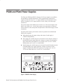
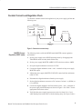
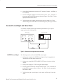
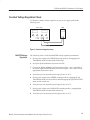
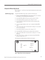
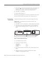
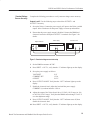
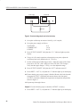
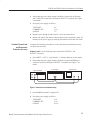
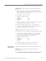
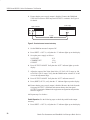
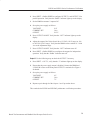
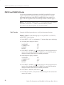
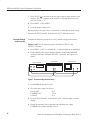
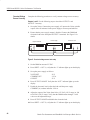
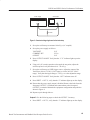
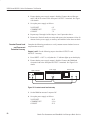
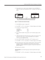
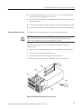
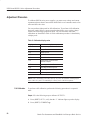
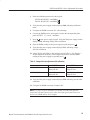
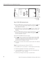
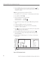
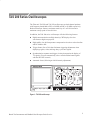
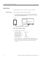
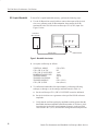
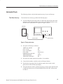
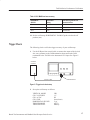
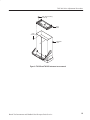
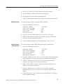
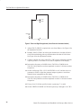
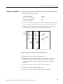
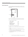
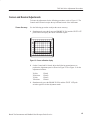
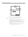
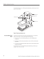
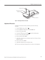
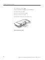
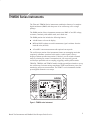
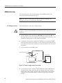
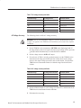
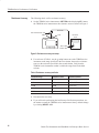
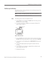
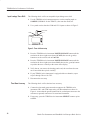
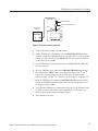
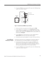
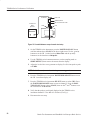
PS2520 and PS2521 Series Performance Verification
8. Press OUTPUT ON/OFF. Verify that the “OUT” indicator turns off; then
disable the electronic load.
9. Press SHIFT → PARA/INDEP to reconfigure the outputs for independent
operation. Verify that the “PARA” indicator turns off.
Output 3. Use the following steps to check the OUTPUT 3 accuracy.
1. Press SHIFT → OUT 3; verify that the “3” indicator lights up on the display.
2. Ensure that the power supply output is disabled. Connect the DMM and
electronic load to the front panel OUTPUT 3 terminals. Maintain the
equipment configuration and polarities shown in Figure 3.
3. Set up the power supply as follows:
VOLTS SET
CURRENT SET
OVP SET
6V
5.1 A
7V
4. Press OUTPUT ON/OFF. Verify that the “OUT” indicator lights up on the
display.
5. Enable the electronic load. Adjust the load until the power supply
CURRENT (A) readout indicates 5.000 A.
6. Adjust the output of the Variac from 108 to 132 VAC (120 V range) or 198
to 242 VAC (220 V range). Verify that the DMM readout changes ≤0.003
volts over the adjustment range.
7. Press OUTPUT ON/OFF; then disable the electronic load.
8. Disconnect the DMM and electronic load from the instrument.
Constant Voltage
Ripple and Noise
Accuracy
Complete the following procedures to verify constant voltage ripple and noise
accuracy.
Outputs 1 and 2. Use the following steps to check the OUTPUT 1 and
OUTPUT 2 accuracy.
1. Press SHIFT → OUT 1; verify that the “1” indicator lights up on the display.
2. Ensure that the power supply output is disabled. Connect the oscilloscope
and 27 W 75 W resistor to the front panel OUTPUT 1 terminals. See
Figure 4 for details.
48
Bench Test Instruments and Handheld Oscilloscopes Basic Service