1
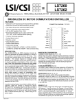
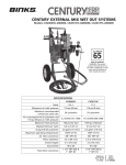
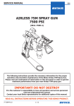
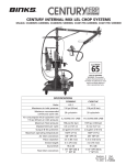
Binks Model 7N Spray Gun Binks Model 7N Gun is a rugged, light weight, hand held Spray Gun, for applying gel-coats and polyester resins. Catalyst is introduced to the material stream through the atomizing air as the resin flows from the Material Nozzle. Flow rate of the Gun varies up to 2 GPM depending on nozzle selection. The actual fluid output is controlled by nozzle orifice size and fluid pressure. Nozzle Types Internal Mix—Low to high material volume, low air consumption. External Mix—Low material volume, fine atomization. Spray patterns are determined by the nozzle selection and vary somewhat depending on size, angle, nozzle orifice and output. External mix nozzle pattern cannot be changed because this gun does not have a side port control. However, its spray fan pattern can be rotated through 360° by loosening the Retaining Ring, and rotating the Nozzle Body, Item 1. Faulty spray patterns can be caused by: 1. Foreign material in Air and/or Fluid Passages. 2. Viscosity too high for spraying. Air supply or pressure inadequate. 3. Worn or damaged Nozzle surfaces. 4. Gellation in Gun Head Air Passages. 5. Gun Head Check-Valve, Items 6, 7, 8 frozen. Gun Cleaning Submerging the Gun in solvent will not harm the Gun; however, it can adversely affect the Nozzle “O” Ring, Item 2. Submerging is poor practice because of the solvent residue that may cling to interior air passages. Clean solvent MUST be used if the Gun is to be submerged. The best practice is to remove the Air Nozzle and to flush solvent through the fluid passages. All Nozzles may be placed in solvent for washing. The Nozzle Orifice and angle passage ways are critical. Always wash and rinse with a clean solvent to prevent residue accumulation in the minute holes. NEVER use metal instruments for cleaning. Resin Packing Packing take-up is accomplished by tightening Packing Nut, Item 38, with a wrench. Packing replacement is simple; proceed as follows: 1. Remove Fluid Control Screw, Item 17. 2. Remove Needle Assembly, Item 16. NOTE Needle Lock Nuts, on the 59SS Needle, must be first removed from the rear of the Needle, and the Needle then extracted from the head end of the Gun. The 68SS Needle can be pulled out from the rear of the Gun. 3. Remove Packing Nut, Item 38, and old Packing, Item 37, from Cavity. 4. Insert new Packing in Cavity. 5. Reassemble items removed in (1), (2) and (3) above. 6. Set Packing, Item 37, by tightening Packing Nut, Item 38, until Needle movement, Item 16, is resisted, then loosen approximately 1/2-3/4 turn. Air Leaks: Through Gun Head 1. Leaky Air Valve, Item 28. Inspect, clean, or replace. 2. Air Valve Body, Item 30, not seated. Tighten. 3. Air Valve Body Gasket, Item 26, missing or damaged. Replace. 4. Damaged Seat surface in Gun Body, Item 22. Replace. At Air Catalyst Valve, Item 28 1. Around Air Valve Stem, Item 29. Tighten or replace Packing, Item 31. 2. Damaged Air Valve Stem. Inspect and replace if necessary. 3. Damaged Seat surfaces. Attempt repair with PTFE tape. Replace if necessary. Check-Valve Cleaning A Check-Valve in the Head of the Gun prevents resin from backing up into Air/Catalyst Passage. However, resin buildup periodically may cause the Ball to freeze in the Head. To free Ball: 1. Remove Plug, Item 11, Fluid Needle Assembly, Item 16, and Packing Nut, Item 38. 2. Insert Wrench, Part No. 73-165, and turn counter-clockwise to remove Head, Item 5, and Check-Valve Components, Items 6, 7, and 8. 3. Clean as required and reassemble. Exterior surfaces of Gun should be kept clean by wiping with a solvent-wet cloth. Replaces Part Sheet 77-2709R-10 Part Sheet 77-2709R-11 In this part sheet, the words WARNING, CAUTION and NOTE are used to emphasize important safety information as follows: ! WARNING Hazards or unsafe practices which could result in severe personal injury, death or substantial property damage. ! Caution Hazards or unsafe practices which could result in minor personal injury, product or property damage. ! NOTE Important installation, operation or maintenance information. Warning Read the following warnings before using this equipment. Read the Manual Before operating finishing equipment, read and understand all safety, operation and maintenance information provided in the operation manual. Plural Component Materials Hazard Because of the vast number of chemicals that could be used and their varying chemical reactions, the buyer and user of this equipment must determine all facts relating to the materials used, including any of the potential hazards involved. Wear Safety Glasses Failure to wear safety glasses with side shields could result in serious eye injury or blindness. Noise Hazard You may be injured by loud noise. Hearing protection may be required when using this equipment. De-energize, DEPRESSURIZE, Disconnect and Lock Out All Power Sources During Maintenance Failure to De-energize, disconnect and lock out all power supplies before performing equipment maintenance could cause serious injury or death. Fire and Explosion Hazard Improper equipment grounding, poor ventilation, open flame or sparks can cause hazardous conditions and result in fire or explosion and serious injury. Operator Training All personnel must be trained before operating finishing equipment. Pinch Point Hazard Moving parts can crush and cut. Pinch points are basically any areas where there are moving parts. Equipment Misuse Hazard Equipment misuse can cause the equipment to rupture, malfunction, or start unexpectedly and result in serious injury. Know Where and How to Shut Off the Equipment in Case of an Emergency Keep Equipment Guards in Place Do not operate the equipment if the safety devices have been removed. Pressure Relief Procedure Always follow the pressure relief procedure in the equipment instruction manual. High Pressure Consideration High pressure can cause serious injury. Relieve all pressure before servicing. Spray from the spray gun, hose leaks, or ruptured components can inject fluid into your body and cause extremely serious injury. CA PROP 65 PROP 65 WARNING WARNING: This product contains chemicals known to the State of California to cause cancer and birth defects or other reproductive harm. IT IS THE RESPONSIBILITY OF THE EMPLOYER TO PROVIDE THIS INFORMATION TO THE OPERATOR OF THE EQUIPMENT. FOR FURTHER SAFETY INFORMATION REGARDING BINKS AND DEVILBISS EQUIPMENT, SEE THE GENERAL EQUIPMENT SAFETY BOOKLET (77-5300). 2 ! Warning when using Binks equipment with Methyl Ethyl Ketone Peroxide in Plasticizer OBSERVE the following precautions corrosive to the eyes – may cause blindness. may be fatal if swallowed. strong irritant. contamination or heat may lead to fire or explosive decomposition. combustible. Do not handle or use until safety precautions concerning Methyl Ethyl Ketone Peroxides in the Manufacturer’s literature have been read and understood. Contact with foreign materials, especially strong mineral acids, metals (including certain equipment and containers) or metal salts, or exposure to heat above 135° F (57° C) may lead to violent decomposition, releasing flammable vapors which may self-ignite. Do not get into eyes or on skin or clothing. Wear eye and skin protection when handling. Avoid breathing mist. Use with adequate ventilation. Store only it in the original closed container. Wash hands thoroughly after handling. Protect from direct sunlight, heat, sparks and other sources of ignition. Prevent contamination with foreign materials. Do not add to hot materials. FIRST AID EYES Wash immediately (seconds count) with water and continue washing for at least 15 minutes. Obtain medical attention. SKIN Wash with soap and water. Remove contaminated clothes and shoes and again wash thoroughly with soap and water. SWALLOWING Administer large quantities of milk or water. Obtain immediate medical attention for lavage. To maintain the chemical activity store below 100° F (38° C). In case of fire, use water spray, foam or dry chemical. In case of spill or leak, absorb or blend with inert, non-combustible material. Put in suitable container. Dispose of immediately in accordance with federal, state and local regulations. Do not reuse container as some of the original hazardous contents may still be present. Follow the above precautions in handling. 3 Model 7N PARTS LIST (When ordering, please specify Part No.) ITEMPART ITEMPART NO. NO.DESCRIPTIONQTY. NO. NO.DESCRIPTIONQTY. 1 2 3 4 5 6 7 8 9 10 11 12 13 16 17 18 19 20 21 22 23 24 ★✝✝ AIR NOZZLE. . . . . . . . . . . . . . . . . . . 1 20-5052 ● ■ “O” RING. . . . . . . . . . . . . . . . . . . . . 1 ★ FLUID NOZZLE. . . . . . . . . . . . . . . . . 1 20-3600 ●GASKET . . . . . . . . . . . . . . . . . . . . . . 1 54-1293 GUN HEAD. . . . . . . . . . . . . . . . . . . . 1 101-5254 SPRING. . . . . . . . . . . . . . . . . . . . . . . 1 20-1544 BALL, 5/16" dia. . . . . . . . . . . . . . . . 1 102-513 SCREW. . . . . . . . . . . . . . . . . . . . . . . 1 54-759 TRIGGER SCREW . . . . . . . . . . . . . . . 1 54-760 TRIGGER STUD. . . . . . . . . . . . . . . . . 1 102-916 BODY PLUG. . . . . . . . . . . . . . . . . . . 1 54-723 ● “O” RING. . . . . . . . . . . . . . . . . . . . . 1 102-275 FLUID CONTROL HOUSING. . . . . . . 1 ★★ FLUID NEEDLE VALVE ASSemblY. . 1 54-724 FLUID CONTROL ASSemblY. . . . . . 1 54-725 FLUID CONTROL SCREW. . . . . . . . . 1 54-728 ● FLUID CONTROL SPRING. . . . . . . . . 1 54-727 FLUID CONTROL RING. . . . . . . . . . . 1 54-726 FLUID CONTROL . . . . . . . . . . . . . . . 1 102-264 GUN BODY. . . . . . . . . . . . . . . . . . . .1 54-1838 AIR CONNECTION. . . . . . . . . . . . . . 1 54-2416 PLUG ASSEMBLY. . . . . . . . . . . . . . . 1 25 26 27 28 29 30 31 32 33 34 35 36 37 38 39 40 41 54-753 54-2418 ● 54-1964 ● 102-2615 54-744 ● 54-751 54-2419 ● 54-2417 54-1241 54-718 54-721 54-722 ● 2-28 ● 54-1407 54-2524 54-2527 54-3009 73-165 OMX-88 TRIGGER ASSEMBLY . . . . . . . . . . . . 1 AIR VALVE GASKET. . . . . . . . . . . . . 1 AIR VALVE SPRING . . . . . . . . . . . . . 1 AIR VALVE ASSembly. . . . . . . . . . . 1 AIR VALVE STEM. . . . . . . . . . . . . . . 1 AIR VALVE BODY. . . . . . . . . . . . . . . 1 AIR VALVE PACKING. . . . . . . . . . . . 1 AIR VALVE PACKING NUT. . . . . . . . 1 SLEEVE ASSEMBLY. . . . . . . . . . . . . . 1 SLEEVE. . . . . . . . . . . . . . . . . . . . . . . 1 WIPER CUP RETAINER. . . . . . . . . . . 1 WIPER CUP. . . . . . . . . . . . . . . . . . . . 2 NEEDLE PACKING . . . . . . . . . . . . . . 1 NEEDLE PACKING NUT. . . . . . . . . . 1 RING. . . . . . . . . . . . . . . . . . . . . . . . . 1 SEAL. . . . . . . . . . . . . . . . . . . . . . . . . 1 BASE. . . . . . . . . . . . . . . . . . . . . . . . . 1 WRENCH (Not Shown) . . . . . . . . . . 1 CLEANING BRUSH (Not Shown). . . 1 NOTE: See Page 6 for Model 102-2138 Flush Valve Assembly. ★ When ordering, please specify Part Number stamped on Nozzle. ★★When ordering, please specify Gun model and Part Number stamped on Needle Stem. ● Parts also available in Spare Parts Kit 106-1061. Kit not furnished, please order separately. ✝✝ Use only “Blue Ring” Nozzles and Bases which have special Seal Groove. ■ Included with Item 1 and Item 41. Nozzle Chart for Binks Model 7N Air/Catalyst Spray Gun FLUID TYPE (VISCOSITY) Nozzles BLUE RING FLUID x AIR NOZZLE Medium to Heavy Cream-Like (Over 75 CPS) (Over 28 Sec. Ford 4) 68SS x A68PB 68SS x 302 FLUID Nozzle Orifice size (In.) Air Nozzle Type .110 .110 PE PI MAX. Air requirements (CFM) PATTERN At Indicated P.S.I. AT 8" (Inches) 30 50 70 12 8 9.5 14.1 6.5 19.1 needle No. 39 39 NOTE: All External Mix Nozzles must be the “Blue-Ring” series. This series incorporates an O-Ring Seal between the shoulder of the Fluid Nozzle and the taper of the Air Nozzle (or Air Nozzle Base). Other fluid nozzles and air nozzles available. Contact Binks technical support for more information. 4 5 2 1 3 2 4 32 Internal Mix USE CARE IN REMOVING. PREVENT NICKS AND DENTS IN SEAT SURFACE: IMPROPER WRENCH SIZE OR USAGE MAY DAMAGE SEAT AREAS NEAR WRENCH FLATS. EXternal Mix 1 39 40 41 5 NOTE 31 33 6 34 28 30 7 29 8 35 37 9 27 36 38 26 10 To prevent damage to “O” Ring, Item 2, during assembly of either Internal or External Mix Nozzles, insert “O” RIng into Base, Item 41, or Air Nozzle, Item 1, making sure “O” Ring is well-centered and bottomed in its groove. Hold Gun vertically, Gun Head, Item 5 down, and screw Base or Nozzle into Gun Head Threads. 11 25 12 24 23 21 13 20 17 1/4 NPT accessory: 102-3430 ACI VALVE REF. PART SHEET 77-2130 19 18 16 Binks 7N Gun Accessories Binks MODEL 102-2138 Flush Valve Assembly for Model 7N Gun INSTALLATION INSTRUCTIONS 1. Remove Air Connection, Item 23, (see Page 4 Parts List) from Gun Handle. 2. Remove Plug Assembly, Item 24, (see Page 4 Parts List) from Gun Handle. 3. Insert Stem, Item 7, (with “O” Ring) of Valve Assembly into Hole from which Plug Assembly was removed. NOTE: Valve Assembly does not have to be screwed in tightly; the “O” Ring at the top of the Stem provides a complete air seal. Apply a small amount of petroleum jelly to “O” Ring before inserting Stem into Gun Handle. 4. Rotate Valve Assembly so that the flat face of its Body, Item 11, (containing the groove) allows clearance for inserting Air Connection, Item 1, into Hole in base of Gun from which Air Connection (see Step 1 above) was removed. 5. Insert Air Connection, Item 1, and screw up tightly. 6. Hook up Solvent Flush Hose to Valve Assembly at D.M. Nipple, Item 17. 7. Hook up Air Hose to Air Connection, Item 1. 2 3 4 5 1 6 7 8 9 10 PARTS LIST 11 (When ordering, please specify Part No.) ITEM PART NO. NO.DESCRIPTIONQTY. ITEM PART NO. NO.DESCRIPTIONQTY. 1 54-2138 2 20-3847 354-2407 4 20-4544 554-2139 6 20-2183 754-2408 8102-2136 9102-2142 10102-2135 11102-2132 12102-2133 1354-2419 1454-2417 15 20-3750 16102-2137 17 72-792 6 AIR CONNECTION . . . . . “O” RING . . . . . . . . . . . . CAP . . . . . . . . . . . . . . . . “E” RING . . . . . . . . . . . . SPRING . . . . . . . . . . . . . BALL, 3/16 in. dia . . . . . STEM . . . . . . . . . . . . . . . CAP . . . . . . . . . . . . . . . . 1 1 1 1 1 1 1 1 SPRING . . . . . . . . . . . . . . STEM ASSemblY . . . . . . BODY . . . . . . . . . . . . . . GLAND . . . . . . . . . . . . . . PACKING . . . . . . . . . . . . CAP . . . . . . . . . . . . . . . . SET SCREW, 6-32 . . . . . . BUTTON . . . . . . . . . . . . . D.M. NIPPLE, 1/8 NPT x 1/4 NPS . . . . . 1 1 1 1 1 1 1 1 1 12 13 17 16 14 15 NOTES 7 WARRANTY This product is covered by Binks’ 1 Year Limited Warranty. Binks Sales and Service: www.binks.com U.S.A./Canada Customer Service 195 Internationale Blvd. Glendale Heights, IL 60139 630-237-5000 Toll Free Customer Service and Technical Support 800-992-4657 77-2709R-11 Revisions: Trademark updates. Toll Free Fax 888-246-5732 10/12 ©2012 Binks All rights reserved. Printed in U.S.A.