1
Visit us at www.swisherinc.com
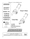
OWNER’S
MANUAL
MODEL NO.
Trim-N-Mow
STARTING SERIAL # L212-291001
ST67522BS
ST67522BS-TSC
DST67522BS
Trim-Max
IMPORTANT
Read and follow all
Safety Precautions
and Instructions
before operating this
equipment.
Assembly
Operation
Service and Adjustment
Repair Parts
1602 CORPORATE DRIVE, WARRENSBURG MISSOURI 64093
PHONE 660-747-8183 FAX 660-747-8650
10698 REV 12-291
Made In The
USA
LIMITED WARRANTY
The manufacturer’s warranty to the original consumer purchaser is: This product is free from defects in
materials and workmanship for a period of two (2) years from the date of purchase by the original consumer
purchaser. We will repair or replace, at our discretion, parts found to be defective due to materials or
workmanship. This warranty is subject to the following limitations and exclusions:
1) Engine Warranty
All engines utilized on our products have a separate warranty extended
to them by the individual engine manufacturer. Any engine service
difficulty is the responsibility of the engine manufacturer and in no way
is Swisher or its agents responsible for the engine warranty. The Briggs
& Stratton Engine Service Hot Line is 1-800-233-3723.
2) Commercial Use
This product is not intended for commercial use and carries no
commercial warranty.
3) Limitation
This warranty applies only to products which have been properly
assembled, adjusted, and operated in accordance with the instructions
contained within this manual. This warranty does not apply to any
product of Swisher that has been subject to alteration, misuse, abuse,
improper assembly or installation, shipping damage, or to normal wear
of the product.
4) Exclusions
Excluded from this warranty are normal wear, normal adjustments, and
normal maintenance.
In the event you have a claim under this warranty, you must return the product to an authorized service
dealer. All transportation charges, damage, or loss incurred during transportation of parts submitted for
replacement or repair under this warranty shall be borne by the purchaser. Should you have any questions
concerning this warranty, please contact us toll-free at 1-800-222-8183. The model number, serial number,
date of purchase, and the name of the authorized Swisher dealer from whom you purchased the mower will
be needed before any warranty claim can be processed.
THIS WARRANTY DOES NOT APPLY TO ANY INCIDENTAL OR CONSEQUENTIAL DAMAGES
AND ANY IMPLIED WARRANTIES ARE LIMITED TO THE SAME TIME PERIODS STATED
HEREIN FOR ALL EXPRESSED WARRANTIES. Some states do not allow the limitation of
consequential damages or limitations on how long an implied warranty may last, so the above limitations or
exclusions may not apply to you. This warranty gives you specific legal rights and you may have other
rights, which vary from state-to-state. This is a limited warranty as defined by the Magnuson-Moss Act of
1975.
2
Safety Instructions
This Safety Alert Symbol indicates important messages in this
manual. When you see this symbol, carefully read the message that
follows and be alert to the possibility of personal injury.
•
•
•
•
•
•
•
•
•
•
•
•
•
•
•
•
•
•
•
•
•
•
Read, understand and follow all instructions in the manual and on the trimmer
before starting.
Read this manual carefully. Become familiar with the controls and how to
operate the unit properly.
Only allow responsible adults, who are familiar with the instructions, to
operate the unit.
Clear the area of objects such as rocks, toys, etc. that could be thrown by the
unit.
Be sure the area is clear of other people before trimming. Stop the unit if
anyone enters the area.
Be aware of the direction of the trimmer discharge and do not direct it at
anyone. Do not direct trimmer discharge at breakable objects, such as
windows, etc.
Do not operate trimmer without all guards and shields in place.
Never leave the machine running unattended.
Trim only in daylight or good artificial light.
Do not operate the trimmer while under the influence of alcohol or drugs.
Watch for traffic when operating near roadways.
Use the trimmer as the manufacturer intended and as described in the
manual.
Do not operate trimmer if it has been dropped or damaged in any manner.
Always have the damage repaired before operating.
Always wear safety glasses or eye shields when using the trimmer.
Dress properly. Do not operate the trimmer when barefoot or wearing open
sandals. Wear only solid shoes for good traction when trimming. Wear long
sleeved shirts or jackets, also long pants. Do not trim in shorts.
Keep your eyes and mind on your trimmer and the area being trimmed.
Do not let other interests distract you.
Do not put hands and feet near or under rotating parts.
Before cleaning, inspecting or repairing your trimmer, stop the engine and
disconnect the spark plug wire and keep it away from the spark plug to
prevent accidental starting.
Do not operate the trimmer if it vibrates abnormally. Excessive vibration is a
sign of damage. Stop the engine and safely check for damage and repair as
required.
Do not operate the trimmer in wet grass, where good footing may not be
possible. Walk, never run.
Stop the trimmer when crossing gravel drives, etc.
3
Slope Operation
Slopes are a major factor related to loss of control and slip accidents,
which can result in severe injury. All slopes require extra caution. If you
feel uneasy on it do not trim it.
•
•
•
•
•
•
DO: Trim across the face of a slope and not up and down.
DO: Remove objects such as rocks, tree limbs, etc.
DO: Watch for holes, ruts or bumps. Tall grass can hide obstacles.
DO NOT: Mow near drop-offs, ditches or embankments. The operator could
lose footing or balance.
DO NOT: Trim excessively steep slopes.
DO NOT: Trim on wet grass. Reduced footing could cause slipping.
Children
K eep children out of the area and under the watchful care of another
responsible adult.
B e alert and turn the m achine off if children enter the area.
B efore and when backing, look behind and down for sm all children.
N ever allow children to operate this m achine.
U se extra care when approaching blind corners, shrubs, trees or other objects
that m ay obstruct vision.
•
•
•
•
•
Service
•
•
•
•
•
•
•
•
•
•
•
•
Use extra care handling gasoline and other fuels. They are flammable and
vapors are explosive.
Use only an approved container.
Never remove gas cap or add fuel with the engine running.
Allow engine to cool before refueling. Do not smoke while refueling.
Never refuel the machine indoors.
Never store the machine or fuel container where there is an open flame, such
as a water heater.
Never run a machine inside a closed area.
Keep nuts and bolts tight and equipment in good condition.
Never tamper with safety devices.
Keep machine free of grass, leaves or other debris build up. Clean oil or fuel
spillage. Allow machine to cool before storing.
Stop and inspect the equipment if you strike an object. Repair if necessary
before restarting.
Never make repairs or adjustments with the engine running.
4
The operation of any mower can encounter foreign objects to be thrown into the eyes, resulting in
severe eye damage. Always wear certified safety glasses or wide-vision safety goggles over
spectacles before starting any cutting machine and while operating such a machine.
The operation of any mower produces sound waves that are damaging to the human ear. Ear
protection is recommended.
CAUTION!
Tragic accidents can occur if the operator is not alert to the presence of children. Children
are often attracted to the machine and the mowing activity. Never assume that children
will remain where you last saw them.
Do not operate the trimmer if it vibrates abnormally. Excessive vibration is a sign of damage.
Stop the engine and safely check for damage and repair as required.
Trimmer Head
Instruction Decal
OD68
Caution Notice Decal
OD67
Trim-Max Decal
OD64
Trim-N-Mow Decal
OD65
5
Assembly
Contents of Box:
•
Trimmer
Parts bag containing:
•
Manual
•
Engine manual
•
Safety goggles
•
Bottle of engine oil
•
2 sets of .155 trimmer line
•
Cable Clip
Tools Required:
•
½” wrench
Handle Adjustment
Installation of handles:
•
Remove loose fasteners from lower handles.
•
Pivot handles up and align lower hole in handles with hole on trimmer frame. Install
hardware removed in previous step. Snug, but do not tighten bolts.
•
Pivot upper handles to fit the lower handles. Tighten knobs.
•
Adjust handles for comfortable operation.
•
Tighten all bolts.
Handles may be adjusted up and down and in and out for comfortable operation.
Installation of Wheels for Trim-Max
Refer to Page 12 for illustration.
•
•
•
•
•
•
•
Slide axle through the mounting plates.
Install conical springs with the large diameter side against the axle plate.
Install spring retainer against the conical spring.
Slip wheel on one side and install cotter pin.
Bend cotter pin over to prevent it from falling out.
Push the axle completely over to the other side.
Install the second wheel and insert cotter pin and bend. Some compression of the
conical spring is necessary.
6
Preparing Unit For First Use
•
•
•
Fill engine crankcase with oil. A bottle has been provided with this unit. DO
NOT OVERFILL.
Fill the engine fuel tank with gasoline. GASOLINE SHOULD BE ADDED
OUTSIDE IN A WELL-VENTILATED AREA.
Check to ensure string has been installed properly. A diagram is provided just
above the wheel for proper installation.
Operation
Important! To ensure proper operation, clean the engine and trimmer
regularly. Remove any build up of chaff from the top of the engine.
To stop the trimmer:
•
Release the control bail. Engine will stop immediately.
To start the trimmer:
•
Remove any built up debris from engine.
•
Pull control bail against the handle and hold.
•
Push primer button on engine as directed.
•
Pull back sharply on recoil starter handle.
•
Begin trimming.
Important! For safest operation, make sure debris is directed away from you and others.
Trimming Tips
•
•
•
•
•
Do not lift the trimmer head when trimming. Let the head rest lightly touching the ground.
Keep an eye on the length of the trimmer line. As the line gets shorter they become less
effective at cutting and will take longer to trim properly. Replace the line as necessary (see
Installing Trimmer Line).
Do not trim wet grass.
Use caution when trimming slopes.
Use the proper length on line. Using a line too long for the unit will cause stalling and
unacceptable operation.
Troubleshooting
•
If engine will not start, remove and check air filter to make sure filter and
carburetor are clean.
7
Installing Trimmer Line
Important! Use the proper length of line. Using a line too long for the unit will cause
stalling and unacceptable operation.
Use 18” Trimmer Line Part Number P3618
•
•
•
•
Step 1
Loosely fold trimmer line in half.
(1) Place loop of line against outside of loop on the trimmer head.
(2) Bring ends around and through the loop and over the cutter line loop.
(3) Pull ends to tighten loop.
Step 2
Step 3
Trim-Max Operation
The Trim-Max trimmer is designed to also be used as an edge trimmer and to offset left to
right for easier close trimming.
Edge Trimming/ Bevel Cutting
The trimmer disk may be tilted from horizontal to vertical so that it may be used as an
edge trimmer. The head may also be tilted slightly to trim closer. This may be handy for
trimming foundations without damaging the siding.
Trim-Max Pivot Adjustment
To Tilt:
•
•
•
•
•
•
Stop unit.
Make sure head is in the straight forward position (see Offset Trimming).
Loosen the trimmer tilt clamp lever (clockwise)
Tilt head to desired position.
Tighten trimmer tilt clamp lever (counter-clockwise).
Adjust lower trimmer shield to keep debris from coming back at operator.
Offset Trimming:
Trim-Max Tilt Adjustment
The trimmer head may be offset to the left or right to allow trimming under bushes, etc.
To Offset:
•
•
•
•
•
Stop unit.
Raise offset lever.
Push or pull handles to achieve desired offset.
Release offset lever. Make sure head has locked into position.
Adjust lower trimmer shield to keep debris from coming back at operator.
Important! Note direction of debris when offsetting head.
Offsetting trimmer to the left is recommended.
8
Direction of Debris
Trimmer Maintenance
Make sure your trimmer is in safe working condition by keeping the following guidelines in mind every
time you use your trimmer.
•
•
•
•
•
•
•
•
•
•
Keep trimmer in good operating condition and keep all guards and shields in place. DO NOT operate
this trimmer if any of the shields and guards are missing.
Check all fasteners for secure fit to keep equipment in safe working order. Make adjustments as
necessary.
To reduce fire hazards, keep engine free of grass, leaves or excessive grease.
DO NOT operate trimmer with a damaged or missing muffler. DO NOT tamper with exhaust system;
this may cause a fire hazard.
DO NOT operate engine if air cleaner or the cover over the carburetor air intake is missing. Removal
of these parts could create a fire hazard.
Before cleaning, making adjustments or repairing the trimmer, STOP engine, disconnect spark plug
wire and allow engine to cool.
Handle gasoline with care. DO NOT smoke or use open flame near gasoline. Use only approved
gasoline containers. Never fuel or run trimmer in poorly ventilated areas, such as a garage or utility
building.
Always replace fuel tank cap. Be sure to clean up any spilled gasoline.
Do not change the engine governor settings or over-speed the engine; severe injury or damage may
result.
Never store mower with gasoline in the tank inside a building where fumes may reach an open flame or
spark. Always allow engine to cool before storing
NEVER ADD GASOLINE TO A HOT ENGINE – ALLOW ENGINE TO
COOL BEFORE ADDING GASOLINE.
WARNING – ALWAYS STOP ENGINE AND DISCONNECT SPARK PLUG
WIRE BEFORE PERFORMING ANY ADJUSTMENTS OR SERVICE.
Engine
• Refer to the engine service manual provided with this unit.
Belt
• Occasionally check the belt for wear. A worn belt should be replaced.
Belt Adjustment
•
•
The TRIM-N-MOW has an automatic belt tightener and needs no further adjustment
The TRIM-MAX has an automatic belt tightener that automatically adjusts when the head is tilted. If you
do not regularly tilt the head on your trimmer, it is recommended that you loosen the head twice a year
(see Edge Trimming).
Belt Replacement
•
•
•
•
•
•
•
Remove front belt cover.
Push trimmer head toward back of unit, compressing tensioner spring.
Remove old belt.
Install new belt by first routing belt under the engine and around the engine pulley.
Push trimmer head toward back of unit, compressing tensioner spring.
Install belt over front pulley.
Release trimmer head. Ensure that belt is correctly installed in the groove of the engine and front pulleys.
Reinstall front belt cover.
9
Trim-N-Mow
ST67522BS
ST67522BS-TSC
Item #
Description
1
Briggs & Stratton Engine
2
Nut - Serrated Flange 5/16-18
3 Bolt - Serrated Flange, 5/16-18 X 2 1/4
4
Pulley - Engine
5
Washer - SP Bellville
6
Bolt - HHC 3/8-24 X 1
7
Cable - Operator Presence
8 Bolt - Serrated Flange, 5/16-18 X 1 1/4
9
Knob - Black Plastic
10
Washer - SAE Flat 5/16
11
Handle - Bail
12
Handle - Upper
13
Bolt - Carriage, 5/16-18 X 1 3/4
14
Handle - Lower
When ordering replacement parts
* USE PAINT CODE: TK=BLACK
Part #
N/A
NB170
NB622
2063
NB607
NB238N
2034B
NB253
2030
NB275
10397
10578*
NB587
10399*
Item #
15
16
17
18
19
20
21
22
23
24
25
26
27
10
Description
Guard - Belt
Screw - .312-18 X .75
Belt - 57"
Base - Lower Motor
Shield - Rubber
Base - Upper Motor
Nut - Nyloc 1/2-13
Washer - .531 X 1 1/2 X .062
Nut - Jam, 1/2-13
Bolt - Serrated Flange, 5/16-18 X 3/4
Cover - Rear
Wheel - 14"
Bolt -1/2-13 X 4
Part #
2019
26X249
2113
2006*
2027
2005*
NB281
TR150W
NB118
NB596
2026*
2002K
NB132
Trimmer Head Assembly for Trim-N-Mow
Item # Qty. Part #
1
1 NB595
2
1
2049
3
2 NB149
4
2 B985/8
5
1 18846
6
1 18849*
7
1 NB586
8
1
2021*
9
1 NB598
10
1
2035
11
1
2042
12
2 10177
13
3 26x249
14
1 NB181
15
2 15748*
16
1 17651*
17
1 NB106
When ordering replacement parts
* USE PAINT CODE: TK=BLACK
11
Description
Nut - 2 Way Locking Jam 5/8-11
Pulley - Blade 4.5"
Washer - 5/8 X 1
Bearing
Shaft - Blade
Assembly - Head
Nut - Hex Jam 5/8-11
Disc - Spinner Weldment
Nut - Serrated Flange, 5/8-11
Roller - Threaded
Guard - String
Washer - 3/8X1 1/2
Screw - .312-18 X .75
Nut - Nyloc 5/16-18
Head Brace
Slide - Weldment
Bolt - 5/16"-18 X 2 3/4
Trimmer Head Assembly for Trim-Max
Item # Qty
Part #
Description
1
1
NB595
Nut - Lock Jam, 5/8-11
2
1
2049
Pulley - Blade, 4.5"
3
2
NB149
Washer - 5/8 X 1
4
2
B985/8
Bearing
5
1
2124
Shaft - Spinner
6
1
2110*
Head - Weldment
7
1
NB586
Nut - Hex Jam, 5/8-11
8
1
2021*
Disc - Spinner Weldment
9
1
NB598
Nut - Serrated Flange, 5/8-11
10
1
2035
Roller - Threaded
11
1
2107*
Slide - Weldment
12
1
2033
Spring - Compression
13
1
2043**
Clamp - String Shield
14
1
NB110** Bolt - Carriage, 5/16-18 X 2 1/4
15
2
NB275**
Washer - SAE Flat 5/16
16
1
2084**
Spacer - String Shield Clamp
17
1
2042**
Guard - String
18
1
2030**
Knob
19
1 B19BLACK
Knob - Shift
20
1
2103A
Pivot - Handle
21
1
NB210Z
Nut - 5/16-18
22
1
2075
Clamp - Tilt; U Bolt
23
1
2068
Cap - Plastic, 1 1/4"
24
1
NB170
Nut - Serrated Flange 5/16-18
25
1
NB181
Nut - Nyloc 5/16-18
26
1
NB594 Nut - Coupling, 5/16-18 X 1 3/4
27
1
NB173
Nut - Jam 5/16-18
28
1
2083
Handle - Bent
29
1
2078
Grip - Tilt Handle
**Items 13-18 can be purchased
collectively by ordering part # 2076.
Axle Detail for Trim-Max
Item #
1
2
3
4
5
6
7
8
Part #
2106*
14416
NB126
10004
2003K
18818
T2PB
NB177
Description
Axle Plate
Axle
Cotter Pin
Conical Spring
16" Wheel
Wheel Bearing
Spring Retainer
Washer
When ordering replacement parts
* USE PAINT CODE: TK=BLACK
12
Trim-Max
DST67522BS
SEE DETAIL
PAGE 12
SEE DETAIL
PAGE 12
Item #
Description
1
Briggs & Stratton Engine
2
Nut - Serrated Flange 5/16-18
3
Bolt - Serrated Flange 5/16-18 X1 1/4
4
Pulley - Engine
5
Washer - SP Bellville
6
Bolt - HHC 3/8-24 X 1
7
Cable - Operator Presence
8
Bolt - Serrated Flange 5/16-18X2 1/4
9
Pivot - Handle Grip
10
Knob - Black Plastic
11
Washer - SAE Flat 5/16
12
Handle - Bail
13
Handle - Upper
14
Bolt - Carriage 5/16-18 X 1 3/4
15
Handle - Lower
16
Guard - Belt
When ordering replacement parts
* USE PAINT CODE: TK=BLACK
Part #
N/A
NB170
NB253
2063
NB607
NB238N
2034B
NB622
2077
2030
NB275
10397
10578*
NB587
10399*
2119
Item #
Description
Part #
17
Screw - .312-18 X .75
26X249
18
Belt - 57"
2113
19
Base - Upper Motor
2005*
20
Washer - Mach 1/2
NB177
21
Nut - Nyloc 3/8-16
NB182
22
Shield - Assembly
2076
23
Nut - Nyloc 5/16-18
NB181
24
Spring
2069
25
Strip - Wear
2116
26 Bolt - Serrated Flange 5/16-18 X 3/4 NB596
27
Base - Lower Motor
2006*
28
Plate - Pivot Weldment
2073*
29
Bolt - 5/16-18 X 1
NB501
30
Cover - Rear
2126*
31
Spacer
B99S
32
Stop - Pivot
2040*
13
Visit us at: www.swisherinc.com
OWNER’S
MANUAL
MODEL NO.
Each trimmer has its own model number. Each engine has its
own model number. The model number for the trimmer will be
found on the left hand side of the motor base. The model
number for the engine will be found on the top of the blower
fan housing.
All trimmer parts listed herein may be ordered directly from
Swisher or your nearest Swisher dealer.
All engine parts may be ordered from the nearest dealer of the
engine supplied with your mower.
STARTING SERIAL # L212-291001
ST67522BS
ST67522BS-TSC
DST67522BS
WHEN ORDERING PARTS, PLEASE HAVE THE
FOLLOWING INFORMATION AVAILABLE:
*
*
*
*
PRODUCT – TRIMMER
SERIAL NUMBER - _______________
MODEL NUMBER - _______________
ENGINE MODEL NUMBER - _______________
TYPE - _______________
* PART NUMBER WITH PAINT CODE
* PART DESCRIPTION
TELEPHONE - 1-800-222-8183
FAX - 1-660-747-8650
SWISHER
1602 CORPORATE DRIVE
WARRENSBURG, MO 64093
Changing your landscape since 1945.
Visítenos en www.swisherinc.com
MANUAL DEL
PROPIETARIO
MODELO NO.
Trim-N-Mow
STARTING SERIAL # L212-291001
ST67522BS
ST67522BS-TSC
DST67522BS
Trim-Max
IMPORTANTE
Lea y siga todas las advertencias e
instrucciones sobre seguridad
antes de poner en funcionamiento
este equipo.
Ensamblaje
Funcionamiento
Servicio y ajuste
Piezas para reparación
1602 CORPORATE DRIVE, WARRENSBURG MISSOURI 64093
TELÉFONO 660-747-8183 FAX 660-747-8650
Fabricando equipos de calidad para el cuidado del césped, desde 1945
10698 REV 12-291
Hecho en
EE.UU.
GARANTÍA LIMITADA
La garantía que el fabricante otorga al comprador original es: Este producto está libre de defectos en los
materiales y la mano de obra por un periodo de dos (2) años desde la fecha de compra por parte del
comprador consumidor original. Repararemos o cambiaremos, a nuestra discreción, las partes que se
determine estén defectuosas debido a los materiales o a la mano de obra. Esta garantía está sujeta a las
siguientes limitaciones y exclusiones:
1) Garantía del motor
Todos los motores que se utilizan en nuestros productos poseen una
garantía separada que las extiende el fabricante a cada motor.
Cualquier problema en el funcionamiento del motor es
responsabilidad del fabricante del motor y de ninguna manera
Swisher o sus agentes son responsables por la garantía del motor. El
teléfono de atención de Briggs & Stratton Engine Service Hot Line es
1-800-233-3723.
2) Uso Comercial
Este producto no ha sido diseñado para uso comercial y no posee
garantía comercial.
3) Limitación
Esta garantía se aplica sólo a los productos que se han ensamblado,
ajustado y operados correctamente de acuerdo con las instrucciones
contenidas en este manual. Esta garantía no se aplica a ningún
producto de Swisher que ha sido objeto de modificaciones, mal uso,
abuso, ensamblaje o instalación incorrectos, daños en el embarque, o
a un desgaste normal del producto.
4) Exclusiones
Están excluidos de esta garantía el desgaste normal, los ajustes
normales y el mantenimiento normal.
En caso de que usted tenga un reclamo amparado por esta garantía, debe regresar el producto a un
representante de servicio autorizado. Todos los cargos de transporte, daños o pérdida que se produzcan
durante el transporte de las piezas suministradas para el cambio o reparación bajo esta garantía los
cubrirá el comprador. Si tiene preguntas relacionadas con esta garantía, por favor llámenos al número
gratis 1-800-222-8183. Antes de procesar cualquier reclamo cubierto por la garantía, necesitamos saber
el número del modelo, el número del serial y el nombre del distribuidor Swisher autorizado en donde
usted compró la podadora.
ESTA GARANTÍA NO SE APLICA A DAÑOS INCIDENTALES O CONSECUENCIALES Y
CUALQUIERA DE LAS GARANTÍAS IMPLÍCITAS SE LIMITAN AL MISMO PERIODO DE
TIEMPO ESTABLECIDO AQUÍ, PARA TODAS LAS GARANTÍAS EXPRESAS. Algunos estados
no permiten la limitación de los daños consecuenciales o las limitaciones en la duración de una garantía
implícita, así que las limitaciones o las exclusiones de arriba es posible que no apliquen para usted. Esta
garantía le otorga derechos legales específicos y usted puede tener otros derechos, los cuales varían de
un estado a otro. Esta es una garantía limitada de acuerdo a como se ha definido en la ley MagnusonMoss Act de 1975.
2
Instrucciones sobre seguridad
Este símbolo de alerta de seguridad indica mensajes importantes en
este manual. Cuando vea este símbolo, lea cuidadosamente el mensaje
que sigue y esté alerta a la posibilidad de lesiones personales
•
•
•
•
•
•
•
•
•
•
•
•
•
•
•
•
•
•
•
•
•
•
•
Lea, comprenda y siga todas las instrucciones del manual y sobre la orilladora antes
de encenderla
Lea cuidadosamente este manual. Familiarícese con los controles y cómo operar
correctamente la unidad.
Sólo permita que los adultos responsables, que estén familiarizados con las
instrucciones operen la unidad.
Limpie el área de objetos tales como rocas, juguetes, etc., que pudieran ser arrojados
por la unidad.
Asegúrese de que no haya otras personas antes de hacer recortes. Detenga la
unidad si alguien entra al área.
Esté alerta sobre la dirección de la descarga de la orilladora y no la dirija hacia nadie.
No dirija la descarga de la orilladora hacia objetos rompibles, tales como ventanas,
etc.
No ponga en funcionamiento la orilladora sin que tenga colocadas todas las
protecciones y pantallas.
Nunca deje la máquina funcionando sin supervisión.
Pode sólo bajo la luz del día o con buena luz artificial.
No opere la orilladora mientras esté bajo la influencia del alcohol o de drogas.
Tenga cuidado con el tráfico cuando esté operando cerca de vías de comunicación.
Use la orilladora de acuerdo a lo proyectado por el fabricante y como se describe en
el manual.
No ponga a funcionar la orilladora si se ha caído o está dañada de alguna forma.
Siempre haga que reparen los daños antes de ponerla a funcionar.
Siempre use gafas de seguridad o protectores para los ojos cuando use la orilladora.
Vístase adecuadamente. No opera la orilladora cuando esté descalzo o cuando use
sandalias abiertas. Use sólo zapatos sólidos para una buena tracción cuando esté
rebajando. Use camisas manga larga o chaquetas, también use pantalones largos.
No pode usando pantalones cortos.
Mantenga los ojos y la mente en su orilladora y en el área que está podando.
No permita que otros intereses lo distraigan.
No coloque las manos y los pies cerca o debajo de las piezas rotatorias.
Antes de limpiarla inspeccione o repare la orilladora, pare el motor y desconecte el
cable de la bujía y manténgalo lejos de la bujía para evitar un arranque accidental.
No opere la orilladora si vibra anormalmente. La vibración excesiva es una señal de
daño. Pare el motor y revise cuidadosamente el daño y repárelo como sea necesario.
No ponga a funcionar la orilladora sobre grama húmeda, donde no sea posible una
pisada firme. Camine, nunca corra.
Detenga la orilladora cuando cruce sobre sendas de grava, etc.
3
Funcionamiento en pendiente
Las pendientes son un factor principal relacionado con la pérdida de
control y de accidentes por resbalones, los cuales pueden ocasionar
lesiones graves. Todas las pendientes exigen mayor precaución. Si se
siente incómodo en una pendiente no realice la poda.
•
•
•
•
•
•
SÍ: Pode a través de la cara de una pendiente y no arriba y abajo
SÍ: Quite los objetos tales como rocas, ramas de árboles, etc.
SÍ: Esté pendiente de los agujeros, los surcos o los topes. El césped alto puede
esconder los obstáculos.
NO: Pode cerca de declives, zanjas o terraplenes. El operador podría perder
apoyo o balance.
NO: Pode en exceso las pendientes pronunciadas
NO: Pode sobre el césped húmedo. La pisada sin apoyo podría ocasionar
resbalones.
Niños
Mantenga a los niños fuera del área y bajo la supervisión de otro adulto
responsable.
Esté alerta y apague la máquina si los niños entran al área.
Antes y cuando repase, observe hacia atrás y hacia abajo si hay niños.
Nunca permita que los niños pongan a funcionar esta máquina.
Tenga mayor cuidado cuando se aproxime a las esquinas ciegas, arbustos, árboles
o hacia otros objetos que puedan obstruir la visión.
•
•
•
•
•
Servicio
•
•
•
•
•
•
•
•
•
•
•
•
Tenga mucho cuidado cuando manipule gasolina y otros combustibles. Son
inflamables y sus gases son explosivos.
Use sólo un recipiente aprobado.
Nunca quite la tapa de la gasolina o añada combustible con el motor encendido.
Permita que el motor se enfríe antes de agregarle más combustible. No fume.
Nunca recargue de combustible la máquina en ambientes interiores.
Nunca almacene la máquina o el recipiente de combustible donde haya una llama
abierta, tal como un calentador de agua.
Nunca ponga a funcionar una máquina en un área cerrada.
Mantenga las tuercas y los pernos roscados apretados y el equipo en buena
condición.
Nunca interfiera los dispositivos de seguridad
Mantenga la máquina libre de grama, hojas o de otras partículas. Limpie los
derrames de aceite y de combustible. Permita que la máquina se enfríe antes de
almacenarla.
Detenga e inspeccione el equipo si golpea un objeto. Repárelo, si es necesario,
antes de volverlo a encender.
Nunca haga reparaciones o ajustes con el motor encendido.
4
Cuando está en funcionamiento, cualquier cortadora puede chocar con objetos extraños que podrían ser
lanzados a los ojos, lo que podría causar lesiones graves. Siempre use lentes de seguridad certificados o
gafas de seguridad de visión amplia sobre los anteojos, antes de fijar la vista en cualquier maquina cortadora
y mientras esté operando tal máquina.
El funcionamiento de cualquier cortadora produce ondas sonoras que pueden dañar el oído humano. Se
recomienda protección para los oídos.
¡PRECAUCIÓN! Pueden ocurrir accidentes trágicos si el operador no está alerta a la presencia de
los niños. Los niños, a menudo, se sienten atraídos por las máquinas y por la actividad de podar.
Nunca asuma que los niños se quedarán donde usted los vió anteriormente.
No opere la orilladora si vibra anormalmente. La vibración excesiva es una señal de daño. Pare el motor
y revise con cuidado el daño y repárelo como sea necesario.
Decal OD68
Instrucción para
la cabeza
recortadora
Decal OD67 Trim Notificación
de advertencia
Trim-Max Decal
OD64
Trim-N-Mow Decal
OD65
5
Ensamblaje
Las cajas contienen:
•
Orilladora
Contenido de las piezas en bolsas:
•
Manual
•
Manual del motor
•
Gafas de seguridad
•
Botella de aceite de motor
•
2 juegos de línea cortadora de .155
•
Sujetador de cable
Herramientas necesarias:
• Llave de 12,7 mm
Ajuste del mango
Instalación de los mangos
• Quite los sujetadores sueltos de los mangos inferiores
• Déle vuelta hacia arriba a los mangos y alinee el agujero inferior de los mangos con el
agujero del marco de la orilladora.
• Instale los accesorios que se quitaron en el paso anterior. Ajuste, pero no apriete los pernos
roscados.
• Déle vuelta a los mangos superiores para que se acoplen con los mangos inferiores. Apriete
los botones.
• Ajuste los mangos para que funcionen cómodamente.
• Apriete todos los pernos roscados.
Los mangos se pueden ajustar hacia arriba y hacia abajo y hacia adentro y hacia fuera para
proporcionar un funcionamiento cómodo.
Instalación de las ruedas para Trim-Max
Refiérase a la página 12 y vea las ilustraciones
•
•
•
•
•
•
•
Deslice el eje a través de las placas de montaje.
Instale los resortes cónicos con el lado de diámetro mayor apoyado contra la placa del eje.
Instale la primavera de retención contra el resorte cónico.
Deslice la rueda hacia un lado e instale el pasador de chaveta.
Doble el pasador de chaveta para evitar que se caiga.
Empuje el eje totalmente hacia el otro lado.
Instale la segunda rueda e introduzca el pasador de chaveta y dóblelo. Es necesario comprimir un poco
los resortes cónicos.
6
Preparación de la unidad para uso por primera vez
• Llene el cárter del motor con aceite. Con esta unidad se ha suministrado un envase con aceite. NO
LO SOBRELLENE.
• Llene el tanque de combustible del motor con gasolina.
LA GASOLINA DEBE AGREGARSE EN EL EXTERIOR, EN UN ÁREA BIEN VENTILADA.
• Inspeccione para estar seguro de que la cuerda se ha instalado correctamente. Para realizar una
instalación correcta, se ha proporcionado un diagrama, y está exactamente arriba de la rueda
Funcionamiento
¡Importante! Para asegurar un funcionamiento adecuado, limpie el motor y la
orilladora con regularidad. Quite de la parte superior del motor cualquier
acumulación de paja desmenuzada.
Para detener la orilladora:
• Libere la varilla de control. El motor se parará inmediatamente.
Para encender la orilladora:
• Quite cualquier partícula acumulada en el motor.
• Hale la varilla de control contra el mango y mantenga.
• Presione el botón cebador del motor, como se indicó.
• Vuelva a halar repentinamente el mango del arrancador de cuerda
¡Importante! Para un funcionamiento más seguro, compruebe que los fragmentos no estén
dirigidos hacia usted o hacia otros.
¡Importante! En las unidades de arranque de 12 voltios. Para un desempeño óptimo de la batería,
debe funcionar el motor por al menos 15 minutos después del arranque para mantener la batería
cargada.
Consejos para podar
•
•
•
•
•
No levante la cabeza recortadora cuando esté podando. Deje que la cabeza descanse levemente,
tocando la tierra.
Mantenga un ojo sobre la longitud de la línea recortadora. A medida que la línea se hace más corta
también se hace menos efectiva para cortar y llevará más tiempo para podar adecuadamente. Cambie
la línea cuando sea necesario. (Vea la instalación de la línea recortadora).
No pode la grama húmeda.
Tenga cuidado cuando recorte en pendientes.
Use la longitud apropiada de la línea. El uso de una línea demasiado larga para la unidad, ocasionará
atascamientos y mal funcionamiento.
Solucion de problemas
• Si no se arranque el motor, quitar el filtro de aire para asegurarse que el filtro y el
carburador estan limpios.
7
Instalación de la línea recortadora
¡Importante! Use la longitud adecuada de la línea. El uso de una línea demasiado larga para la unidad,
ocasionará atascamientos y mal funcionamiento.
De 5 HP o más usan una cuerda de 45,7 cm
Compre la línea pre cortada P3618
•
•
•
•
Paso 1
Paso 2
Doble con holgura la línea cortadora a la mitad.
(1) Coloque el lazo de la línea contra la parte externa del lazo en la cabeza cortadora.
(2) Pase los extremos alrededor y a través del lazo y sobre el lazo de la línea recortadora.
(3) Hale los extremos para apretar el lazo.
Paso 3
Funcionamiento de la Trim-Max
La orilladora TrimMax está diseñada para usarse también como cortasetos y para
desplazarse de izquierda a derecha para facilitar un recorte más preciso.
Recortes en bordes/sesgados
El disco recortador puede inclinarse de horizontal a vertical de forma tal que pueda usarse
como un cortasetos. La cabeza también se puede inclinar levemente para recortar con
precisión. Esto puede ser muy útil para hacer recortes en fundaciones sin dañar las
paredes.
Ajuste del eje de la TrimMax
Para inclinar:
• Pare la unidad.
• Asegúrese de que la unidad esté en posición hacia delante y recta (Vea el
funcionamiento con desplazamiento).
• Afloje la palanca de seguridad de inclinación de la orilladora (En sentido horario).
• Incline la cabeza a la posición deseada.
• Apriete la palanca de seguridad de inclinación de la orilladora (En sentido anti horario).
• Ajuste la pantalla inferior de la orilladora, para evitar que los fragmentos alcancen al
operador.
Ajuste de la inclinación de la Trim-Max
Recorte con desplazamiento:
La cabeza de la orilladora se puede desplazar hacia izquierda o derecha, para permitir el
recorte debajo de los arbustos, etc.
Para desplazar:
• Pare la unidad.
• Levante la palanca de desplazamiento.
• Empuje o hale los mangos para obtener el desplazamiento deseado.
• Libere la palanca de desplazamiento. Asegúrese de que la cabeza haya trabado en su
posición.
• Ajuste la pantalla inferior de la orilladora para evitar que los fragmentos se regresen
hacia el operador.
¡Importante! Observe la dirección de los fragmentos cuando desplace la cabeza.
Se recomienda que el desplazamiento del recorte se haga hacia la izquierda.
8
Dirección de los desechos
Mantenimiento de la orilladora
•
•
•
•
•
•
•
•
•
•
•
•
•
•
Asegúrese de que la orilladora esté en buenas condiciones de trabajo, teniendo en mente las siguientes
indicaciones cada vez que use su orilladora.
Mantenga la orilladora en buenas condiciones de funcionamiento y conserve todos los protectores y
pantallas en su lugar. NO opere esta orilladora si falta alguna de las pantallas o protectores.
Revise que todos los sujetadores estén adaptados para mantener el equipo en una disposición segura de
trabajo. Haga los ajustes que sean necesarios.
A fin de reducir los peligros de incendio, mantenga el motor libre de grama, hojas o de grasa excesiva.
NO funcione la orilladora con un silenciador dañado o faltante.
NO intervenga el sistema de escape; esto podría causar un peligroso incendio.
NO funcione el motor si falta el purificador de aire o la cubierta colocada sobre la toma de aire del
carburador. La remoción de estas piezas podría crear un incendio peligroso.
Antes de limpiar, hacer ajustes o reparaciones a la orilladora, PARE el motor, desconecte el cable de la
bujía y deje que el motor se enfríe.
Manipule la gasolina con cuidado. NO fume o use gasolina cerca de llamas abiertas. Utilice sólo
contenedores de gasolina aprobados.
Nunca añada combustible o arranque la orilladora en áreas poco ventiladas, tales como garajes o
edificios de servicios.
Siempre vuelva a colocar la tapa al tanque de combustible. Asegúrese de limpiar cualquier gasolina
derramada.
No cambie los ajustes del gobernador del motor o le dé más velocidad al motor; se pueden originar
lesiones o daños graves.
Nunca almacene la orilladora, con gasolina en el tanque, dentro de un edificio donde los gases puedan
alcanzar una llama abierta o chispas.
Siempre permita que el motor se enfríe antes de almacenarlo.
NUNCA AÑADA GASOLINA A UN MOTOR CALIENTE – PERMITA QUE
EL MOTOR SE ENFRÍE ANTES DE AÑADIRLE GASOLINA.
ADVERTENCIA - SIEMPRE PARE EL MOTOR Y DESCONECTE EL CABLE
DE LA BUJÍA ANTES DE EFECTUAR CUALQUIER AJUSTE O SERVICIO.
Motor
• Refiérase al manual de servicio del motor, que se suministró con esta unidad.
Correa
• Ocasionalmente revise el desgaste de la correa. Una correa desgastada debe reemplazarse.
Ajuste de la correa
• La TRIM-N-MOW tiene un tensor de correa automático y no necesita ajustes posteriores
• La TRIM-MAX tiene un tensor de correa automático, que se ajusta automáticamente cuando la cabeza se
inclina. Si usted no inclina con regularidad la cabeza de la orilladora, se recomienda que afloje la cabeza
dos veces en el año. (Vea el cortasetos)
Cambio de la correa
Quite la cubierta frontal de la correa.
Empuje la cabeza de la orilladora hacia atrás de la unidad, comprima el resorte tensor.
Quite la correa vieja.
Instale la correa nueva pasando primero la correa debajo del motor y alrededor de la polea del motor.
Empuje la cabeza de la orilladora hacia atrás de la unidad, comprimiendo el resorte tensor.
Instale la correa sobre la polea frontal.
• Libere la cabeza de la orilladora. Asegúrese de que la correa esté correctamente instalada en la corredera de
las poleas del motor y frontal. Vuelva a instalar la cubierta frontal de la correa.
•
•
•
•
•
•
9
Trim-N-Mow
ST67522BS
ST67522BS-TSC
*Tabla de referencia de la pintura
Color
Código de la pintura
Negro texturizado
TK
Art. No.
1
2
3
4
5
6
7
8
9
10
11
12
13
14
Descripción
Pieza No.
Motor Briggs&Stratton
N/A
Tuerca con brida dentada 5/16-18
NB170
Perno con brida de 5/16-18 x 2 1/4
NB622
Polea&arandela de la cortadora
2063
Arandela Bellville SP
NB607
Locktite para perno de motor 3/8-24 x NB238N
Cable accionado por el operador
2034B
Perno con brida de 5/16-18 x 1¼
NB253
Botón plástico negro
2030
Arandela
NB275
Varilla accionada por el operador
10397
Mango superior
10578*
Perno cabeza de hongo de 5/16-18 x
NB587
Mango inferior
10399*
Art. No.
15
16
17
18
19
20
21
22
23
24
25
26
27
10
Descripción
Pieza No.
Guarda correa
2019
5/16-18 x 3/4 Tornillo
26X249
Correa
2113
Base inferior del motor
2006*
Pantalla de goma
2027
Base superior del motor
2005*
Tureca con Nyloc 1/2-13
NB281
Arandela .531IDX1 1/2ODX.062(
TR150W
Tuerca 1/2-13 ZY Gr 2
NB118
Perno con brida dentada de 5/16-18
NB596
Cubierta posterior
2026*
Rueda de 35,5 cm
2002K
1/2-13 X 4 Tornillo
NB132
Ensamblaje de la cabeza cortadora para la Trim-N-Mow
*Tabla de referencia de la pintura
Color
Negro texturizado
Código de la
pintura
TK
Descripción
# Cant. # de Parte
Contratuerca
de dos vías de 5/8-11
1
1
NB595
Polea de pala- 4.5"
2
1
2049
Arandela
de 5/8 ID x 1 OD 14 GA
3
2
NB149
Cojinete de pala
4
2
B985/8
Eje giratorio
5
1
18846
6
1
18849*
Estructura de la cabeza
7
1
NB586
Tuerca hexagonal jam 5/8-11
Estructura del disco giratorio del recortador
8
1
2021*
9
1
NB598
Brida de la tuerca dentada, 5/8-11
Rodillo roscado
10
1
2035
11
1
2042
Pant alla
12
2
10177
Arandela
13
3
26x249
.312-18 X .75 Tornillo
Tuerca nyloc 5/16-18
14
1
NB181
Arandela cuadrada
15
2
15748*
Estructura deslizante de la orilladora
16
1
17651*
Perno 5/16-18 x 2 3/4
17
1
NB106
11
Ensamblaje de la cabeza cortadora para el Trim-Max
# Cant. # de Parte
1
1
NB595
2
1
2049
3
2
NB149
4
2
B985/8
5
1
2124
6
1
2110*
7
1
NB586
8
1
2021*
9
1
NB598
10
1
2035
11
1
2107*
12
1
2033
13
1
2043**
14
1
NB110**
15
2
NB275**
16
1
2084**
17
1
2042**
18
1
2030**
19
1 B19BLACK
20
1
2103A
21
1
NB210Z
22
1
2075
23
1
2068
24
1
NB170
25
1
NB181
26
1
NB594
27
1
NB173
28
1
2083
29
1
2078
Descripción
Contratuerca de dos vías de 5/8-11
Polea de pala- 4.5"
Arandela de 5/8 ID x 1 OD 14 GA
Cojinete de pala
Eje giratorio
Estructura de la cabeza
Tuerca hexagonal jam 5/8-11
Estructura del disco giratorio del recortador
Brida de la tuerca dentada, 5/8-11
Rodillo roscado
Estructura deslizante de la orilladora
Resorte de compresión
Abrazadera
Perno
Arandela
Espaciador
Pantalla
Botón
Perilla
Perno prisionero
Tuerca - 5/16-18 Grado 2
Perno abrazadera en U para inclinación
Tapa de plastico 1-1/4"
Brida de la tuerca dentada, 5/16-18
Tuerca nyloc 5/16-18
Tuerca de enganche 5/16 - 18 x 1 3/4
Tuerca hexagonal jam 5/16-18
Tirador doblado
Agarre de tirador para inclinación, amarillo
**Art. No. 13-18: Piezas para el
servicio 2076 Piezas por averías.
Estructura del eje Trim-Max
Art. No.
1
2
3
4
5
6
7
8
Pieza No.
2106*
14416
NB126
10004
2003K
18818
T2PB
NB177
Descripción
Placa del eje
Eje
Pasador de chaveta
Resorte cónico
Rueda de 40,6 cm
Cojinete de rueda
Primavera de retención
Arandela
*Tabla de referencia de la pintura
Color
Negro texturizado
Código de la
pintura
TK
12
Trim-Max
*Tabla de referencia de la pintura
Color
Código de la
pintura
Negro texturizado
TK
VER DETALLE
PÁGINA 12
VER DETALLE
PÁGINA 12
Art.
No.
1
2
3
4
5
6
7
8
9
10
11
12
13
14
15
16
Descripción
Motor Briggs & Stratton
Tuerca con brida dentada 5/16-18
Perno con brida de 5/16-18 x 1¼
Polea del motor- 15,2 cm
Arandela Bellville SP
Locktite para perno de motor 3/8-24 x 1
Cable accionado por el operador
Perno c/brida dentada de 5/16-18 x 2 1/4
Asidero del mango, pivote
Botón plástico negro
Arandela
Varilla accionada por el operador
Mango superior
Perno cabeza de hongo 5/16-18 x1 1/2
Mango inferior
Guarda correa
Pieza No.
N/A
NB170
NB253
2063
NB607
NB238N
2034B
NB622
2077
2030
NB275
10397
10578*
NB587
10399*
2119
13
Art.
No.
17
18
19
20
21
22
23
24
25
26
27
28
29
30
31
32
Descripción
5/16-18 x 3/4 Tornillo
Correa
Base superior del motor
1/2-14 GA. Arandela del mach
3/8-16 Tuerca del nyloc
Sub ensamblaje de la pantalla inferior
5/16-18 Tuerca del nyloc
Resorte
Banda de frotamiento
Perno c/brida dentada de 5/16-18 x 3/4
Base inferior del motor
Estructura de la placa para el pivote
5/16-18 X 1 Tornillo
Cubierta posterior
Espaciador
Bloqueador del pivote
Pieza
No.
26X249
2113
2005*
NB177
NB182
2076
NB181
2069
2116
NB596
2006*
2073*
NB501
2126*
B99S
2040*
Visítenos en: www.swisherinc.com
MANUAL DEL
PROPIETARIO
MODEL NO.
Cada orilladora tiene su propio número de modelo. Cada motor
tiene su propio número de modelo. El número de modelo de la
orilladora se encuentra en el lado izquierdo de la base del
motor. El número de modelo del motor se encuentra en la parte
superior de la caja del ventilador soplador.
Todas las piezas de la orilladora listadas aquí se pueden
ordenar directamente a Swisher o al distribuidor Swisher más
cercano.
Todas las piezas del motor suministrado con su podadora se
pueden ordenar al distribuidor del motor más cercano.
STARTING SERIAL # L212-291001
ST67522BS
ST67522BS-TSC
DST67522BS
CUANDO ORDENE LAS PIEZAS, POR FAVOR
TENGA DISPONIBLE LA SIGUIENTE INFORMACIÓN:
*
*
*
*
PRODUCTO-ORILLADORA
NÚMERO DE SERIE- _______________
NÚMERO DEL MODELO- _______________
NÚMERO DE MODELO DEL MOTOR- _______________
TIPO - _______________
* NÚMERO DE LA PIEZA CON CÓDIGO DE LA PINTURA
* DESCRPCIÓN DE LA PIEZA
TELÉFONO - 1-800-222-8183
FAX - 1-660-747-8650
SWISHER
1602 CORPORATE DRIVE
WARRENSBURG, MO 64093