1
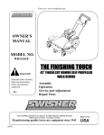
swisherinc.com
OWNER’S
MANUAL
MODEL NO.
T11544
START SERIAL # L205-006001
ENDING SERIAL #: L205-031000
T11044
START SERIAL # L205-045001
ENDING SERIAL #: L205-031000
T10544BSPB
START SERIAL # L205-021001
ENDING SERIAL #: L205-031000
T12544
44” FINISH CUT
TRAILMOWER
START SERIAL # L205-024001
ENDING SERIAL #: L205-031000
T1144HSP
START SERIAL # L205-046001
ENDING SERIAL #: L205-031000
IMPORTANT
Read and follow all Safety
Precautions and
Instructions before
operating this equipment.
Rev 05-136
Assembly
Operation
Service and Adjustment
Repair Parts
1602 CORPORATE DRIVE, WARRENSBURG, MISSOURI 64093
FAX 660-747-8650
PHONE 660-747-8183
Manufacturing quality lawn care equipment since 1945
10662
Made In The
USA
LIMITED WARRANTY
The manufacturer’s warranty to the original consumer purchaser is: This product is free from
defects in materials and workmanship for a period of one (1) year from the date of purchase
by the original consumer purchaser. We will repair or replace, at our discretion, parts found to
be defective due to materials or workmanship. This warranty is subject to the following
limitations and exclusions:
1) Engine Warranty
all engines utilized on our products has a separate warranty
extended to them by the individual engine manufacturer. Any
engine service difficulty is the responsibility of the engine
manufacturer and in no way is Swisher Mower Co., Inc. or its
agents responsible for the engine warranty. The Briggs &
Stratton Engine Service Hot-Line is 1-800-233-3723. The
Tecumseh Engine Service Hot-Line is 1-800-558-5402.
2) Commercial Use
the warranty period for any product used for commercial or rental
is limited to ninety days from the date of original purchase.
3) Limitations
this warranty applies only to products, which have been
properly assembled, adjusted, and operated in accordance with
the instructions contained within this manual. This warranty
does not apply to any product of Swisher Mower Co., Inc., that
has been subject to alteration, misuse, abuse, improper assembly
or installation, shipping damage, or to normal wear of the
product.
excluded from this warranty are normal wear, normal
adjustments, and normal maintenance.
4) Exclusions
In the event you have a claim under this warranty, you must return the product to an
authorized service dealer. All transportation charges, damage, or loss incurred during
transportation of parts submitted for replacement or repair under this warranty shall be borne
by the purchaser. Should you have any questions concerning this warranty, please contact us
toll-free at 1-800-222-8183. The model number, serial number, date of purchase, and the
name of the authorized Swisher dealer from whom you purchased the mower will be needed
before any warranty claim can be processed.
THIS WARRANTY DOES NOT APPLY TO ANY INCIDENTAL OR CONSEQUENTIAL
DAMAGES AND ANY IMPLIED WARRANTIES ARE LIMITED TO THE SAME TIME
PERIODS STATED HEREIN FOR ALL EXPRESSED WARRANTIES. Some states do not
allow the limitation of consequential damages or limitations on how long an implied warranty
may last, so the above limitations or exclusions may not apply to you. This warranty gives
you specific legal rights and you may have other rights, which vary from state-to-state. This is
a limited warranty as defined by the Magnuson-Moss Act of 1975.
2
SAFETY PRECAUTIONS
This Safety Alert Symbol indicates important messages in this
manual. When you see this symbol, carefully read the message that
follows and be alert to the possibility of personal injury.
Read this manual completely. This machine can amputate hands, feet, and throw
objects. Failure to observe the following safety instructions could result in serious
injury or death.
• Read the manual. Learn to operate this machine safely.
• Always disconnect the spark plug wire and place the wire where it cannot
contact the spark plug, to prevent accidental starting of the engine when setting
up, transporting, adjusting or making repairs.
• Keep all shields and guards in
place.
• Understand the speed, steering and stability of this machine. Know the
positions and operations of all controls before you operate this machine. Check
all of the controls in a safe area before starting to work with this machine.
• Allow only responsible adults who are familiar with these instructions to
operate this machine. Never allow children to operate this machine.
• Clear the area of objects such as rocks, toys, wire, etc. that can be picked up
and thrown by the blade.
• Be sure the area is clear of other people before mowing. Be aware of the
mower discharge direction and do not point at anyone. Stop the machine if
anyone enters the mowing area. Children are often attracted to the machine and
the mowing activity. Never assume that children will remain where you last saw
them. Keep children under the watchful care of another responsible adult.
•No riders!
• Do not put hands or feet near or under rotating parts. Keep clear of the
discharge opening at all times.
• Do not mow in reverse. Always look down and behind before and while
backing.
3
• Turn off the blades when not mowing. Before leaving the machine, turn off the
blades and stop the engine.
• Watch for traffic when operating near or crossing roadways.
• Do not operate the mower if it has been dropped or damaged in any manner
or if the mower vibrates excessively. Excessive vibration is an indication of
damage. Repair mower as necessary.
• Dress properly. Do not operate the mower when barefoot or wearing open
sandals. Wear only solid shoes with good traction when mowing.
• Do not operate the machine while under the influence of alcohol or drugs.
• Operate self-propelled machines up and down slopes. There is significant risk
of overturns when operating across slopes. Operate walk-behind machines across
slopes. There is a significant risk of slipping under a walk-behind machine when
operating up and down slopes. Do not operate on slopes greater than 15 degrees.
• Never tamper with safety devices. Check their proper operation regularly.
• Stop and inspect the equipment if you strike an object. Repair, if necessary,
before restarting.
• Never make adjustments or repairs with the engine running.
• Mower blades are sharp and can cut. Wrap the blades or wear gloves, and
use extra caution when servicing them.
4
SAFETY DECALS
Replace decal immediately if damaged. Order by part number from Swisher Mower and Machine Co. Inc.
OD33-Speed Decal
TrailMower Serial #
OD55-Triangle Danger Decal
(All four deck corners)
OD99127-44" Deck White Decal
(Not Pictured)
OD99127-44" Deck White Decal
(Not Pictured)
Engine Serial #
OD15-Void Warranty Decal
OD36-Deflector Decal
OD11-No Step Decal
OD99125-Medium Swisher
Logo White Decal
(Not Pictured)
OD29-Danger Decal
OD103-Single Point Height Adjust Decal
OD45-Warning Decal
5
OPERATING YOUR TRAILMOWER
The operation of any mower can produce foreign objects to be thrown into the
eyes, resulting in severe eye damage. Always wear certified safety glasses or
wide-vision safety goggles over spectacles before staring any cutting machine
and while operating such a machine.
The operation of any cutter produces sound waves that are damaging to the
human ear. Ear protection is recommended.
CAUTION!
Tragic accidents can occur if the operator is not alert to the presence of
children. Children are often attracted to the machine and the mowing
activity. Never assume that children will remain where you last saw
them.
INTENDED USE
The 44” TrailMower is designed to produce a quality finish cut on lawns, golf courses,
etc. It is not intended to clear brush or cut saplings. Your TrailMower should be
towed behind an ATV, golf cart, lawn tractor, or other approved vehicle. It is not
designed for speeds exceeding 5 MPH. WARNING: To avoid serious injury,
operate your mower up and down the face of slopes, NEVER across the face. DO
NOT MOW SLOPES GREATER THAN 15 DEGREES! (See attached guide for
sighting slopes.)
ATTACHING TRAILMOWER TO TOW VEHICLE
• Back vehicle up to desired towing position.
• Offset the TrailMower to the side opposite the tow vehicle discharge (if any).
This prevents the tow vehicle from throwing grass into TrailMower engine.
• Bolt swivel hitch (H10) to tow vehicle receiver. If tow vehicle has a ball hitch,
the ball must be removed before swivel hitch can be fastened.
• Attach tow hitch (4582) to the swivel hitch with hitch pin (H11). Make certain
the hitch pin goes completely through each piece and is clipped to prevent
accidental separation. (FIGURE FOUR)
• Securely attach safety tether (6736) to tow vehicle and to the TrailMower
toggle switch located on right side of the engine. The safety tether will stop the
TrailMower engine either manually or if the two should become separated. It is
very important that the safety tether is securely attached to both the toggle
switch and to the tow vehicle. (FIGURE TWO)
TRANSPORTING MOWER
• Stop TrailMower.
• Place TrailMower deck in its highest position.
• When transporting unattached from tow vehicle, remove spark plug wire
and place it where it cannot contact the spark plug.
6
ENGAGING BLADES (without T-handle option, Standard)
The TrailMower will not start if the blade lever is in the “ENGAGED” position.
• Engage blades by rotating blade lever into the “ENGAGED” position.
• Rotate blade lever in opposite direction to disengage blade.
• The dual braking system is applied when the blades become disengaged. It is
designed to bring the blades to quick stop (approximately 7 seconds). Each
TrailMower brake system has been tested and calibrated. For safety, the
consumer should not alter the braking system.
ENGAGING BLADES (with T-handle option, for order information see detail)
The TrailMower will not start if the T-handle console is in the “ENGAGED”
position.
• Engage blades by pulling T-handle lever into its horizontal position.
• Return lever to its vertical position to disengage blades.
• The dual braking system is applied when the blades become disengaged. It
is designed to bring the blades to quick stop. Each TrailMower brake system
has been tested and calibrated. For safety, the consumer should not alter the
braking system.
STARTING THE ENGINE
See engine manufacturer’s recommendations for the type and amount of oil and fuel
used. Trail Mowers equipped with an electric start engine will need a battery (sold
separately). Swisher recommends using a standard “12N12A” battery.
• Make sure the tow vehicle parking brake is set, mower is level, and blades are
disengaged. Engine must be level to accurately check and fill oil. Do not overfill.
• Check spark plug wire, oil, and fuel.
• Check all electrical connections for build-up or debris.
• Make sure toggle switch is not turned “OFF” and safety tether is attached.
• Set engine Throttle to “Run” position (Rabbit).
•Move the “Choke” Lever to the on position. (Cold engine only)
• With feet clear of mower deck, turn key switch to the “START” position; release
when engine begins to run (12volt models). Recoil models must use pull-rope.
Pull rope with a single fluid motion.
• Set engine throttle at maximum RPM.
• Allow engine to run a few moments before engaging blades.
BREAKING IN YOUR MOWER
• Set vehicle parking brake or chock wheels to prevent accidental rolling.
• Start engine properly.
• Slowly, engage blade control.
• In a safe environment, i.e. no children, allow blades to rotate and engine to
idle for 5 minutes. This breaks in the belts and the engine.
• Stop mower properly.
CAUTION!
SHUT OFF MOWER ENGINE AND REMOVE SPARK PLUG WIRE FROM
SPARK PLUG BEFORE MAKING ANY ADJUSTMENTS TO THE MOWER.
7
MOWER HEIGHT ADJUSTMENT
• Make adjustments while TrailMower is not running.
• There is approximately 1 ½” to 4 ½” of height adjustment.
• Rotate height adjust crank handle(s) in a clockwise direction to lift the mower
deck. A counter-clockwise direction is used to lower the mower deck.
• For best results, see “SUGGESTED PRACTICE” section. Graduated scales
are for reference only, not the actual cutter height.
FRONT TO BACK ADJUSTMENT
For best cutting results, the mowing deck should be raised to ¾” higher in the
rear.
•
•
•
•
Make adjustments while TrailMower is not running.
Remove bolts from the “L” hitch (H1), (SEE FIGURE FOUR).
Raise or lower hitch section to obtain proper front to back adjustment.
Re-install bolts in “L” hitch securely.
TOW HITCH OFFSET
This TrailMower has been designed to operate offset from the center of the tow
vehicle or consecutively with another TrailMower, providing additional cutting width.
When offsetting the mower do so to the side opposite the discharge of the tow
vehicle.
• Swisher recommends if the tow vehicle is equipped with a mid-mount mower
to overlap the cut approximately 6”. This may vary depending on mowing
terrain, obstacles, and/or tow vehicle. Always keep SAFETY the first priority.
• If the tow vehicle is not equipped with a mid-mount mower, we still
recommend offsetting the mower so that the tow vehicle does not crush the
grass.
• To change the offsetting position both ball-lock pins should be removed
(Figure One). The hitches will swivel around remaining bolts. Set hitches to
desired positions and return ball-lock pins, making sure they go thru the hitch
tubing and the semi-circled hole patterned plates.
STARTING TO MOW
•
•
•
•
•
Adjust the cutting height.
Double check vehicle to mower attachment.
Start mower engine and set throttle to “FAST” for best cutting performance.
Slowly engage blade clutch lever.
Carefully mount vehicle and start mowing at a slow travel speed.
STOPPING THE MOWING SESSION
• Bring tow vehicle to a complete stop, shut off engine, and set parking brake.
• Disengage blades.
• Manually shut toggle switch and/or key switch to their “OFF” positions.
• Always remember to remove keys to avoid irresponsible usage. (Electric
Start models only)
8
SUGGESTED MOWING PRACTICES
• Operate mower engine at full throttle to assure the best cutting performance and
maximum material discharge.
• Allow wet grass to dry. Wet grass will clump and collect under the mowing deck.
• Mowing should be started with tow vehicle in low gear and increased only as safe
mowing conditions permit. Mowing speed should not exceed 5 MPH.
• The average lawn should be cut to approximately 2.5” during the cool season and to
over 3” during the hot months.
• For a healthier lawn and better aesthetics, your lawn should be mowed often and
after moderate growth.
• When cutting high or dense grass areas go slowly. Some areas may need to be
mowed twice. The second cut should be at 90 degrees to the first, if possible.
• Mowing thick or high grass: Raise rear of deck to ½” to ¾” above front of the
deck. See “FRONT TO BACK ADJUSTMENT”. When mowing thick or high grass,
it is recommended to cut area twice. The first at a higher setting and the second at the
desired lawn height.
• Creating a manicured lawn: Never cut more than 1/3 of the grass height in one
cutting.
GENERAL TROUBLE SHOOTING
The mower is not cutting level.
•Check air pressure of all tires; make sure they are equal. See tires for
maximum inflation.
• Make certain blades are installed identical, without the engine running.
The engine will not start.
• Disengage blades, turn toggle switch to “OFF” position, check battery and all
other electrical connections, and inspect spark plug and wire (FIGURE
THREE).
• Contact engine manufacturer or qualified mechanic.
Engine runs poorly.
• See engine manual.
• Check the throttle adjuster.
• Replace fuel, clean fuel filter and fuel line.
• Check spark plug and gap.
Mower bounces excessively while towing.
• Lower tire pressure.
• Tow at a slower speed.
IF PROBLEMS PERSIST HAVE A QUALIFIED MECHANIC SERVICE THE
MOWER. NEVER ATTEMPT TO MAKE AN ADJUSTMENT THAT YOU
ARE NOT SURE IS CORRECT. DOING SO CAN CAUSE OTHER
PROBLEMS.
9
MOWER MAINTENANCE
GENERAL RECOMMENDATIONS
The warranty on this TrailMower does not cover items that have been subjected to
operator abuse or negligence. To receive full value from the warranty, operator must
maintain unit as instructed in this manual.
Some adjustments will need to be made periodically to maintain your unit properly.
All adjustments in this manual should be checked at least once each season.
BEFORE EACH USE
• Check engine oil level on a level surface. (Check twice to insure an accurate
reading.)
• Check condition of air filter; clean and replace as necessary.
• Check blade operation; keep blades in good condition.
• Check for loose fasteners and tighten them as needed.
AFTER EACH USE
• Keep blades sharp.
• Remove fresh grass clippings with garden hose.
• Hardened grass clippings on underside should be scraped out with a putty
knife.
• Keep fluids at proper levels.
• Cover unit to prevent rain or other debris build-up. Definitely cover the
engine.
BEFORE AND/OR AFTER EACH SEASON
• Replace the spark plug.
• Clean or replace the air filter.
• A new spark plug and clean air filter assure proper air-fuel mixture and help
your engine run better and last longer.
• Check blades and belts for wear. Replace as necessary.
• Change the oil.
• See engine manufacturer’s recommendations for servicing.
STORAGE RECOMMENDATIONS
CAUTION! Do not store engine indoors or other poorly ventilated area. Keep
engine away from gas appliances and water heaters where fumes could contact
open flame, pilot lights, or sparks.
If engine is to be stored for 30 or more days, prepare unit as follows:
· Drain fuel outside into an approved container.
· Start engine properly and run until unit is out of fuel.
· Let engine cool.
· Remove remaining gasoline from carburetor and fuel tank to prevent gum
deposits from forming within the engine. Gum deposits can cause
malfunction in the engine.
· Store mower with blades disengaged to prevent belts from being permanently
stretched.
10
BLADE CARE AND SERVICE
For best results cutter blades must be kept sharp. The blades can be sharpened with a
few strokes of a file or grinding wheel. Do not attempt to sharpen blades while they are
on the cutter. Disconnect spark plug wire before servicing unit.
Important: Replace blades that have been damaged or deeply nicked.
Important: Check blade and spindle hardware on a regular basis to make sure nuts
are tight.
Only a qualified mechanic should make any
adjustments, disassembly or other kind of repairs.
REPAIR PARTS
Your 44” TrailMower has been produced with components designed specific to this
machine. Although standard V-belts, springs, bearings, blades, pulleys, hardware, etc.
look similar to parts used on other machinery, they may in some cases be made of a
different construction and/or materials.
NOTES:______________________________________________________________
_____________________________________________________________________
_____________________________________________________________________
_____________________________________________________________________
_____________________________________________________________________
_____________________________________________________________________
_____________________________________________________________________
_____________________________________________________________________
_____________________________________________________________________
_____________________________________________________________________
_____________________________________________________________________
_____________________________________________________________________
_____________________________________________________________________
_____________________________________________________________________
_____________________________________________________________________
_____________________________________________________________________
_____________________________________________________________________
_____________________________________________________________________
_____________________________________________________________________
_____________________________________________________________________
_____________________________________________________________________
_____________________________________________________________________
_____________________________________________________________________
_____________________________________________________________________
_____________________________________________________________________
_____________________________________________________________________
_____________________________________________________________________
_____________________________________________________________________
_____________________________________________________________________
11
BALL LOCK PINS
FRONT
LEFT
RIGHT
Left offset shown
REAR
FIGURE ONE
Slide plastic tube snug against
toggle switch.
FIGURE TWO
(FIGURE FIVE FOR DETAILS)
12
T44 RECOIL START
T44 12 VOLT START
FIGURE THREE
WIRING CONFIGURATIONS
PARTS NOT SHOWN
WIRING HARNESSES
B&S ENGINE (Remote Start only)
WH44CHB12V
HONDA ENGINE
REMOTE OPTION
WH1144H
WH44RCH
PULL START W/ B&S ENGINE
10638
TOGGLE/GROUND WIRE ASSEMBLY
9090
BLADE ENGAGE CABLE
9074
12V B&S MANUAL BLADE ENGAGE
10235
12 VOLT MODELS
BATTERY (12N12A) RECOMMENDED
SOLD SEPARATELY
SOLENOID
9043
BATTERY CABLE - POSITIVE
BCSR
BATTERY CABLE - NEGATIVE
BCS
EXTRAS
VELCRO STRAPS
7033
SWISHER DECAL
OD99125
44" DECAL
INTERLOCK MODULE
BATTERY BOX
BATTERY PAD
BATTERY CABLE
BATTERY BOOT
BATTERY HOLD DOWN
OD99127
MOD1
10231
BATPAD
BCL
BCBT
BHOLD
13
1
SEE DETAILS
2
4
15
3 4A
14
16
5
6
5A
7
17
7A
18
28
8
1
9
10
19
11
22
20
29
23
21
23
27
144
30
32
37 145
23
33
24
31
140, 141, 142
38 39
25
143
23
26
34
23A
35
36
FIGURE FOUR
T-HANDLE OPTION
SEE DETAIL
SINGLE POINT HEIGHT ADJUST
ITEM #
1
2
3
4
14
4A
5
5A
6
7
7A
8
9
10
11
12
13
14
15
16
17A
17B
18
19
20
21
22
DESCRIPTION
BELT COVER
MOTOR BASE
1/4 BOLT
HEIGHT ADJUSTER
KNOB
5/16 PAL NUT
5/16 PUSH NUT
ARM
HEIGHT ADJUST ROD
PIVOT BLOCK
FLANGE BEARING
1/2 BUSHING
1/2 BOLT
BEARING CAP
DISCHARGE CHUTE
TORSION SPRING
5/16 NUT
CHUTE MOUNT
5/16 BOLT
5/16 BOLT
COTTER PIN
TIRE/WHEEL
AXLE ASSEMBLY
1/2 BOLT
1/2 NUT
RIGHT ROLLER BRACKET
ANTI-SCALP ROLLER 1/2"
1/2 NUT
5/16 BOLT
HITCH
13
13, 23
PART #
10599*
4517*
NB114
H7K
NB276
NB117
ES214
4006
4007TK
4005
NB177
NB617
4036TK
10598TK
9100
NB181
6030TK
NB136
NB596
NB126
F44157LV
10596TK
NB588
NB118
4016TK
AS003
NB121
NB596
4525TK
* = USE PAINT CODE:
TC=RED,G=GREEN;S=SILVER,TK=BLACK
ITEM #
DESCRIPTION
PART #
23
5/16 NUT
NB170
23A
5/16 BOLT
NB596
24
3/8 NUT
NB182
25
ANTI-SCALP ROLLER 3/8"
AS001
26
3/8 BOLT
NB575
27
HITCH TUBE
4583*
28
3/8 BOLT
NB221
29
3/8 LOCK PIN
NB520
30
FAN HITCH
4582*
31
3/8 NUT
NB182
32
5/16 NUT
NB181
33
SAFETY HITCH PIN
H11
34
5/16 BOLT
NB138
35
L HITCH
H1TK
36
SWIVEL HITCH
H10TK
BOLT/NUT
NB145Z/NB561
37
ROLLER BRACKET
10634TK
38
DECK WELDMENT
10586TC
39
LEFT ROLLER BRACKET
4015TK
140
OILITE BEARING
21008
141
1/2 USS WASHER
NB555
142
1/2-13 BOLT
NB617
143
1/2-13 NYLOK NUT
NB281
144
BACK SKIRT PLATE
4519*
145
FRONT SKIRT PLATE
4518*
EX: 4524RTC; 4525G
12
FIGURE SIX
52
BLADE SET-UP
53
40
55
54
43
44
57
41
45
56
58
46
65A
42
48
55
60
61
47
49
50
59
51
64
63
62
FIGURE FIVE
ENGINE SET-UP
ITEM #
40
41
42
43
44
45
46
47
48
49
50
51
DESCRIPTION
ENGINE
5/16 BOLT
5/16 NUT
TOGGLE BRACKET
SAFETY TETHER
TOGGLE SWITCH
UPPER ENG. SPACER
1/4 X 1 KEY STOCK
ENG. PULLEY
LOWER ENG. SPACER
BELLEVILLE WASHER
7/16 BOLT
OIL DRAIN VALVE & CAP
MODULE & SCREW
PART #
NOT AVAILABLE
NB253
NB170
4483Z
6736
685SP
BB105S
9031
BB105
BB105SL
699
NB452N
AS122/AS123
MOD1/NB137
ITEM #
52
53
54
55
56
57
58
59
60
61
62
63
64
65A
DESCRIPTION
PART #
3/4 NUT
NB175
UPPER BELLEVILLE
AS155
BLADE PULLEY
B4104
THIN WASHER
NB179
BLADE DRIVER
9018
BEARING
B98
4.25" SHAFT
9076
BEARING HOUSING B99ECTK
1/4 BOLT
NB250
1/4 NUT
NB180
22" BLADE
9005
Two Blade Set
9036
BLADE MOUNT PLATE
9008
3/8 NUT
NB216
3/8 BOLT
NB238N
LOWER BELLEVILLE
NB607
3/8 BOLT
NB238
WASHER
B98W
15
65
79
73
67
81
74
78
71
72
70
76
69
68
80
SEE FIG.
NINE
86
87
66
89A
88
84
85
82
75
77
FIGURE SEVEN
75B
T-HANDLE OPTION
84
83
ITEM #
65
66
67
68
69
70
71
72
73
74
75
76
75 B
16
DESCRIPTION
PART #
T-HANDLE LEVER
4463TK
COTTER PIN
NB597
1/4 NUT
NB180
WASHER
NB274
ENGAGE LINK
4461TK
CABLE CLEVIS
9023MOD
5/16 NUT
NB181
CLEVIS PIN
NB518
1/4 BOLT
NB560
5/16 TORX BOLT
NB591
CONSOLE WELDMENT
4602TK
KEY SWITCH (12 VOLT)
3623
KEYS
KSK
T-HANDLE ACCESSORY KIT
4498
BLADE ENGAGE DECAL
OD10
ON/OFF DECAL
OD99
12 VOLT ON/OFF DECAL
OD28
CONSOLE MOUNT PLATE
4601TK
5/16-18 BOLTS
NB138
5/16-18 NUTS
NB181
FIGURE EIGHT
STANDARD ENGAGE
ITEM #
DESCRIPTION
PART #
77
ENGAGE STANDOFF 4547TK
78
5/16 Spade Bolt
NB260
79
1/2 BOLT
NB155
80
ENGAGE LEVER
4548TK
81
HANDLE KNOB
B19BLACK
82
1/4 NUT
NB524
83
1/4 BOLT
NB250
84
1/2 NUT
NB121
85
5/16 BOLT
NB501
86
ENGAGE PIVOT
4578TK
87
5/16 NUT
NB181
88
5/16 NUT
NB170
ON/OFF DECAL
OD10
89A
5/16-18 Nut
NB210Z
* = USE PAINT CODE:
TC=RED,G=GREEN;S=SLIVER,
TK=BLACK
EX: 4547C; 4578S
ITEM #
89
90
91
92
93
94
95
96
97
98
99
99A
100
101
102
103
104
105
106
106A
114
DESCRIPTION
3/8 NUT
WASHER
IDLER PULLEY
WASHER
5/16 SERR FLG BOLT
IDLER SPRING
5/16 NUT
BRAKE LINK
3/8 BOLT
5/16 SPADE BOLT
EYE BOLT
5/16-18 NUT
3/8 NUT
IDLER BUSHING
IDLER BRACKET
1/4 NUT
1/4 BOLT
IDLER SPACER
3/8 BOLT
LOCK NUT
PART #
NB280
NB272
B527
NB556
NB253
4422
NB170
4532
NB107
NB260
V139EB
NB210Z
NB182
6037
4530
NB524
NB218
6040
NB618
NB181
89
106A
90
92
91
94
96
95
106
105
104
97
102
103
99
96
93
101
98
100
99A
FIGURE NINE
Tension Assembly
108
107
110A
113
112
108
110B
109
130
FIGURE TEN
131
Belt / Brake Configuration
132
ITEM #
DESCRIPTION
PART #
107
Belt 74"
4220
108
SPRING
T2SM
109
TENSION BRACKET
4593TK
110A BRAKE ASSY (LEFT)
10591
110B BRAKE ASSY (RIGHT)
10590
111
EYE BOLT
V139EB
112
NEUTRAL SWITCH
3695
8-32 BOLT/NUT
NB 197/NB 201
113
SWITCH BRACKET
4301TK
114
5/16 BOLT/NUT
NB596/NB170
Figure Twelve
Height Adjust
134
132
Item #
130
131
132
134
135
Description
Height Adj Rod
1/2-13 Nut
Bellvile Washer
Machine Bushing
1/2-13 Nylok Nut
Part#
4006
NB213
10635
NB177
NB281
135
17
FIGURE ELEVEN
BRAKE ARM CONFIGURATIONS
Item # Description
118
1/4-20 BOLT
119
1/4-20 NUT
120
BRAKE ARM
121 1/4-20 NYLOCK
122
BRAKE PAD
123
10-24 BOLT
124 10-24 KEP NUT
125
EYE BOLT
128
129
148
18
1/4-20 NUT
1/4-20 BOLT
1/4-20 x 2 BOLT
Part #
NB162
NB524
10589
NB180
9039
NB710
NB172
V139EB
NB180
NB102
NB218
19
44” FINISH CUT
TRAILMOWER
OWNER’S
MANUAL
HOW TO ORDER
REPAIR PARTS:
MODEL NO.
T11544
T11044
T10544BSPB
T12544
T1144HSP
Each TrailMower has its own serial number. Each engine has
its own serial number. The serial number for the TrailMower
will be found on the right hand side of the drive belt housing.
The serial number for the engine will be found on the top of the
blower fan housing.
All TrailMower parts listed herein may be ordered directly
from Swisher Mower & Machine Co. Inc., your nearest
Swisher dealer, or from our website. www.swisherinc.com
All engine parts may be ordered from the nearest dealer of the
engine supplied with your mower.
WHEN ORDERING PARTS, PLEASE HAVE THE
FOLLOWING INFORMATION AVAILABLE:
*
*
*
*
PRODUCT – T-44 FINISH CUT TRAILMOWER
SERIAL NUMBER - _______________
MODEL NUMBER - _______________
ENGINE MODEL NUMBER - _______________
TYPE - _______________
* PART NUMBER
* PART DESCRIPTION
www.swisherinc.com
TELEPHONE - 1-800-222-8183
FAX - 1-660-747-8650
SWISHER MOWER & MACHINE CO. INC.
1602 CORPORATE DRIVE
WARRENSBURG, MO 64093
SWISHER MOWER & MACHINE CO. INC.