1
Geodyna
Optima
Service Manual
All information contained or disclosed in this document is
considered confidential and proprietary by Snap-on Tools
Company. All manufacturing, use, reproduction, and sales
rights are reserved by Snap-on Tools
Company and the
information contained herein shall not be used in whole or
in part without the express written consent of Snap-on
Tools Company.
TABLE OF CONTENTS
Table of Contents
SERVICING THE OPTIMA ............................................................................................... 5-1
INTRODUCTION .............................................................................................................................................. 5-1
THEORY OF OPERATION .............................................................................................................................. 5-1
BFH/OPTIMA SERIES MAJOR COMPONENTS ............................................................................................ 5-4
CAMERA PROCESSOR BOARD ............................................................................................................. 5-4
ELECTRONIC BOX ................................................................................................................................... 5-5
SCANNER / LASER / CCD ....................................................................................................................... 5-6
POWER SUPPLY PCB ............................................................................................................................ 5-6
POWER CLAMP ASSEMBLY .................................................................................................................. 5-7
SELF TEST DURING START UP ..................................................................................................................... 5-8
DISPLAY DESCRIPTION ............................................................................................................................... 5-11
BALANCER SETUP ...................................................................................................................................... 5-11
FUNCTION SCREEN .................................................................................................................................... 5-12
FUNCTION DESCRIPTION ............................................................................................................................ 5-12
CUSTOMER CALIBRATION .......................................................................................................................... 5-14
ENTERING SERVICE MODE ........................................................................................................................ 5-16
C CODES ..................................................................................................................................................... 5-17
C28 DISPLAY AND CLEAR ERROR CODES .......................................................................................... 5-17
C43 RESET COUNTERS ........................................................................................................................ 5-18
C47 SELECT MACHINE MODEL ............................................................................................................ 5-18
C55 INCOMING LINE VOLTAGE ............................................................................................................. 5-18
C56 CIRCUIT STATE OF THE WHEEL GUARD ...................................................................................... 5-18
C57 VIBRATORY TEMPERATURE SENSOR ......................................................................................... 5-18
C60 MOTOR RPM .................................................................................................................................. 5-18
C74 POSITION COUNTER AND BASIC INCREMENTAL SHAFT ENCODER TEST ................................. 5-18
C75 DISPLAY VALUES OF A/D CONVERTER ....................................................................................... 5-19
C80 GEODATA ARM ADJUSTMENT / CALBRATION ............................................................................... 5-20
C81 MEASURING ADAPTER FLANGE AND ZERO PLANE ................................................................... 5-22
C83 CALIBRATION OF UNBALANCE MEASUREMENT ......................................................................... 5-23
C84 EMPTY SHAFT COMPENSATION .................................................................................................. 5-26
C88 WHEEL WEIGHT POSITIONING ..................................................................................................... 5-27
C90 SAVING CALIBRATION DATA .......................................................................................................... 5-28
C98 POWER CLAMP ENCODER ........................................................................................................... 5-28
C110 VCC VOLTAGE .............................................................................................................................. 5-29
C120 ENABLE / DISABLE LASER POINTER ......................................................................................... 5-29
C122 SCANNER / LASER / CCD CALIBRATION .................................................................................... 5-30
C123 DIAGNOSTIC FUNCTIONS ............................................................................................................ 5-32
ACCESSING THE DIAGNOSTIC FEATURES ......................................................................................... 5-32
DIAGNOSITC BITS (SHOWN IN BLACK) ................................................................................................ 5-35
STATUS FLAGS (SHOWN IN BLUE) ...................................................................................................... 5-36
ANALOG INPUTS: (SHOWN IN GREEN) ............................................................................................... 5-36
C123 MECHANICAL SCANNER / LASER / CCD ADJUSTMENT ............................................................ 5-37
CCD / LASER / SCANNER INSTALLATION ................................................................................................... 5-39
INNER SCANNER INSTALLATION .......................................................................................................... 5-39
OUTER SCANNER INSTALLATION ......................................................................................................... 5-40
HOOD ADJUSTMET ............................................................................................................................... 5-40
OUTER SCANNER INSTALLATION CONTINUED .................................................................................... 5-41
REAR SCANNER INSTALLATION ........................................................................................................... 5-42
REAR SCANNER DRIVE BELT .............................................................................................................. 5-43
FIELD PROGRAMMING THE CAMERA PROCESSOR PCB ........................................................................ 5-44
Effective
07/2006
TABLE OF CONTENTS
REMOVING THE BELL HOUSING ................................................................................................................ 5-45
IMPORTANT BALANCER INFORMATION ..................................................................................................... 5-46
QUALIFYING THE BALANCER ..................................................................................................................... 5-46
APPENDIX A .................................................................................................................... A-1
CODES ............................................................................................................................. A-1
KERNEL CODES ........................................................................................................................................... A-1
H CODES SYSTEM IV ................................................................................................................................... A-7
E CODES SYSTEM IV ................................................................................................................................... A-7
Effective
07/2006
SERVICING THE
OPTIMA
INTRODUCTION
The BFH/Optima Series system is a wheel balancing machine equipped with three optical scanners. Two
scanners capture images of the wheel rim profiles (inner and outer), so that the co-ordinates of optimum
positions for application of the balancing weights can be calculated automatically and without user inputs.
The scanners are also used to obtain geometrical data about rim deformations, deviation of the rim edges
from its axis of rotation (Rim Runout). The third scanner provides geometrical data about tire deformations,
deviation of the tire from its axis of rotation (Tire Runout). Such data is used for advanced diagnosis of the
wheel as well as to provide the user with indications on how to proceed in order to minimize the effects of
such deformations.
THEORY OF OPERATION
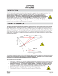
The BFH/Optima Series system is based on distance measuring devices (range finders) based on the
principle of LASER triangulation. This device comprises a LASER source, a lens and a linear optical image
sensor (a CCD – charge coupled device). The beam of coherent light emitted by the LASER source hits the
object whose distance is to be measured. The beam of light is diffused (scattered) in a plurality of light rays
from the surface of the object and the rays are concentrated by the lens in a spot on the sensitive surface of
the linear optical image sensor. The position of the spot on the sensor is determined by a digital analysis of
the electrical signal produced by the sensor.
The distance between the object and the LASER source may be calculated. In practice, a calibration
procedure is performed and a polynomial interpolation of a suitable degree is used. Specifically, the BFH/
Optima system implements cubic spline interpolation with shape preserving characteristics.
The complete process is as follows:
1. Laser power – exposure time settling. The system is able to set the optimum values of laser power
and CCD exposure time according to the ambient light, amount of reflected light, and reflectivity of
objects.
2. Background subtraction. Two successive readings are taken: in the first the laser source is off, in
the second is on. Complete sensor readouts are kept in the computer’s memory. The difference of
the acquired data provide an image of the CCD sensor without effects due to ambient light.
3. Detecting the position of the light peak on the linear optical image sensor.
4. Calculating the distance to the object by means of polynomial interpolation.
Effective
07/2006
Page 5-1
BFH / OPTIMA
Profiling
In the BFH/Optima Series system, the distance measuring devices (range finders) are rotated in a plurality
of known positions by a stepper motor, so that they constitute optical scanners. The scanners, detecting the
distances from a known position of a plurality of points on the object to be explored (the wheel rim) allows
the spatial co-ordinates of each point detected to be obtained.
For each scanner, the complete process is as follows:
1. Measuring the distance to the point hit.
2. Saving the distance measured at point 1 and the position of the distance measuring device at point 1.
3. Moving the laser range finder to the next known position.
4. Repeating steps 1 – 4 until the scan is complete.
Based on these co-ordinates, it is possible to identify positions on the rim profile which are useful, and even
in a certain sense optimum, for the application of balancing counterweights. The co-ordinates of these
positions are calculated automatically and without contact.
The complete weight position detection process is as follows:
1.
2.
3.
4.
5.
6.
7.
Scan rim contour to determine typical rim parameters
Compare current rim pattern with a set of stored rim patterns
Select the best match stored rim pattern
Pick pre-established weight locations associated with the best match pre-established rim pattern
Calculate weight amount and display
Allow the user to modify suggested weight location by moving the laser pointer
“Learn” from experience
Page 5-2
Effective
10/2006
BFH / OPTIMA
Rim Runout Measurement - Rim- Tire Matching / Optimization
It is known that the vibrations produced by a motor vehicle wheel as it turns are caused, by the following:
1.
2.
3.
4.
5.
Uneven distribution of weights on the tire
Uneven distribution of weights on the rim
Geometrical deformation of the tire
Geometrical deformation of the rim
Uneven tire elasticity (variation in stiffness)
The BFH/Optima system allows the identification of geometrical deformations in the rim, that is to say,
deviation of the rim axis from its axis of rotation:
Radial and Lateral Runout.
The scanner devices are rotated to a known position so that the LASER beam hits the surface of the rim at a
predetermined point. The rim is rotated about the wheel balancer shaft and a plurality of distance measurements are taken at known rim angles of rotation. The operation is repeated for at least one other known
distance measuring device position. On the basis of the data gathered in this way, a calculation process
defines the eccentricity (Radial Runout) and angle (Lateral Runout) of the rim axis relative to the axis of
rotation. This data can be used to provide the user an indication of the quality of the rim examined. It is also
used to provide the user with indications on how to position the tire relative to the rim in order minimize the
effects of such deformations.
In fact, the system allows the measurement of geometrical data relative to tire deformations, deviation of the
tire axis from its axis of rotation. The distance measuring device is moved by rotation and translation to a
known position so that the LASER beam hits the surface of the tire at a predetermined point. The wheel is
rotated about the wheel balancer axis and a plurality of distance measurements are taken at known wheel
angles of rotation. On the basis of the data gathered in this way, a calculation process defines the eccentricity
– Radial Runout – of the wheel axis relative to the axis of rotation. A calculation process defines the eccentricity of the tire only, based on the measurements taken respectively on the rim and on the entire wheel by
means of vector subtraction.
This data, together with the data about the imbalance and the data about the rim geometrical deformations,
allows a complete wheel diagnosis and provides the user with more accurate indications. Moreover, a suitable optimization algorithm provides indications on how to position the tire relative to the rim in order to
minimize the concurrent effects of such deformations in accordance with appropriate criteria. Typically, the
tire is rotated with respect to the rim opposing the peak (maximum) of the
tire radial runout with the minimum of the rim radial runout, thus minimizing the radial runout of the assembled
wheel.
Effective
10/2006
Page 5-3
BFH / OPTIMA
BFH/OPTIMA SERIES MAJOR COMPONENTS
This section identifies the major components for the BFH/Optima Series balancer. All descriptions and AC/
DC theory of other components can be found in earlier chapters of this service manual.
CAMERA PROCESSOR BOARD
The Camera Processor board is the liason between the three Scanner / CCD assemblies and the Main
Processor PCB inside the Ebox.
J6/7/8/9
Pin #
1
2,5
3
4
6
J10
Pin #
1
2
3,4
J11
Pin #
1
2,4
3
J12
Pin #
1,2,4,6
3,5,13,14
7,8,9,10
11
12
J13
Pin #
1,2,3
4,5,6
Page 5-4
Direction
Digital Out
Power Out
Digital Out
Digital Out
Digital Out
Name
Q3
Un
Q4
Q2
Q1
Description
Stepper Motor Phase B
Common Power Supply
Stepper Motor Phase D
Stepper Motor Phase C
Stepper Motor Phase A
Direction
Power Out
Digital In
Name
+5Vdc
Zpos3
Description
Digital Power Supply (5V)
Motor 3 Zero Position
dGnd
Digital Ground
Direction
Digital In
Name
PH-A
Digital In
PH-B
Description
Encoder Phase A
dGnd
Digital Ground
Encoder Phase B
Direction
Power In
Name
Digital In
Digital I/O
Direction
Power In
NC
IIC-SCif
IIC-SDif
Name
Description
External 5V power supply
External Ground
Not Connected
External IIC Serial Clock
External IIC Serial Data
Description
External Motor Power Supply
External Motor Ground
Effective
10/2006
BFH / OPTIMA
J14,15,16
Pin #
1,18,20
2
3
4,12
5
6
7
8,10
9
11
13
14,16
15
17
19
Direction
Analog In
Analog In
Power Out
Digital Out
Out
Digital Out
Power Out
Digital In
Digital In
Digital I/O
Digital Out
Digital Out
Digital In
Digital Out
Name
Description
Digital Ground
OSx
OS CCD signal
DOSx
DOS CCD signal
+5Vd
5V Digital Power Supply
FRMstx
Frame Start Signal
LPx
Laser Pointer Switch
RSTx
Reset signal
+3.3Vd
3.3V Digital power supply
AUXoutx Auxialiary Digital out
CONVstx Conversion start signal
SDA
IIC serial data
E0/1
IIC EEPROM address configuration
SCL
IIC serial clock
Zposx
Scanner home position signal
LASERx Laser modulation signal
J10
Rear
Encoder
Zero
J13
Motor
Power
J12
PCB
Power
J11
Power
Clamp
Encoder
J9
Rear
Scanner
Motor
Drive
J8
Rear
Scanner
Motor
J7
Outside
Scanner
Motor
J6
Inside
Scanner
Motor
J16
Rear
CCD
J15
Outside
CCD
J14
Inside
CCD
ELECTRONIC BOX
The BFH/Optima is equipped with an electronic box somewhat like the Y2k balancers. Additional components have been added to the power supply pcb to operate the “Power Clamp” and the “Power Clamp
switch”. The box is backwards compatible but the older Ebox will not work in the BFH/Optima balancer.
Effective
10/2006
Page 5-5
BFH / OPTIMA
SCANNER / LASER / CCD
The BFH/Optima is equipped with 3 Scanner assemblies. Each of these assemblies are installed and
calibrated as complete assemblies. A role call is performed with each one on boot up. There are no
serviceable components on these assemblies with the exception of the manufactures mechanical
adjustments. DO NOT ATTEMPT TO MAKE ADJUSTMENTS OTHER THAN THE ZERO REFERENCE
STATED LATER IN THIS MANUAL. Each scanner assembly has a zero stop that has minor adjustment.
The rear scanner assembly and the outside scanner assembly are identical and can be swapped. However,
the inside scanner assembly has a different mounting bracket and cannot be interchanged with the other two
assemblies. For troubleshooting purposes the units can be swapped at board level. Should any of these
assemblies require replacement the balancer will flag an E360 error code and force a scanner calibration.
POWER SUPPLY PCB
The Power Supply PCB receives 230VAC power from the Electronic box. This voltage can be measured
using a Digital Volt Meter at J1 pins 1 and 2 on the Power Supply PCB. The AC power passes through onboard bridge rectifiers converting the power to 9VDC which is used to power all of the (4) Scanner Motors.
This 9VDC can be measured at J2 pins 1,2 and 3. Pins 4,5 and 6 are ground connections. This voltage must
be adjusted after the installation of the Power Supply PCB. Follow the procedure below to measure and
adjust the output voltage to the scanner motors.
1.
2.
3.
Remove the weight tray
Place the positive lead of the Digital Volt Meter on Pin 1 (Red wire) and the negative lead of the Digital
Volt Meter on Pin 6 (Black wire).
Use a small pocket screwdriver and adjust the pot to obtain a voltage reading between 9 - 9.5 VDC.
Adjustment Pot
Pin 6
Pin 1
Page 5-6
Effective
10/2006
BFH / OPTIMA
POWER CLAMP ASSEMBLY
The BFH/Optima series balancer is equipped with a power clamp that eliminates the need for a standard or
quick clamp nut. The Power Clamp is activated by lifting up on the foot pedal mounted on the balancer. The
vibratory system has an optical sensor mounted on the shaft that senses variation on a visible encoder disk.
The opti switch looks to see if the shaft is spinning before operating the power clamp. The power clamp will
not open or close if the shaft is spinning. The large pulley drives the power clamping jaws while the magnetic
brake is engaged and is holding the shaft. Should the clamping jaws be engaged during the event of a power
failure there is a manual overide to disengage the power clamp so the wheel/tire assembly can be removed.
Manual Overide Wheel and Tire Removal Procedure
1.
2.
3.
4.
5.
On the front of the balancer, remove the plug from the access holes.
Insert a large screwdriver into the access hole approximately 6 inches.
Slowly turn the Wheel and Tire assembly CW until the “Manual Stops” make contact with the screwdriver.
Continue to turn the Wheel and Tire assembly until the power clamp cup reaches the end of the shaft.
Once power is resumed simply lift up on the foot pedal to re-engage the power clamp mechanism.
Access Hole
Manual Stops
Effective
10/2006
Page 5-7
BFH / OPTIMA
SELF TEST DURING START UP
The BFH/Optima performs a start-up routine when power is applied. A series of self diagnostic tests is
conducted after the machine has been turned on. If a test is not successful: a series of audible signals is
given, or
an error code is displayed. A three-tone signal is given once, the machine is operative. In case
there is a functional error, it must be acknowledged by pressing the STOP or ESC key to proceed.
Listed below are the steps that the balancer performs along with possible “E Codes”, “C Codes”, or “H Codes
that could occur. This is for informational purposes.
1.
Communication between microcontroller and embedded PC
(Blue screen)
Service Codes: No service code available
Communication between micro-controller and embedded PC is not OK (check connecting cable). This
can also indicate a bad connection to the keyboard. Check cabling between embedded PC and processor or cable to switches on the front panel.
2.
Check availability of keyboard
(E 300)
Service Codes : No service code available
The microcontroller was not able to detect a keyboard. Check cabling between microcontroller and
keyboard.
3.
Check content of permanent memories (E 145)
Service Codes: C85, C86 to copy content of permanent memory
Contents of both permanent memories are different, but both contain valid data. If the trouble signalled
by the error code is not remedied (using service codes C85 or C86), the machine will remain in service
code mode. It will be necessary to perform a manufatures calibration (C83, C84, C88)
4.
Check model information (E 900)
Service Codes : C47 to set model
The stored machine model is not known. If the trouble signalled by the error code is not remedied (using
service codes C47), the machine will remain in service code mode.
5.
Check keyboard (E 89)
Service Codes : No service code available
One of the keys F1 to F6, HELP, ESC, START supplies a key code. The machine will proceed with the
next step only if the trouble is remedied.
6.
Check pedal switches
(E 89)
Service Codes : C56 to check the pedal switches.
C75, AdC16 to check voltage to external switches. (See “C75”)
One or, if available, both pedal switches are actuated. The user can now remedy the trouble. Press
STOP or ESC key to check the pedal switch once again and to delete the error code reading. If the
trouble cannot be remedied, the pedal is made inoperative.
7.
Check BFH/Optima Calibration
(E 360)
Service Codes : All codes available for this model
The BFH/Optima hardware requires wheel profiler position calibration.
When the camera controller board is replaced on the machine, the software detected that calibration data
is missing.
Calibration procedure C122 is required to calibrate the actual position of the laser scanners with respect
to the balancer reference plane.
Page 5-8
Effective
10/2006
BFH / OPTIMA
8.
Check BFH/Optima Hardware
(E 361)
Service Codes: All codes available for this model
Wheel profiler is not present or responding during the self test. The balancer controller board was not
able to communicate with the camera controller board during start-up test.
Possible causes:
•The camera controller board is missing or dead.
•The cable connecting the balancer controller board and the camera controller board is un
plugged, damaged or missing.
9.
Check BFH/Optima Hardware
(E 362)
Service Codes : All codes available for this model
Main camera board self test failed.
Balancing is not possible since wheel data cannot be scanned.
Problem during power up. Switch power off and on again. Possible camera board failure.
10. Check BFH/Optima Inner Scanner
(E 363)
Service Codes : All codes available for this model
Left side scanner self test failed or CCD not calibrated or zero mark not detected.
Balancing is not possible since wheel data cannot be scanned.
11. Check BFH/Optima Outer Scanner
(E 364)
Service Codes : All codes available for this model
Right side scanner self test failed or CCD not calibrated or zero mark not detected.
Balancing is not possible since wheel data cannot be scanned.
12. Check BFH/Optima Rear Scanner
(E 365) (Excluding 800)
Service Codes : All codes available for this model
Rear scanner self test failed or CCD not calibrated or zero mark not detected.
Wheel data can be scanned, balancing is possible. Runout measurement of the wheel is not possible.
13. Hardware tests C1- --- If an error occurs during the hardware test. The four hyphens replace the digits 0 to 9 and the letters A to
F which all characterize an error/defect. Refer to all Error Codes in Appendix A
The following test are performed:
A. Power supply voltage (235V)
B. 5V line
C. Incremental encoder (Current of optoelectronic LED)
D. Transducer signal available
E. Auto Stop System (Voltage for relay on Motor Control Board)
A. Hardware test - common errors
C10F02 - Test returned with an error. No valid test results available
C10F07- Test function reported an unkown error
C10F18- Test timed out. No valid test results available
B. Hardware test - Power supply voltage
C10800
C10801
C10804
Service Codes: C55 to check line voltage.
If the line voltage is below or above a limit the error code is displayed. (See “C55”)
Effective
10/2006
Page 5-9
BFH / OPTIMA
C. Hardware test - 5V line
C10810
C10811
Service Codes: C110 to check 5V voltage.
If the 5V voltage is below or above a limit the error code is displayed.
D. Hardware test - Current of optoelectronic LED
C10705
C10706
C10707
C10708
Service Codes: C75, AdC1 to check LED
If the current / voltage is below or above a limit the error code is displayed.
E. Hardware test - Transducer signals
C10410
C10420
C10430
Service Codes: C103/C104 to check transimpedance and signal amplifiers and transducer values.
If no signals from the transducers are detected the error code is displayed.
F. Hardware test - Auto stop system
C10380
C10381
C10382
C10383
Service Codes: C75, Adc21 to check voltage on capacitor of the auto stop system.
If the voltage is below or above a limit or the recharging time is above a limit the error code is displayed.
14. Hardware test disturbed
H 82
Service Codes : All codes available for the model
A self test was disturbed (e.g. wheel was rotated during the transducer test)
The code is displayed for 3 seconds, then measurement is repeated (10 times maximum), or aborted
using the STOP or ESC key.
15. Power clamp service interval expired
E93
All codes available for this model.
After a successful boot up the following screen will appear on the display.
Page 5-10
Effective
10/2006
BFH / OPTIMA
DISPLAY DESCRIPTION
The Display of the BFH/Optima Series balancer is divided into three parts. Each of these parts display
different information throughout the use of the balancer.
•
•
•
Main Screen: Main information screen for the user interface.
Function Key area:
Six function keys F1 to F6, the functionality of the keys can change in every
screen. Represents the function of the keys on the keyboard.
Status Area: Status information from top to bottom, balancer model and software revision, date and
time, screen name, balancer status (i.e. adapter compensation active, loaded user), error messages.
Status
Area
Main
Screen
Function
Key
Area
BALANCER SETUP
On the initial installation the balancer should be
setup for the customer preferences i.e. ounce/
gram, day/month/year, time, etc. Press the
“Function” key (F1)
Start = No Function
Stop = Stop the Main Shaft
Escape = No Function
Help = Go to Help Screen
F1 = Go to Function Screen / Enter Service Mode
User Calibration / Text Editor
F2 = Adapter compensation function or if adapter
compensation is active; switch off. The unbalance of an adapter can be temporarily compensated with this function. If the adapter compensation is active it is indicated by the adapter compensation icon in the status area. (Operator
Manual)
F3 = No Function
F4 = Go to Balancing Function (Operator Manual)
F5 = No Function
F6 = Optima menu (Operator Manual)
Effective
10/2006
Page 5-11
BFH / OPTIMA
FUNCTION SCREEN
Start = No Function
Stop = Stop the Main Shaft
Escape = Back to Introduction Screen
Help = Go to Help Screen
F1 = User Calibration
F2 = Go to text editor
F3 = No Function
F4 = No Function
F5 = Used to toggle selected Function
F6 = Used to change selected Function
While pressing and holding in the <F6> key rotate
the shaft. The green indicator arrows in the “Main
Screen” area will either move up or down depending on the direction of the shaft rotation. Once the
indicating arrow reaches the function to be
changed release the “F6” key. Press and hold the
<F5> key to toggle the function. The indicator
arrow at the bottom of the “Main Screen” area
indicates additional information. The two “--”
marks at the top of the Main Screen area indicates that there is no information above the
selected function.
FUNCTION DESCRIPTION
Balancer operating mode.
Saving the operating mode setting in the non volatile memory. The saved setting are now active after the next
power on.
• 0: manual (The BFH/Optima must be set to the manual mode before running any C-Codes.)
• 1: profiling
• 2: optima
Setting factory default modes of operation.
• Set to 1 for changing all setting to factory defaults and settings.
Saving modes of operation in permanent memory.
Saving the user settings in the non volatile memory. The saved setting are now active after the next power on.
• 0: do not save
• 1: save settings
After successful write to the non volatile memory the display board speaker sounds the typical Snap-on “TüDüLü”.
Language selection.
• The English Language is the first one on the list.
The volume of audible signals.
• 0 ... 100: selectable from 0 (off) to 100 (loud), 50 is default.
Resolution of unbalance amount readings.
The resolution of the unbalance display.
• Normal: rough, default 5 gram / .25 ounces
• Fine: fine 1 gram / .05 ounces
Page 5-12
Effective
10/2006
BFH / OPTIMA
Suppression of minor unbalance readings.
The user threshold can be changed with C8. Below this threshold the unbalance value is set to zero.
• off
• on, default
Setting threshold value for unbalance suppression.
Threshold value for suppression of minor unbalance readings.
•
3.5 ... 20.0 grams, 3.5 grams is default
•
0.25 ... 2.00 ounces, 0.25 ounces is default
All unbalance values below the threshold are set to zero if suppression of minor unbalances is enabled. If the
right, left and static unbalance values are set to zero the OK segment is on. If the ALU mode is not normal the
unbalance values are transformed to the normal ALU mode to check the values.
Measurement units of the unbalance amount readings.
• grams, default
• ounces
Number of revolutions for a measurement run.
Note that a decrease of the number of revolutions for a measurement run can cause an in-accuracy of the
measurement results.
• 5 ... 25: Number of revolutions for a measurement run, 10 is default.
Starting a measuring run by closing the wheel guard.
This feature does not work in the user codes, service codes, optimization and minimization.
• off, default
• on
Automatic braking when wheel guard is raised.
• off: no automatic braking, motor is switched off.
• on: braking to standstill, default.
Releasing of the power clamping device.
The power clamp system can be locked. This can be used if a special clamping device is in use.
• off: no lock, default
• on: locked
Actuation direction of pedal for clamping/releasing.
The functionality of the power clamp foot pedal can be changed.
• raise: raise pedal for clamping, default
• press: press pedal for clamping
Three lines for changing the date.
• Day: dd.—.—
• Month: —.mm.—
• Year: —.—.yy
Two lines for changing the time.
• Hour: hh:—
• Minute: —:mm
Effective
10/2006
Page 5-13
BFH / OPTIMA
The balancer has counters to count the measured runs.
The counters are displayed in three lines:
• number of measurement runs / number of measurement runs with OK
• number of measurement runs since last calibration / number of clamping.
• number of optimization and minimization / number of measurement runs in service mode
Screensaver timeout (0=disable)
• Amount of time for screensaver to activate while unit is sitting idle (default 20)
CUSTOMER CALIBRATION
The BFH/Optima balancer features a simple user calibration program. Perform this procedure when the
balancer has been moved, disturbed, or whenever accuracy is questioned. Occasional field calibration will
ensure years of reliable service.
1. Press and release the <Function> key (F1)
from the “Intro Screen”.
2.
Press and release the <Calibration> key
(F1).
Page 5-14
Effective
10/2006
BFH / OPTIMA
3. With nothing mounted on the shaft lower the wheel
guard and press the <SPIN> key. The balancer
should spin and come to a complete stop.
4. After the balancer comes to a stop raise the wheel
guard and screw the calibration slug into left side
of the flange plate. Lower the wheel guard and
press the <SPIN> key. The balancer should spin
and come to a complete stop. Once the shaft
stops the display should display “OK” and the
speaker sounds the Snap-on “TüDüLü”.
Calibration Complete
Effective
10/2006
Page 5-15
BFH / OPTIMA
ENTERING SERVICE MODE
1.
From the Introduction Screen press the <FUNCTION> key (F1) to enter in to the Function Menu.
2.
By pressing the <F6> key 3 times successively the
“SERVICE” key (F4) will become active.
NOTE: BEFORE PERFORMING ANY “C-CODES”
ON THE BFH/OPTIMA BALANCER THE
TECHNICIAN MUST FORCE THE BALANCER INTO THE MANUAL MODE. SEE
“BALANCER OPERATING MODE” UNDER
“FUNCTION DESCRIPTION EARLIER IN
THIS CHAPTER.
3.
By pressing the <F4> key the service program will
become active.
Page 5-16
Effective
10/2006
BFH / OPTIMA
C CODES
By pressing and holding the <C-CODE> key (F1) and rotating the main shaft the user can select the desired
C-Code. Once the desired C-Code is displayed in the C-Code identifier window the technician needs to
simply release the “C-Code” key (F1). After each C-Code change it is recommended that the technician save
the change by use of the “C90” code. Many codes are written for engineering purposes and are not valid for
field use.
C
Description
28
43
47
55
56
57
59
60
74
75
76
80
81
83
84
85
86
88
90
98
110
120
122
123
Display and clear error codes
Reset counters
Select machine model
Indication of the line voltage
Indication of the circuit state of the wheel guard switch
Indication of temperature
Indication of the residual unbalance compensated for using code C84
Motor: Indication of the RPM of main shaft
Indication of the position counter and basic incremental encoder test
Display values from AD converter
Indication of the voltages used by the 2 step motor control
Geodata arm adjustment and calibration (Hofmann Optima only)
Geodata arm calibration (Hofmann Optima only)
Calibration of the unbalance measurement with wheel/test rotor.
Compensation of unbalance of main shaft
Copy content of serial EEPROM (EEP) from micro-controller EEP to incremental encoder EEP.
Copy content of serial EEPROM (EEP) from incremental encoder EEP to micro-controller EEP.
Calibration of the 12 o’clock position for positioning the weights on the wheel.
Saving the adjustments data
Display angular position of power clamp pulley, incremental encoder test.
Indication of the operating voltages supplied by the power supply module.
Enable / Disable the laser pointer
Calibration of the Scanner / Laser / CCD assemblies (Inner, Outer and Rear).
Manufacturing diagnostic and mechanical adjustment test.
C28 DISPLAY AND CLEAR ERROR CODES
The last 10 different malfunction codes are written into the error memory so that they can be called up and
reported by the operator of the wheel balancer e.g. for remote diagnosis of malfunctions. The most recent
malfunction code is written into memory location 1 and the previous error codes are shifted to the higher
memory locations. Displays the internal error code (6 digits).
NOTE: MAKE SPECIAL NOTE OF DIAGNOSTIC CODES THAT RELATE TO A SPECIFIC COMPONENT. REPEATED DIAGNOSTIC CODES POINT TO THE FAILED COMPONENT.
Use the “Enter” key (F4) to proceed to the next error message (reading Err1 -Err10). If no error occurred, “—
” is displayed. Clearing the entire error memory (step 2): Press the Acknowledgment key to proceed to step
2. Use the option selection to choose “1” and acknowledge with the “Enter” key (F4).
Effective
10/2006
Page 5-17
BFH / OPTIMA
C43 RESET COUNTERS
This C-Code is used to reset all balancer counters. The following counters are reset. This code will not
clear any error codes that have been set into memory.
• Total number of measuring runs
• Number of measuring runs where balance quality was considered OK
• Number of optimizations and minimizations
• Number of measuring runs in service mode
• Number of measuring runs since the last calibration
0: No reset of counters
1: Reset of counters
C47 SELECT MACHINE MODEL
This balancer is sold world wide under different brands and model numbers. To validate any software
upgrades. Enter C47, press the <F4> key followed by pressing the <F6> key, the balancer will reboot after a
few seconds.
C55 INCOMING LINE VOLTAGE
Measured line voltage going into the electronic box. The correct voltage is 230VAC ± 10%.
C56 CIRCUIT STATE OF THE WHEEL GUARD
This test function can be used to determine the angle at which the wheel guard switch trips. With the wheel
guard in the open (up) position the reading should be 000. Slowly lower the wheel guard to the closed (down)
position, the reading will change once to 100 indicating the position of a closed wheel guard.
C57 VIBRATORY TEMPERATURE SENSOR
Measures the vibratory temperature, measurement displayed in Celcius.
C60 MOTOR RPM
Once this code is called up “---” is displayed in the right display. As soon as measured data is available, the
current speed is displayed. The correct value is 190 ± 10 RPM.
C74 POSITION COUNTER AND BASIC INCREMENTAL SHAFT ENCODER TEST
Once this code is called up, the angular position and incremental encoder status register are display continuously. For a short test turn the main shaft at least 2 turns in both directions, the status register
then must show 23F. For detailed status information see below.
Angular position:
As long as the incremental encoder has not yet synchronized with the zero reference, the angular location
reading is “- - -”. After synchronization the angular position is display as a value in a range between 0 and
511.
-00
-07
-0b
-1b
-1F
-27
-2F
after switching power on (main shaft not moved at all), or after pressing the Special function key
after 2 turns backward Æ A- and B channel signals are OK, but there is no synchronisation in backward direction.
after 2 turns forward Æ A and B channel signals are OK, but there is no synchronisation in forward
direction.
after 2 turns forward/ backward Æ A and B channel signals are OK, synchronisation in forward rotation
is OK as well.
after 2 turns in each direction A and B channel signals are OK, but synchronisation was made in
forward direction only
after 2 turns backward Æ A and B channel signals are OK, synchronisation in backward direction is
OK as well
after 2 turns in each direction Æ A and B channel signals are OK, but synchronisation was made in
backward direction only.
Page 5-18
Effective
10/2006
BFH / OPTIMA
23F Incremental encoder was rotated by more than 2 turns in each direction and performs properly.
>-40 Synchronisation error in forward direction
>-80 Synchronisation error in backward direction
Comments
If this test fails (no 23F) please check
•
the cabling of the opto electronic – micro-controller
•
the connectors of the cable
•
clean the incremental encoder sleeve
C75 DISPLAY VALUES OF A/D CONVERTER
NOTE: SOME OF THESE CODES ARE NOT USED IN THE BFH/OPTIMA SOFTWARE.
AD input
Channel
Description
AdC 0
0.0
REF-AD
AdC 1
1.0
fLED-CW
AdC 2
2.0
fSON-TMP
AdC 3
3.0
fBAL-TMP
AdC 4
4.0
fANA3
AdC 5
5.0
fANA2
AdC 6
6.0
fANA1
AdC 7
7.0
fPOT
AdC 8
8.0
fPOt-WHO
AdC 9
9.0
fPOT-OFS
AdC 10
10.0
fPOT-DIA
AdC 11
11.0
RF1V23
AdC 12
12.0
VCC-W
AdC 13
13.0
fLINE-V
AdC 14
14.0
AIR
AdC 15
15.0
AIL
AdC 16
5.0
VCSSw*
AdC 17
6.0
AdC 18
5.1
VBrCur*
AdC 19
6.1
AdC 20
5.2
VDisp*
AdC 21
6.2
VAssStat*
AdC 22
5.3
VRimSens*
AdC23
6.3
VRelCur*
AdE 1
AE1
AdE 2
AE2
* via multiplexer on the power interface
Effective
10/2006
Reference voltage of external AD converter
LED current control
Temperature ultrasonic unit
Temperature of transducer/vibratory system
Motor current
Power interface board multiplexer channel Y
Power interface board multiplexer channel X
free
Width potentiometer (not used)
Distance/extraction potentiometer (not used)
Diameter/angle potentiometer (not used)
Internal reference voltage of analogue unit potentiometer
½ voltage of +5V supply
Mains voltage control
Input of voltage amplifier in front unbalance channel
Input of voltage amplifier in rear unbalance channel
0.793 * supply voltage to external switches
free
Coil current of solenoid brake (not used)
free
Supply voltage of display board
Voltage on capacitor of AutoStopSystem
Identification of rim material (not used)
Coil current of relay
External AD converter (rear transducer)
External AD converter (front transducer)
Page 5-19
BFH / OPTIMA
C80 GEODATA ARM ADJUSTMENT / CALBRATION
NOTE: THIS TEST REQUIRES THE USE OF A SPECIAL CALIBRAITON ROD AS SEEN IN STEP 5.
FAILURE TO USE THE REQURIED TOOL WILL RESULT IN A CALIBRATION ERROR.
1.
Enter the “Service” routine and select C80.
2.
The basic settings of .15 to .20 Volt of the diameter
and distance potentiometers are read out.
The left-hand reading refers to the basic setting of
the diameter potentiometer. Engage the calibration
tip of the gauge head with the calibration groove in
the board of the vibratory system. If the slider
voltage of the diameter potentiometer is not within a
range of .15 to .20 Volt, turn the potentiometer shaft
to bring the voltage to within this range.
The right-hand reading refers to the basic setting of
the distance potentiometer.If the gauge arm is in left
home position and if the slider voltage of the distance potentiometer is not within a range of .15 to
.20 Volt, turn the potentiometer shaft to bring the
voltage to within this range. Return the gauge arm
into the left home position and press the <F6>
“ENTER KEY” to store the values.
3.
Fully extend the Geodata arm and hold, press the
<F6> “ENTER KEY” to store the value.
4.
Engage the calibration tip on the bottom of the
Geodata head with the calibration groove in the
vibratory system and press the <F6> “ENTER
KEY” to store the value.
Page 5-20
Effective
10/2006
BFH / OPTIMA
5.
Raise the gauge arm, apply the calibration tip of the
diameter calibration rod into the calibration groove
of the board of the vibratory system and the calibration tip of the gauge arm into the recess at the lower
end of the calibration rod. Pull out the gauge arm
until the calibration rod is in vertical position. Press
the F6 ENTER KEY to store the value.
6.
Step number 5 of the calibration is not programmed.
Press <F6> “ENTER KEY” to continue.
7.
Grasp the Geodata arm and pull it out slowly until it
clamps and hold it. Repeat this procedure 3 times.
When the gauge arm had been pulled out and
clamped 3 times, the reading proceeds
automatically to step 7.
Effective
10/2006
Page 5-21
BFH / OPTIMA
8.
Pull out the gauge arm at least 7 times with increased constant speed until it clamps. After each
clamping hold the gauge arm for at least 1 second
in the instantaneous clamping position
before repeating this procedure. When the
gauge arm had been pulled out and
clamped 7 times, the reading
proceeds automatically with C90 “Save
Calibration Data”.
C81 MEASURING ADAPTER FLANGE AND ZERO PLANE
1.
Enter the “Service” routine and select C81.
2.
Mount the Pruefrotor on the shaft.
3.
Pull the Geodata arm and touch the tip of the arm to
the body of the Pruefrotor and press the <F6>
“ENTER KEY” to store the value.
Page 5-22
Effective
10/2006
BFH / OPTIMA
C83 CALIBRATION OF UNBALANCE MEASUREMENT
This test must be done using a Pruefrotor.
NOTE: THIS TEST REQUIRES THE USE OF A PRUEFROTOR. ALL TESTS MUST BE DONE WITH
THE BALANCER IN THE MANUAL MODE. AFTER ALL TEST ARE DONE THE BALANCER
MUST BE SWITCHED BACK INTO THE PREFERRED OPERATING MODE. ALSO CHECK
THE VCC VOLTAGE “C110” AND ADJUST
IF NECESSARY BEFORE ANY CALIBRATION IS DONE.
1.
2.
3.
Mount the Pruefrotor on the balancer shaft and enter
in the parameters of the Pruefrotor using the balance
screen.
Enter the “Service” routine and select C83. Press
the <START> button to begin the measuring run.
After the spin cycle completes, screw the 100 gram
weight on the left side of the Pruefrotor and press the
<ENTER> key (F6) to enter the value of the test
weight and to advance to step 3. Press the
<START> button to begin the measuring run.
Effective
10/2006
Page 5-23
BFH / OPTIMA
4.
Remove the 100 gram calibration weight and insert it
into the right hand plane of the Pruefrotor. Press the
<START> key to begin the measuring run.
5.
Step Number 5 has not been programmed. Press the
<ENTER> key (F6) to advance to the next step.
6.
The ambient transducer temperature is displayed for 1
second.
Page 5-24
Effective
10/2006
BFH / OPTIMA
7.
Remove the Pruefrotor. Install the small and medium
cone on the shaft. Remove the pressure cup from clamping nut and clamp both cones on the shaft. Lower the
hood and press the <START> button to begin a measuring run.
8.
Insert the calibration weight that is supplied with the
balancer on the left side of the backing plate. Press the
<START> button to begin a measuring run.
9.
Store the new factors using C90.
NOTE: MUST COMPLETE C84 AFTER THIS FUNCTION
CALIBRATION COMPLETE
Effective
10/2006
Page 5-25
BFH / OPTIMA
C84 EMPTY SHAFT COMPENSATION
NOTE: THIS PROCEDURE REQUIRES THE USE OF A SPECIAL CALIBRATION RING
(EAM0033D53A). DO NOT ATTEMPT THIS PROCEDURE WITHOUT IT. THE BALANCER
MUST BE IN THE MANUAL MODE FOR THIS PROCEDURE.
1.
Mount the Small Cone, Medium Cone and the clamping
sleeve on the shaft.
2.
Lower the hood and press the <START> button to
begin the measuring run.
3.
After the spin cycle completes remove the clamping
sleeve and install the 4mm calibration ring
(EAM0033D53A) between the Medium Cone and the
clamping sleeve. Press the <Spin> button for the
balancer to complete a spin cycle. After the balancer
comes to a stop the empty shaft calibration is complete.
4.
Store the new factors using C90.
CALIBRATION COMPLETE
Page 5-26
Effective
10/2006
BFH / OPTIMA
C88 WHEEL WEIGHT POSITIONING
1.
Mount the Pruefrotor on the balancer shaft and enter in the
parameters of the Pruefrotor using the balance screen. Press
the <START> button to begin the measurement run.
2.
Attach the 100 gram weight to outside of the Pruefrotor and
press the <START> button.
3.
After the shaft comes to a complete stop rotate the shaft to
locate the 100 gram weight at “BOTTOM DEAD CENTER”
position. Press the <ENTER> key (F6) to save the data.
4.
Store the new factors using C90.
CALIBRATION COMPLETE
Effective
10/2006
Page 5-27
BFH / OPTIMA
C90 SAVING CALIBRATION DATA
All calibration data must be saved into memory
before powering down the unit. Any data that is not
saved will be lost if the power is recycled.
1.
Press and hold the <ENTER VALUES> key
(F4) and rotate the shaft to change the selection window from “0” to “1”, release the key.
2.
Press the <ENTER KEY> to save all previous
calibration data to permanent memory.
CALIBRATION DATA SAVED
C98 POWER CLAMP ENCODER
Once the code is called up the reading should display “---”. After the incremental encoder has identified zero
reference, the angular location is displayed in a range between 0 and 63. Use of this C code and meaning
are identical with C code 74.
If this test should fail (no 23F) check the following:
• Cables of the opto switch
• Connectors on cable
• Clean the incremental encoder tape.
Page 5-28
Effective
10/2006
BFH / OPTIMA
C110 VCC VOLTAGE
The operating voltage of the processor is +5.23 VDC ± .25 volts. If the voltage is out of range the balancer
may experience a reset problem or it may display 81118b indicating that the voltage is to high or 81018b
indicating that the voltage is below the acceptable range. A small adjustment on the balancer power supply
can be made. Follow the procedure below to bring the voltage within the acceptable range. Before adjusting the output voltage of the power supply observe the voltage reading using C110 and record this reading.
Place a DVM on the input power leads on the embedded PC, the acceptable voltage is +5.10 ± .05 A difference of .20 volts between the output (power supply pcb) and input (embedded PC) may indicate a problem
with a connection or cable. Repairs must be made before attempting the voltage adjustment below.
!
1.
2.
3.
4.
5.
Remove the weight tray.
Remove the cover from the power supply.
HIGH
Power up the unit.
Enter the service menu and press <C110>.
Using a tweaker tool, adjust the voltage between +5.20 and +5.26 VDC.
6.
Verify the voltage reading at the embedded PC connection to ensure that it is acceptable.
Ad
ju
s
Po tm
t ent
VOLTAGE PRESENT
C120 ENABLE / DISABLE LASER POINTER
0 = Disable laser pointer
1 = Enable laser pointer
This feature will turn the laser on/off during the ALU-S mode. It is recommended that the laser should be
enabled.
Effective
10/2006
Page 5-29
BFH / OPTIMA
C122 SCANNER / LASER / CCD CALIBRATION
Before the Scanner assemblies can accurately obtain the data needed to balance the wheel and tire assembly they must be calibrated. The calibration information is stored on the CCD / Scanner PCB. This information is stored automatically after completing the calibration. It is recommended that a check of scanner
adjustments be made using the C123 procedure before calibrating the scanner assemblies.
NOTE: THE BALANCER MUST BE IN THE
MANUAL MODE AND ALL
PRUEFROTOR PARAMETERS ENTERED BEFORE CONTINUING THIS
PROCEDURE . AT LEAST TWO REVOLUTIONS OF THE SHAFT SHOULD BE
MADE SO THAT THE SHAFT ENCODER
CAN LOCATE HOME REFERENCE.
THIS CAN BE DONE BY QUICKLY
ROTATING THE SHAFT UNTIL THE
ENCODER READS.
1.
Mount the Pruefrotor as shown in the figure on
the right, making sure the the orientation of the
Pruefrotor is turned correctly. Failure to do so
will fail the calibration procedure.
2.
Using a small magnetic torpedo level, turn the
shaft until the Pruefrotor is in the verticle position.
3.
Press the <Enter> key (F6). After doing so the
display will change and display a random number. This number is not important however make
note of the number for the next step. For our
example we have used 133.2.
4.
Slowly rotate the shaft clockwise 20° (153.2).
The display will quickly show “LOCK” and the
magnetic brake of the balancer will engage. The
inner scanner will scan the inside profile of the
Pruefrotor DO NOT MOVE THE SHAFT UNTIL
INSTRUCTED. After the scanner completes the
profile a beep will sound.
NOTE: LOWER THE HOOD FOR THE FOLLOWING STEPS.
Page 5-30
Effective
10/2006
BFH / OPTIMA
5.
Slowly rotate the shaft clockwise 70° (223.2). Once
again the “LOCK” will display and the magnetic
brake will engage.
The outside scanner will begin to take an outside
profile of the Pruefrotor The laser light will move from
the balancer shaft out to the end of the Pruefrotor
(See the red arrow to the right). After the profile has
been taken a beep will sound.
At this point it is possible to proceed two different ways
providing you have a “T” calibration tool, UI 2.9 (or higher)
AWP 0.71 (or higher). If the balancer has the software and
tool to accomodate the “T” fixture proceed to step 6b.
6.
Slowly rotate the shaft clockwise 5° (228.2). Once the
correct position is reached the “LOCK” will be
displayed and the magnetic brake will engage and
lock the shaft.
The rear scanner will begin to travel and make a
complete cycle from the left to the right and back to
the left. The scanner is determining the location of
the face of the bell housing and the runout profile of
the Pruefrotor.
7.
The balancer will emit a tone after completing the
calibration procedures and an “END” will be displayed
for step 5. Perform a C90 to store the new calibration
factors.
6b. Unclamp the Pruefrotor and clamp the “T” fixture on
the shaft with the reference hole (yellow arrow) away
from the balancer. Using a torpedo level, vertically
level the “T” fixture. Press <F6> to confirm.
7b. Slowly rotate the “T” fixture -85 degrees (CCW) until
“LOCK” appears and engages the magnetic brake.
Hold that position until the brake locks and “CAL”
appears on the screen. The rear scanner assembly
will engage and travel across the back. When the
scan is complete the brake WILL NOT release. Firmly
grab the “T” fixture and press <F6>, the brake will
release. Perform a C90 to store the new calibration
factors.
NOTE: IF AN “ERROR” OCCURS DURING CALIBRATION REPEAT EACH STEP CAREFULLY. SHOULD AN ERROR OCCUR A
SECOND TIME MAKE SURE EACH SCANNER IS ADJUSTED CORRECTLY USING
C123.
CALIBRATION COMPLETE
Effective
10/2006
Page 5-31
BFH / OPTIMA
C123 DIAGNOSTIC FUNCTIONS
When troubleshooting the BFH/Optima series balancer it is recommended that the technician use the
diagnostic information that is available on screen in both the C122 and C123 functions. Information from
each scanner / laser assembly is reported on screen and is color coded for easy diagnostics. When the
balancer is initially powered up the unit will run a self diagnostic test of all internal components. Each of
these test are outlined in the service manual (TEEWB519A). After running the internal diagnostic test the
software initiates a self test of all 3 scanner and laser assemblies along with the AWP board. If there are any
failures to report the technician can determine the failed component using C123. Some failures reported are
easily repaired with minor adjustments and calibration and other failures may require scanner replacement.
The information on C122 and C123 is broken into 3 categories:
1. Diagnostic bits - Self diagnostic test on CCD, EEP (memory), Cal (calibration) and ZMarks (home
reference). If a Diagnostic bit is in red the unit will display an error code on boot up.
2. Status Flags - Status flags are used to indicate that a command has been issued to a device and the
device has responded to the command. This does not mean that the component is functioning
correctly.
3. Analog Inputs - There are eight A/D converter channels checked. Normal Analog errors reflect AWP
failures.
When analyzing data from C122 / C123 diagnostic screen the scanner and laser assemblies are identified as:
Inside Camera
CCD0 (camera)
EEP0 (memory)
Mot0 (motor)
Zmark0 (motor home)
Outside Camera
CCD1 (camera)
EEP1 (memory)
Mot1 (motor)
ZMark1 (motor home)
Rear Camera
CCD2 (camera)
EEP2 (memory)
Mot2 (motor)
ZMark2 (motor home)
Rear Slide Car
Mot3 (motor)
ZMark3 (motor home)
ACCESSING THE DIAGNOSTIC FEATURES
1.
From the Introduction Screen press the <FUNCTION>
key (F1) to enter in to the Function Menu.
2.
By pressing the <F6> key 3 times successively the
“SERVICE” key (F4) will become active.
NOTE:
Page 5-32
BEFORE PERFORMING ANY “C-CODES” ON
THE BFH/OPTIMA BALANCER THE TECHNICIAN MUST FORCE THE BALANCER INTO
THE MANUAL MODE.
Effective
10/2006
BFH / OPTIMA
3.
By pressing the <F4> key the service program will
become active.
4.
Press and hold the <C-CODE> key (F1) and rotate the
main shaft the to select C122 or C123. Release the
<F1> key once the desired C-code is displayed.
Effective
10/2006
Page 5-33
BFH / OPTIMA
MainPw(0)
CCD00(1)
CCD1(2)
CCD2(3)
Las0Ena(45)
Las1Ena(46)
Las2Ena(47)
Busy(44)
Page 5-34
MainAdc(36)
EEP0Ack(33)
EEP1Ack(34)
EEP2Ack(35)
Las0Pw(37)
Las1Pw(38)
Las2Pw(39)
MsEnc(40)
MainEEP(4)
EEP0Chk(5)
EEP1Chk(6)
EEP2Chk(7)
Las0Pwm(41)
Las1Pwm(42)
Las2Pwm(43)
MotorPw(32)
MainCal(8)
EEP0Cal(9)
EEP1Cal(10)
EEP2Cal(11)
Mot0Pw(20)
Mot1Pw(21)
Mot2Pw(22)
Mot3Pw(23)
Z0Fail(12)
Z1Fail(13)
Z2Fail(14)
Z3Fail(15)
Mot0Chk(16)
Mot1Chk(17)
Mot2Chk(18)
Mot3Chk(19)
Z0Mark(28)
Z1Mark(29)
Z2Mark(30)
Z3Mark(31)
Mot0Ena(24)
Mot1Ena(25)
Mot2Ena(26)
MoteEna(27)
Ch0:X.XX
Ch1:X.XX
Ch2:X.XX
Ch3:X.XX
Ch4:X.XX
Ch5:X.XX
Ch6:X.XX
Ch7:X.XX
Effective
10/2006
BFH / OPTIMA
DIAGNOSITC BITS (SHOWN IN BLACK)
Diagnostic bits, 0 (failure) is displayed in RED, 1 (ok) is GRAY.
Note: Diagnostics bits will produce an error code.
Bit Shown label Meaning
0
1
2
3
4
5
6
7
8
9
10
11
12
13
14
15
16
17
18
19
20
21
22
23
32
33
34
35
36
37
38
39
40
41
42
43
MainPw
CCD0
CCD1
CCD2
MainEEP
EEP0Chk
EEP1Chk
EEP2Chk
MainCal
EEP0Cal
EEP1Cal
EEP2Cal
Z0Fail
Z1Fail
Z2Fail
Z3Fail
Mot0Chk
Mot1Chk
Mot2Chk
Mot3Chk
Mot0Pw
Mot1Pw
Mot2Pw
Mot3Pw
MotorPw
EEP0Ack
EEP1Ack
EEP2Ack
MainAdc
Las0Pw
Las1Pw
Las2Pw
MsEnc
Las0Pwm
Las1Pwm
Las2Pwm
Analog/logic power supply
Inner CCD signals
Outer CCD signals
Rear CCD signals2
Main board EEPROM memory valid
Inner EEPROM memory valid
Outer EEPROM memory valid
Rear EEPROM memory valid
Cameras calibration (E360,C122)
Inner scanner factory calibration
Outer scanner factory calibration
Rear scanner factory calibration
Inner motor home mark detection
Outer motor home mark detection
Rear motor home mark detection
Rear shift motor home mark detection
Inner motor missing steps
Outer motor missing steps
Rear motor missing steps
Rear shift motor missing steps
Inner motor current sink / power check
Outer motor current sink / power check
Rear motor current sink / power check
Rear shift motor current sink / power check
External motor power supply
Inner EEPROM memory ACK
Outer EEPROM memory ACK
Rear EEPROM memory ACK
Camera board A/D converter check
Inner laser current sink / power check
Outer laser current sink / power check
Rear laser current sink / power check
Shaft encoder zero mark detection
Inner laser modulation
Outer laser modulation
Rear laser modulation
Notes
2
2
2
2
2
2
1
1
1-2
1-2
1
2
1
1
1-2
3
1
1
1-2
Notes:
1. Available only on new camera boards (EAP0204G50B), default to 1 on former boards.
2. Obviously fails on any BFH/Optima without the rear scanner. (this unit does not have a rear scanner and
camera assembly)
3. Valid after runout measurement only.
Effective
10/2006
Page 5-35
BFH / OPTIMA
STATUS FLAGS (SHOWN IN BLUE)
Status Bits, 0 (disable) is displayed in GRAY, 1 (enable) is BLUE.
Bit Displayed
Meaning
24
25
26
27
28
29
30
31
44
45
46
47
Inner motor power enable
Outer motor power enable
Rear motor power enable
Rear shift motor power enable
Inner motor home mark
Outer motor home mark
Rear motor home mark
Rear shift motor home mark
Firmware ready/busy status
Inner laser power enable
Outer laser power enable
Rear laser power enable
Mot0Ena
Mot1Ena
Mot2Ena
Mot3Ena
Z0Mark
Z1Mark
Z2Mark
Z3Mark
Busy
Las0Ena
Las1Ena
Las2Ena
ANALOG INPUTS: (SHOWN IN GREEN)
For Analog Values, normal data is GREEN, out of range is RED.
Ch
Analog input
Valid range
0
1
2
3
4
5
6
7
5.00 V power supply
-5.00 V analog power supply
3.30 V logic power supply
9.00 V external motor power supply
AUX 0 external input
AUX 1 external input
Laser current sink
Motor current sink
4.80 V ÷ 5.60 V
-5.60 V ÷ -4.80 V
3.00 V ÷ 3.60 V
8.00 V ÷ 12.00 V
0 V ÷ 4.096 V
0 V ÷ 4.096 V
0 V ÷ 4.096 V
0 V ÷ 4.096 V
Page 5-36
Effective
10/2006
BFH / OPTIMA
C123 MECHANICAL SCANNER / LASER / CCD ADJUSTMENT
If the BFH/Optima balancer fails any part of the C122 camera calibration it may be necessary to adjust one
or more of the cameras. If any of the Scanner assemblies require replacement it will also be necessary to
check the mechanical adjustment before calibration.
1.
Access the service menu and program the
balancer to run C123.
2.
Step 1 accesses and avtivates the inside laser
and “motor 0”. Press the <Enter> key (F6) to
start the inside scanner. Deactivate the
scanner motor by pressing the <Enter> key
(F6).
3.
Looking down at the anchor tab just under the
main shaft a laser light will be illuminated.
The figure to the right shows the direction of
travel. The scanner must stop somewhere
between the two black illustrated lines. See
“Inside Scanner Adjustment” for procedure.
4.
Press the <Enter Values> key (F4) and turn
the shaft to proceed to the outside scanner.
5.
Step 2 accesses and runs the outside scanner
test “motor 1”. The Pruefrotor must be
mounted on the shaft to verify the accuracy of
this test.
NOTE: THE HOOD OF THE BALANCER
MUST CLOSE TO THE CORRECT
HEIGHT BEFORE ANY ADJUSTMENTS ARE MADE. SEE “HOOD
ADJUSTMENT” FOR THIS PROCEDURE.
Effective
10/2006
Page 5-37
BFH / OPTIMA
7.
Press the <Enter> key (F6) to start the outside
scanner motor and laser. The laser must scan
from the outside edge of the power clamp
horizontally across the Pruefrotor towards the
back of the balancer. See Outside Scanner
Adjustment for procedure. Press the <Enter>
key to stop the scanner motor and to proceed
to the next step.
8.
Press the <Enter Value> key (F4) and turn the
shaft to access the rear scanner “motor 2”.
Rotate the Pruefrotor forward 5° from a level
position.
9.
Press the <Enter> key (F6). The rear scanner
assembly will leave the home position and
stop towards the middle. The scanner motor
will begin to move between two fixed points.
The laser line should fall somewhere within
the cutout hole on the Pruefrotor.
If the laser line does not scan the prefered area,
adjust the hex screw on the back of the assembly to move the laser to the correct position.
Hex adjustment
screw
Page 5-38
Effective
10/2006
BFH / OPTIMA
10. Press the <Enter> key to stop the scanner
motor and to proceed to step 4. Press and
hold the <Enter Value> key (F4) and turn the
shaft to access the rear scanner horizontal
drive “motor 2”.
11. Remove the Pruefrotor from the shaft. Press
the <Enter> key (F6). The rear scanner will
begin to scan from left to right. From the rear
of the unit see where the laser line is running
along the shaft. The rear drive laser should
run parallel with the shaft and in the center. If
the laser does not run parallel with the shaft
the rear scanner assembly may not be
mounted parallel with the cabinet or the
vibratory system may not be level with the
cabinet. Press the <Enter> key (F6) to stop
the motor drive. Press the <Esc> key on the
keyboard to exit this test.
CCD / LASER / SCANNER INSTALLATION
Should any of the scanner assemblies require replacement it will be necessary to make some mechanical
adjustment before calibrating the unit (C83, 84, 88 and 122) and returning it to service. These adjustments
should run parallel with the C123. The ribbon cable that feeds the CCD must have some slack at the
scanner assembly. This can be tested by manually pressing on the scanner assemblies. A small amount
of play is necessary and they should return to the
home postion.
INNER SCANNER INSTALLATION
1.
Power down the unit.
2.
Remove the 4 phillip screws that secure the
shield.
Effective
10/2006
Page 5-39
BFH / OPTIMA
3.
It may be necessary to manually swing the
scanner assembly downward to access the
bolts that secure the assembly to the vibratory.
4.
Remove the two Socket Head Cap Screw that
secure the assembly to the vibratory. DO
NOT DROP THE SCANNER ASSEMBLY.
5.
Disconnect all cables and reverse this procedures for installation.
OUTER SCANNER INSTALLATION
1.
Power down the unit.
2.
Remove the 4 phillip screws that secure the
shield.
3.
Firmly hold the scanner assembly and remove
the 2 Socket Head Cap Screw (1 and 2) that
secure the scanner assembly to the hood
frame.
Disconnect all cable assemblies and reverse
the procedure for installation.
4.
NOTE: IF A CABLE IS REPLACED AND A ZIP TIE IS CUT OR SILICON ADHESIVE BOND IS BROKEN IT IS VERY IMPORTANT TO REINSTALL THESE SECURING FEATURES.
HOOD ADJUSTMET
Before making any adjustments to the outside scanner it is recommended that the hood be checked for
the proper height in the closed position. Failure to do
so could cause the outside scanner to fail during a
C122 calibration.
5.
Measure the distance from the ground to the
center of the shaft and record this distance.
Measure distance between the ground and the
center of the adjustment screw labeled (3) in the
figure above. If the measurements are different
the hood must be adjusted to match the two
measurements.
6.
Loosen the Hex screw on the back side of the
hood block. Loosen the jam nut (yellow). Using
a wrench turn the adjustment screw (red) until
while monitoring the height between the ground
and the screw mentioned in step 5.
Page 5-40
Effective
10/2006
BFH / OPTIMA
OUTER SCANNER INSTALLATION
CONTINUED
The HOME reference and the orientation of the projected laser can only be adjusted using the mounting
screws listed below. NOTE: DO NOT TAMPER WITH THE SCANNER ASSEMBLY. THE SCANNER
ASSEMBLY COMES CALIBRATED FROM THE FACTORY.
7.
8.
9.
Mount a Pruefrotor on the balancer shaft and secure. Program the balancer for step 2 of C123. Verify
that the laser light moves horizontally from left to right. The illustrations below show the direction that
the laser line moves using the adjustments screws. Each direction of movement can and will effect the
other adjustments. In most cases the number (1 & 2) adjustment screw is the only needed movement
after replacement of a scanner. Secure all screws.
If the number 1 & 2 adjustment screw do not bring the laser within specification it may be necessary to
adjust all adjustment screws. Before doing so it is recommended to level the scanner in two locations
before any adjustments are made. Doing so will bring the scanner very close to specs and only a small
amount of adjustment will be necessary. Level the scanner in the two locations indicated.
Using the adjustment points below will adjust the projected scanner light in the following orientation.
1-2
3
Effective
10/2006
4
4-5
Page 5-41
BFH / OPTIMA
REAR SCANNER INSTALLATION
1.
Remove the rear cover from the Slide Car.
2.
Remove the philip screws from the scanner box.
3.
Remove the front glass from the scanner box.
4.
Remove the (1) Hex screw securing the scanner
assembly and disconnect all wires.
5.
Special attention must be spent when installing the
rear scanner assembly. The scanner bracket and
the mounting bracket must be aligned parallel with
each other.
6.
Install the protection glass onto the scanner box
assembly.
7.
Program step 4 of C123.
8.
Look at the reflection of the laser back on the
scanner. The reflection should come close to
being on top of the original light source.
NOTE: AFTER ANY CHANGES AND OR ADJUSTMENTS TO EACH OF THE 3 SCANNERS THE BALANCER MUST BE CALIBRATED. FAILURE TO CALIBRATE THE
BALANCER WILL YIELD ERRORS.
Page 5-42
Effective
10/2006
BFH / OPTIMA
REAR SCANNER DRIVE BELT
The belt that drives the rear scanner inside the housing is a one piece cog belt. Over time the belt may be
come hard and brittle and require replacement. The belt will come as a single belt that needs to simply be
cut. The rear scanner assembly moves across the back of the balancer using a drive motor mentioned
earlier. The drive motor has a cog gear mounted that drives the scanner assembly.
1.
Loosen the two Phillips sheet metal screws and remove
the broken or damaged drive belt.
2.
Remove the rear cover of the rear drive assembly.
3.
Using a pair of scissors cut the new drive belt and
install the one end of the belt with the cog side facing
down.
4.
Feed the belt through the drive assembly. It may be
necessary to loosen the motor to feed the belt through.
Once the belt is installed lift up on the drive motor, this
will tighten the belt and not allow it to slip off the gear
drive.
5.
Tighten each end that secures the belt. DO NOT
OVER TIGHTEN THE SCREWS SECURING THE
BELT, THIS MAY CUT THROUGH THE BELT.
6.
Snip the remaining excess and retest the rear drive.
Effective
10/2006
Page 5-43
BFH / OPTIMA
FIELD PROGRAMMING THE CAMERA PROCESSOR PCB
The BFH/Optima has two processors that can be programmed. The main processor which is inside of the
Electronic box and the Camera Controller PCB. Each processor is programmed using the EEprom socket
on the Main Processor PCB. Programming the main Processor is mentioned earlier in this manual. The
camera processor PCB is flashed in the same manner.
1.
2.
3.
4.
5.
6.
7.
8.
9.
Turn off balancer.
Place EEPROM in micro-controller socket with flat end
at bottom of socket close to large blue connector. The
notched end is 3 spaces short of other end of socket.
Turn on balancer.
The following is a sequence of events that will take
place; three light audible beeps accompanied by 3
green light flashes on the Camera PCB followed by 1
red flash followed by 3 more green flashes followed by
a constant flicker of the red LED. (Location Circled
Below).
A continuous sequence of tones will sound from the
keyboard indicating that the program loading is complete and the red LED will stop flashing.
Turn off the balancer.
Remove EEPROM and turn on the balancer.
The normal startup procedure will be performed.
NOTE: IF A NEW COMPACT FLASH IS INSTALLED ON THE EMBEDDED PC IT WILL BE NECESSARY TO PERFORM A “C47” AFTER INSTALLTION. FAILURE TO DO SO WILL NOT DISPLAY ANY NEW GRAPHICS OR FEATURES THAT WERE INSTALLED.
Perform service codes in the following order;
•
C123 - Verify all scanner are profiling correctly
•
C122- Calibration of all 3 scanner assemblies.
The machine is now ready for use.
Page 5-44
Effective
10/2006
BFH / OPTIMA
REMOVING THE BELL HOUSING
It may be necessary to remove the bell housing from the vibratory member to either clean or replace it.
Follow the process below.
1.
Un-plug the balancer from the power source.
2.
It may be necessary to remove the weight tray.
Using a 13mm wrench slightly loosen the 2
bolts securing the bell housing to the main
shaft.
3.
Turn the main shaft and the bell housing
opposite direction to line the Hex Head Cap
Screw with the keyhole.
4.
Using a rubber mallet tap the face of the bell
housing to break taper of the shaft.
5.
Pull the bell housing out away from the
balancer.
6.
Hold the main shaft and turn the bell housing
clockwise, un-screwing and separating the
two shafts.
7.
When installing a new bell housing or reinstalling the old bell housing make sure that
both tapered portions are clean and free from
any dirt particles. Failure to do so may cause
damage to both pieces and separation may be
impossible.
8.
Always make sure that the bell housing is fully
screwed onto the main shaft before aligning
the key holes. This can be accomplished by
pulling the bell housing away from the balancer and making sure that the bell housing is
fully screwed onto the main shaft.
Effective
10/2006
Page 5-45
BFH / OPTIMA
IMPORTANT BALANCER INFORMATION
Before calling technical support it will be necessary to know what revision of balancer is being serviced.
Follow the steps below to enter the “Info” screen.
1. From the Introduction Screen press the “FUNCTION” key (F1) to enter in to the Func
tion Menu.
2. By pressing the F6 key 3 times successively the “INFO” key (F3) will show.
3. By pressing the F3 key the “INFO” will become active.
4. Make note of the following line items:
User Interface - Revision Number and Date (Revision may not change however date
may.
Balancer Kernel - Revision Number and Date
Display - Revision Number and Date
Optima - AWP, Version Number
QUALIFYING THE BALANCER
The BFH/Optima is a very precision piece of equipment. In order for each scanner to accurately measure
tire and wheel profiles each scanner must be adjusted and calibrated within manufactures specification.
Below is a step by step procedure that can easily be followed to qualify the BFH/Optima . Each of these
procedures should be checked on every service call. These steps will validate each component, should a
failure of a component occur the balancer will not pass one of these test and it will be necessary to complete
a more in depth analysis.
1.
2.
3.
4.
Change the balancer to manual mode (Page 5-12)
Check C55 for the proper supply VAC in.
Check C110 for proper voltage +5.23 VDC ± .05
Check that the proper voltage is being supplied to the embedded PC+5.00 VDC ± .25 volts. (See
adjustment)
5. 9 volt camera power supply - The output voltage of the camera power supply is 9.25 VDC ± .25 (See
adjustment)
6. C83 - Manufactures vibratory calibration. (Pruefrotor required)
7. C84 - Empty shaft calibration. (4mm Calibration ring required)
8. C88 - Top Dead Center (TDC) wheel weight positioning. (Pruefrotor required)
9. C123 - Mechanical adjustment of all three camera assemblies.
10. C122 - Calibration of all three camera assemblies. (Pruefrotor required)
11. Change from Manual Mode back to customers preference.
NOTE: RUN A C90 PROCEDURE AFTER STEPS 4,5& 6.
Page 5-46
Effective
10/2006
APPENDIX A
CODES
KERNEL CODES
A complete error code consists of 6 hexadecimal digits.
Prefix
0X
Digital Display
Digit 6
Digit 5
Module ID
Digit 4
Priority ID
Left Display
Digit 3
Digit 2
Digit 1
Error ID
Right Display
Module ID: 2-digit hexadecimal value and indicates the software module which detected the error.
Priority ID: Represents the kind of error (message only, critical error).
Error ID: Determines the kind of the fault.
Module ID
Description
21
22
23
24
25
26
27
28
29
2A
2B
2C
2D
2E
2F
30
31
Time Service
I2C bus device driver
Serial device driver
Sound device driver
External AD converter
Internal AD converter
Temperature measurement
Piezo transducer
Incremental encoder Main shaft
Incremental encoder belt disc
Relay management
Hand-spin brake
Electromagnetic brake
main supply line
motor
Supervisor
Watchdog timer
41
42
43
44
45
46
47
48
49
4A
4B
4c
Auto stop system
Data conditioning
Rim data management
Sape device
Display device
Keyboard device
Brake device
Motor device
Drive (Motor & Brake)
Power clamp
Incremental potentiometer
Rim light
61
62
63
64
65
66
Balancing algorithm
Balancing calibration
Behind the spokes placement
<not used>
Optimisation
Measurement control
Effective
02/2003
Page A-1
APPENDIX A CODES
81
82
83
84
85
86
Command language (Commands coming from the UI)
Calculator
Message Server (Message service from BK to UI)
Message Server (User messages from BK to UI)
Sleep command
Balancing Kernel : Test statemachine (eg selftest during startup)
A1
A2
A3
A4
A5
A6
A7
A8
Event system
User management
State machine
complex data type
Persistent objects
Pipe device
Power on time counter (-> time stamp for error recording)
Counter for total spins / in service-, in user mode
C1
C2
C3
Self test
User interface
User interface
Priority ID
Description
0
1
2
3
Critical error (will be recorded in user mode)
Warning message
For information only
All of above, but will not be recorded in the error record (persistent objects p30 to p39)
Error ID
F01
F02
F03
F04
F05
F06
F07
F08
F09
F0A
F0B
Page A-2
Limits
Description
Not complete
Invalid job
Mod 2D, Brake : Module gets invalid event.
Mod 49, Drive system : Internal error, command not valid in actual mode of
operation
Mod 66, Meas Control : Internal error. Module gets invalid user event.
command not valid in actual mode of operation
Mod C1, Self-test :
Self-test failed, see error record for more information
(kernel register err0,...err9 or User interface: C28).
Out of memory
Out of range Mod 27, Temperature: Out of Range
Buffer full
Channel not found
Not found
Mod 41, ASS :
Time client not found
Mod 44, SAPE :
Time service not found during unregister
Mod C1, Self-test :
Self-test failed, result of test invalid
Already exists
In use
Mod 44, SAPE :
AWP already in use
Mod 49, Drive system : Internal error, command not valid in actual mode of
operation
Many “490F09” errors in the error record indicates a malfunction of the pedal.
End of file
Drive full
Effective
02/2003
APPENDIX A CODES
Error ID
Limits
F0C
F0D
F0E
F0F
occur as
F10
F11
F12
F13
F14
F15
F16
F17
clamp)
F20
50
60
61
63
64
100
Effective
02/2003
F18
Description
Bad name
Xmit error
Mod C3, User Interface : Communication Error between balancing kernel
and user interface (BK <- UI). Machine should be
restarted.
This error can be caused by a bad connection of the RS232-E
serial line. Check external and internal cabling.
Format failed
Bad parameter
Mod 41, ASS :
Invalid time specified
Mod 44, SAPE :
Bad parameter during calling time service
Mod 81, cmd :
Parameter of a kernel command is bad. Such an error can
a result from a hardware malfunction.
Bad medium
Error in expression
Mod C3, User Interface : Communication Error between balancing kernel and
user interface (BK -> UI). This error can be cleared by
pressing STOP or Escape.
This error can caused by a bad connection of the RS232-E serial line. Check
external and internal cabling.
Overflow
Mod 41, ASS :
Too many time clients
Mod 44, SAPE :
Overflow (e.g. invalid time period)
Not implemented
Read only
Bad line
Bad data type
Not running (still not initialised)
This error can occur after a measuring run, if the incremental
encoder of the power clamp is not able to detect the reference mark (810F17).
check the incremental encoders with C54, C74 (main shaft) and C98 (power
Timeout
Mod 31, Watchdog: Recorded during start-up: Watchdog causes last reset.
Check error record (C28).
Mod 42, Data cond. : Can’t get data from external AD converter
This error can caused by a malfunction of the incremental
encoder. Check C74 and C54.
A malfunction of the micro-controller board Check C75 if
ADE1 and ADE2 displays valid results.
Mod 44, SAPE :
Communication timeout (No answer from AWP)
Mod C1, Self-test :
Self-test failed, test function does not response (timed out)
Access denied
Mod 49, Drive system :
Access denied : e.g.
Use of the clamp device if it is not available (not a
power clamp machine?)
- Requested action not allowed
UT_CMPLX_ERROR_MatrixSingular
ERR_VOLTAGE_ZERO
ERR_VOLTAGE_BELOW_LIMIT
ERR_VOLTAGE_ABOVE_LIMIT
ERR_VOLTAGE_really_HIGH
Keyboard : No time client available
Page A-3
APPENDIX A CODES
Error ID
Limits
Description
101
102
120
130
131
132
133
134
ERROR_KEYB_NO_HARDWARE_AVAILABLE
ERROR_KEYB_ORDER_BUSY
Display (Digital) : No Hardware available
Bad parameter for the frequency of beep command
Bad parameter for the volume of beep command
Bad parameter for the sound file of beep command
Bad parameter for the repetition of a beep
Sound file corrupted
140
141
142
143
144
145
146
147
148
149
14A
14B
14C
RS232-E : Wrong parameter for ioctl call.
RS232-E : Input buffer overrun occurred
RS232-E : Transmission error
FIFO_KORRUPT
FIFO_WRONG_ACTION
FIFO_EMPTY_READ
FIFO_FULL_WRITE
FIFO_STRING_ENDE
PIPE_NO_COMPLETE_MESSAGE_AVAILABLE
SER_WRONG_ACTION
SER_NO_HARDWARE
SER_ERR_RESET_FIFO
SER_ERRORCODE_EXISTS
160
161
162
163
164
165
166
167
168
169
16A
16B
16C
16D
ERROR_PO_INIT_READORDER_FAILED
ERROR_PO_INCORRECT_DATA_OR_HEADER_SIZE
ERROR_PO_EEPROM_IS_FULL
ERROR_PO_I2C_WRITE_ORDER
ERROR_PO_NO_TIMECLIENT_AVAILABLE
ERROR_PO_ORDER_IS_BUSY
ERROR_PO_ORDER_IS_FULL
ERROR_PO_PRODUCTION_READ_WRONG_TYPE
ERROR_PO_EEP1_EEP2_ARE_DIFFERENT
ERROR_PO_CRC_EEP1_ERROR
ERROR_PO_CRC_EEP2_ERROR
ERROR_PO_ORDER_HAS_FAILED
ERROR_PO_NOT_AVAILABLE
ERROR_PO_CRC_EEP1_EEP2_ERROR
180
181
182
183
184
185
186
187
188
189
18A
18B
18C
18D
18E
18F
190
ERROR_I2C_QUEUE_FULL
I2C_ERROR_ORDER_NOT_FOUND
I2C_ERROR_ORDER_TOO_BIG
I2C_ERROR_ORDER_BUSY
I2C-Bus : No order in I2C queue
I2C-Bus : No active order in I2C queue
I2C_ERROR_TOO_MANY_SOP
I2C_bad_SDA
I2C_bad_SCL
I2C_busy
I2C_no_Acknowledge
No Acknowledge from device
I2C_ERROR_NO_ACK_FROM_START
I2C_ERROR_NO_ACK_FROM_STOP
I2C_ERROR_NO_ACK_FROM_SEND1
I2C_ERROR_NO_ACK_FROM_SEND2
2C_ERROR_NO_ACK_FROM_RECEIVE
Page A-4
Effective
02/2003
APPENDIX A CODES
Error ID
Limits
Description
191
192
193
ERROR_I2C_SYNCHRONOUS_ORDER_TIMEOUT
ERROR_I2C_ASYNCHRONOUS_ORDER_TIMEOUT
ERROR_I2C_ORDER_HAS_FAILED
201
202
set
ERROR_DS_USER_BREAK
Drive system : Timeout during speed up
- hand-spin only! speed does not settle after start command
ERROR_DS_SPEED_NOT_REACHED
Drive system : Speed slows down during measuring
- speed falls below limit while measuring
Drive system : Wheel speeds up in reverse turn
- Hand-spin only! main shaft rotating backwards on start command
Drive system : No acceleration during speed up or braking detected
1. Motor
2. Belt mounted?
3. Incremental encoder main shaft
Drive system : Slip detected (speed up to fast)
1. Wheel not clamped strong enough
2. no wheel or wheel mass to low
Drive system : Speed limit exceeded
- speed exceeds security limit (mainly wheel guard open and drive management
to high speed)
210
211
212
213
214
215
216
Drive
Drive
Drive
Drive
Drive
Drive
Drive
300
face
350
351
0.05 V
4.45 V
Motor over-current detected by hardware. Over-current-LED on the power interboard will be cleared on the next activation of the motor
First Potentiometer : Voltage below measuring range (AD value : 0..10)
First Potentiometer : Voltage above measuring range (AD value : 1014..1024)
360
361
1014..1024)
370
371
0.05 V
4.45 V
Second Potentiometer :
Second Potentiometer :
0.05 V
4.45 V
Third Potentiometer : Voltage below measuring range (AD value : 0..10)
Third Potentiometer : Voltage above measuring range (AD value : 1014..1024)
380
381
382
383
4.50 V
1.00 V
2.00 V
0.5 s
ASS : Voltage magnet below limit - off state.
ASS : Operating Voltage magnet below limit - on state.
ASS : Operating voltage magnet above limit - on state.
ASS : Operating Voltage magnet recharging time above limit
203
204
205
206
207
208
system : Clamping device got stuck in clamped position
system : Clamping device got stuck in unclamped position
system : Displacement limit exceeded during (un)clamping
system : Belt disc rotates backward after clamping.
system : Main shaft rotates during clamping (e.g. EMB defective?)
system : Clamp device is locked
system : Time limit for clamping process exceeded
Voltage below measuring range (AD value : 0..10) 361
Voltage above measuring range (AD value :
400
401
402
403
During
During
During
During
405
Channel 1 - channel 2 Phase shift too big
Effective
02/2003
measuring run : Data conditioning can’t get proper speed information.
measuring run : User break. (Measuring run stopped by user)
measuring run : Temperature information invalid, 20°C used instead.
measuring run : Can’t perform transducer correction.
Page A-5
APPENDIX A CODES
Error ID Limits
Description
410
411
412
415
416
418
419
Transducer
Transducer
Transducer
Transducer
Transducer
Transducer
Transducer
1, No signal
1, transimpedance to low
1, RC time constant out of range
1, transimpedance amplifier; idle voltage out of range
1, DC amplifier; idle voltage out of range
1, amplifier saturation
1, Transfer function out of range
420
421
422
425
426
428
429
Transducer
Transducer
Transducer
Transducer
Transducer
Transducer
Transducer
2, No signal
2, transimpedance to low
2, RC time constant out of range
2, transimpedance amplifier; idle voltage out of range
2, DC amplifier; idle voltage out of range
2, amplifier saturation
2, Transfer function out of range
430
431
432
435
436
438
439
Transducer
Transducer
Transducer
Transducer
Transducer
Transducer
Transducer
1&2, No signal
1&2, transimpedance to low
1&2, RC time constant out of range
1&2, transimpedance amplifier; idle voltage out of range
1&2, DC amplifier; idle voltage out of range
1&2, amplifier saturation
1&2, Transfer function out of range
500
501
502
510
511
512
BL_BAL_ERROR_NoConverge
BL_BAL_ERROR_ResultInvalid
BL_BAL_ERROR_TooMuchLoops
BL_BAL_ERROR_NoCalUser
BL_BAL_ERROR_FailCalUser
BL_BAL_ERROR_SideCalUser
560
561
565
566
570
571
580
581
585
586
NOTE: C1 = FRONT TRANSDUCER
c1 value too low, if a user calibration tool assumed C2 = REAR TRANSDUCER
c2 value too low, if a user calibration tool assumed
c1 value too low, if a 100g weight and calibration rotor assumed
c2 value too low, if a 100g weight and calibration rotor assumed
c1 value too high, if a calibration rotor only assumed
c2 value too high, if a calibration rotor only assumed
Temperature below -30°C or hardware fault.
Temperature above 100°C or hardware fault.
Temperature Input near to ground Voltage.
Temperature Input near to reference Voltage.
-30°C
100°C
0.23 V
4.05 V
601
602
603
Internal error : To many event sinks
Internal error : Cannot register event sink
Internal error : Invalid event level
701
702
ERROR_IEMS_INV_PARAM
Incremental encoder not initialised. Software is not able to detect the reference
mark.
Incremental encoder : Counter - reference mark mismatch
Opto electronic, No voltage on shunt resistor
Opto electronic, VCC on shunt resistor
Opto electronic, Current through LED below limit
Opto electronic, Current through LED above limit
703
705
706
707
708
Page A-6
2.50 V
4.30 V
16 mA
20 mA
Effective
02/2003
APPENDIX A CODES
Error ID
Limits
710
Description
Hand-spin with electromagnetic released brake
- main shaft rotates backwards
800
801
804
810
811
820
821
830
831
170 V
265 V
275 V
5.10 V
5.35 V
5.00 V
5.35 V
4.50 V
Line voltage below limit
Line voltage above limit
Line voltage much too high
VCC below limit
VCC above limit
Keyboard/display voltage below limit
Keyboard/display voltage above limit
External voltage (pedal) below limit, see keyboard module
External voltage (pedal) above limit, see keyboard module
900
Power fail detected
9FF
ERROR_SELFTEST
e01
ASA: Status of an activated order has changed due to network manager or shop
management software activities.
H CODES SYSTEM IV
H#
Internal code(s)
H0
H1
H2
H20
H21
H22
H26
tion)
0x492215
H28
H80
H82
H90
0x810510
H91
0x492204
0x492203
Description
Wheel running conditions cannot be improved by optimisation
Further optimisation not recommended but feasible
Weight minimisation is recommended, optimisation can achieve no further
improvement
The correction plane cannot be re-located using the gauge arm
Indexing position does not match correction plane
Unclamping of power clamp device is disabled
The gauge arm was pulled out too quickly (normal operation, ASS calibraNEW : The gauge arm was pulled out too slowly (ASS calibration)
No provision was made for readjustment
Self test disturbed during execution
- Acceleration during start or stop too slow
- Measuring speed not reached
Speed variations during measuring run
E CODES SYSTEM IV
E#
Internal code(s)
E1
E2
E3
E4
E5
E6
0x812560, 0x812561,
0x812565, 0x812566
E7
E8
E9
Effective
02/2003
Description
Rim dimensions entered incorrectly
Wheel guard is not closed
Gauge arm not in home position
Outer gauge arm not in home position
Range of electrical unbalance compensation exceeded (residual adapter
unbalance)
Calibration weight not attached to flange
No balancing mode for this wheel type
Valve position was not entered
Optimisation was carried out incorrectly
Page A-7
APPENDIX A CODES
E
Internal code(s)
Description
E10
E12
Not available to date
Wheel guard is not open, wheel may not be clamped / unclamped
Pedal is operated, measuring run not possible
E13
E14
E15
E16
E17
E28
E29
E83
E85
E88
E89
E92
Not available to date
0x812570, 0x812571
0x492207
0x492205
0x492208
The clearance of the solenoid brake is too wide.
The power clamping device is not clamped
Corrective terms for readjustment are out of range
Calibration weight attached erroneously to flange
Wheel slipped on adapter
Wrong direction of rotation (hand spin)
Speed too high (hand spin ?)
Vibration of the machine disturbed the unbalance measurement
Power clamp service interval expired
The rotating speed of the main shaft exceeds the safety limit
Key contact or pedal switch closed
The inner gauge arm for distance and rim diameter is defective
E93
0x441350, 0x441351,
0x441360, 0x441361
0x441370, 0x441371
E101
0xC30E01
E141
E144
E145
0x000169
0x00016D
0x000168
ASA: Status of an activeted order has changed due to network manager or
shop management software activities.
Check sum of EEPROM 1 is wrong
Check sums of both EEPROMs are wrong
Contents of the EEPROMs are different
E341
0x00016A
Check sum of EEPROM 2 is wrong
The outer gauge arm for rim width is defective
E812
The drive pulley was not readjusted by 180º relative to the main shaft
E900
E901
E990
No model selected
Machine not calibrated
Internal error (message server : message buffer overflow(1))
Machine halts.
Internal error (message buffer overflow(2))
Machine halts.
Internal error (synchronous receive time-out)
Machine halts.
E991
E992
Page A-8
Effective
02/2003
HOFMANN USA
309 Exchange Avenue
Conway, AR 72032
Phone 800-251-4500
Fax 501-450-2085
www.hofmann-usa.com
HOFMANN BALANCING TECHNIQUES LTD. CANADA
6500 Millcreek Dr.
Mississauga, Ontario L5N 4G4
Phone 800-267-2185
Fax 905-821-2073
www.hofmann.ca
Notice: The information contained in this document is subject to change without notice. Snapon Equipment
makes no warranty with regard to this material. Snapon Equipment shall not be liable for errors contained
herein or for incidental consequential damages in connection with furnishings, performance, or use of this
material.
This document contains proprietary information which is protected by copyright and patents. All rights are
reserved. No part of this document may be photocopied, reproduced, or translated without prior written consent
of Snapon Equipment.
TEEWB716A (Rev A)
10/2006 rjh
Printed in the USA