1
MAINTENANCE
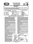
SAFETY
Instructions are necessary before operating or servicing machine. Read Operation &
Maintenance Manual, Handbook and signs (decals) on machine. Fo'1lowwarnings and
instructions in the manuals when making repairs, adjustments or servicing. Check for
correct function after adjustments, repairs or service. Failure to follow instructions can
. cause injury or death.
W-2003-1089
Safety Alert Symbol:
This symbol is used for important safety messages. When you see this symbol. follow the safety
message to avoid personal injury or death.
CORRECT
w
8-10731
A Never service
the Bobcat loader
without instructions.
8-12365
A Don't
lift or lower operator cab
without instruction.
8-7469
A Cleaning and maintenance are
required daily.
A Keep rear doo: closed except for
service. Close and latch door before
operating the loader.
WRONG
WRONG
8-11799
A Have
good ventilation
when
welding or grinding painted parts.
Wear dust mask when grinding
painted parts. Toxic dust and gas
can be produced.
WRONG
8·3724
A Vent
exhaust to outside when
h engine must be run for service.
~ Exhaust system must be tightly
sealed. Exhaust fumes can kill
without warning.
8-6593
A Never work on loader with lift arms
A
up unless lift arms are held by a lift
arm support device.
Never modify equipment or add
attachments
not approved by
Melroe Company.
WRONG
WRONG
8-6590
A Stop,
cool and clean engine of
flammable
materials
before
checking fluids.
Never service or adjust loader with
the
engine
running
unless
h instructed to do so in the manual.
~Avoid
contact
with
leaking
hydraulic fluids or diesel fuel which
is under pressure. It can penetrate
the skin or eyes.
Never fill fuel tank with engine
running, while smoking or when
near open flame.
A
A
8-6589
Keep body, jewelry and clothing
away from moving parts, electrical
h contacts, hot parts and exhaust.
~ Wear eye protection to guard from
battery acid, compressed springs,
fluids under pressure and flying
debris when engines are running or
tools are used. Use eye protection
approved for type of welding.
A Lead-acid
batteries
produce
h flammable and explosive gases.
~
Keep arcs, sparks, flames and
lighted
tobacco
away from
batteries.
Batteries contain acid which burns
eyes or skin on contact. Wear
protective clothing. If acid contacts
body, flush well with water. For eye
contact
flush
well and get
immediate medical attention.
A
10-91
INTRODUCTION
Melroe recommends that all service
Workshops for necessary information
technicians attend
and education.
either field
or factory
Bobcat
Service
Workshops are held many times a year at various locations throughout the U.S. and Canada. Contact
your District Service Manager or Melroe Service Office Gwinner, N.D. (7011678-6465
for schedule.
This Component Repair Manual provides the Service Technician with information
Hydraulic Cylinders.
Refer to the SERVICE MANUAL
the hydraulic cylinders.
for your MODEL Loader to troubleshoot,
for servicing Melroe
test, remove and install
SAFETY INSTRUCTIONS
We Care About your Safety.
Wear safety glasses to prevent eye injury
when any of the following conditions
exist:
• When fluids are under pressure.
• Flying debris or loose material is
present.
• Engine is running.
• Tools are being used.
W-2019-1285
BEFORE YOU WORK ON THE HYDRAULIC CYLINDER
Read the complete sequence so you know the complete disassembly
is actually started.
AWARNING
Warnings
on the machine
and in
or assembly procedure before the work
IMPORTANT
This notice identifies
procedures
the manuals are for you, safety.
which must be followed
Failure to obey warnings can
damage to the loader.
to avoid
cause injury or death.
W-2044-1285
1-2019-0284
Hydraulic Cylinder
Component Repair Manual
1
HYDRAULIC
CYLINDER
CYLINDER IDENTIFICATION
Tilt Cylinder
Components
on 753 & 853
7
Tilt Cylinder
Components
on 753 & 853
8
Tilt Cylinder
Components
640 & 740 Series
(Equipped
with
Tilt Cylinder
& 843
Cushion
Components
(* Not Equipped
Sleeve) ..................•....
on 540, 640,
*740
with
Sleevel
Cushion
6
Series
5
Tilt Cylinder
Components
on farm boy, 440, 443
4
Lift Cylinder
Components
on All 40 Series
3
HYDRAULIC
CYLINDER
Assem bly . . . . . . . . . . .
Cylinders
With Cushioned
Cylinders
Without
.
Piston
Cushioned
Piston
Disassembly
HYDRAULIC
11
14
15
9
CYLINDER SERVICE TOOLS
MEL-1032
or MEL-1033
MEL-1075
Adjustable
Rod Seal Tool
Gland Nut Wrench
MEL-1178 Seal Tool
1
1
2
MEL-1076
Cylinder
MEL-1074
O-ring Seal Hook
Wrench .....................•..•...
2
1
MEL-1396
Seal Tool
1
TORQUE SPECIFICATIONS
Aluminum
Piston
.............................•....
Gray Iron Piston ....................•..............
17
17
Hydraulic Cylinder
Component Repair Ma'lual
HYDRAULIC
CYLINDER SERVICE TOOLS
A
MEL-1074 O-Ring Seal Hook
Use this tool to remove the seals from the piston and the cylinder
head
I!J.
8-7211
MEl-1396 Seal Installation
Tool
B
Use this tool to stretch the Teflon seals before installing
on cylinder pistons [!J.
seals
Use ring compressor to compress the Teflon seal into the groove
after installing it on the piston.
8-12810
MEL-1032 or MEL-1033
Rod Seal Installation
Use one of these tools to install internal
c
Tool
seals in the cylinder
head. Use Tool UMEL-1033 when servicing cylinders with rods
1-1/4"
in diameter through
2" diameter
[g.
8-7213
MEL-1075
Adjustable
Gland Nut Wrench
D
Use this tool with correct pins (Tool #MEL-l075-1
or
MEL-1075-21 for the cylinder head removal and installation ~.
I
B-7 112
-1-
Hydraulic Cylirider
Component Repair Manual
I
HYDRAULIC
MEl-1076
CYLINDER SERVICE TOOLS ICont'dl
A
Cylinder Wrench
Use this tool to remove the end cap from the hydraulic cylinder
I!J.
6-12677
Hydraulic
-2-
Component
Cylinder
Repair Manual
CYLINDER IDENTIFICATION
Lift Cylinder Components
on All 40 Series
1. Rod
2. Case
3. Nut
4. Piston
5. Piston Seal
6. O-Ring
7. Spacer
8. O-Ring
9. Back-Up Washer
10. Head
11. Rod Seal
12. Wiper Seal
6
4
i /
I ~/
·3
I /
/
~
if
/
• See Page 17 for torque.
Hydraulic Cylinder
-3-
Component Repair Man~al
CYLINDER IDENTIFICATION
{Cont'dl
Tilt Cylinder Components on farmboy, 440. 443
1.
2.
3.
4.
5.
Rod
Case
Nut
Piston
O-Ring
Piston Seal
7. O-Ring
8. Back-Up Washer
9. End Cap
10. Head
11. Wiper Seal
6.
/"
,/ q-l0
,
<
\
\
Q-11
\
/
/\ \
\
/
/
(/
\
,
\
\
\
\
\
\,
\
,,
,
\
\
\
\
\
\
\
\
\
\
\
\
\
\,
\,, 1-0
'\
\ B-O
\
\
\
\
\
*3-
,
0
\
'\
4-.
\
\
\
'\
\
,
/
\
&-Q
////
\
\
\
\
\
,,
\
\
\
\
/'
\
,/
\
\
'
/
/
\
///
\
/
\
/
\/
/
\
/
\
*
\
\
\
5-0
\
\
\
\
\
\
\
\
\
\
\
\
\
\
\'
\
\
\
\
\
\~
,\
\
v
/
See Page 17 for torque.
-4-
C·2808
Hydraulic Cylinder
Component Repair Manual
CYLINDER IDENTIFICATION
r---..
(Cont'd)
Tilt Cylinder Components on 540. 640. 740* Series & 843
1* Not Equipped With Cushion Sleeve)
1,
2.
3.
4.
5.
6.
7.
8.
9_
10.
11.
Rod
Case
Nut
Piston
O-Ring
Piston Seal
O-Ring
Back-Up Washer
End Cap
Head
Wiper Seal
/'"
\
/
/
,,
0-10
\
\
<
\
\
11
0\
\
\
\
\
\
\
\
\
\
\
\
\
\
*3-®
\
\
\
\
\
\
\
\
\
4-(t)
\
)
/
/
\
/
/
/
/
\
/
\
/
y/
* See Page 17 for torque.
C-2808
Hydraulic
-5-
Cylindet-
Component Repair Manua~
CYLINDER IDENTIFICATION (Cont'd)
Tilt Cylinder Components on 640* & 740*
(* Equipped With Cushion Sleeve)
Series
1. Rod
2. Case
3. Nut
4. Piston
5. D-Ring
6. Piston Seal
7. Cushion Sleeve
S. D-Ring
9. Sack-Up Washer
10. End Cap
11. Rod Seal
12. Wiper Seal
//'0-11
\
/
\
/
(
"fa
//f-€;
q-12
\
\
\
"\
(\
\
\
\
\
\ 5-Q
\
\
\
\
\
\,
\,
\ 6-0
\
\
\
\
\
\
\
\
\
.3-®,
\
\
\
\ 8-0
\'\ 9-0
5-\0
\>
,,\
\
\
/
/
.:
'\
10-. /////
\
\
6-0
\
\
\
\
\
\
\
\
\
\
\
\
\
\
\
\
\
\
)
/
/
'v//
/
\
\
/
/
\
V
* See Page l' for torque.
-6-
C-2742
Hydraulic Cylinder
Component Repair Manual
CYLINDER IDENTIFICATION (Cont'd)
Tilt Cylinder Components on 753 & 853
1.
6.
Case
Tube
Plug
O-ring
Bolt
Clamp
7.
Nut
8.
Piston
Seal
2.
3.
4.
5.
9.
10.
O-ring
11. O-ring
12. Washer
13. O-ring
14. Head
15. Seal
16. Seal
17. Rod
19. Bushing
J I
Me-1688
-1
~
-------
~\~.
. .
r *5--0.
---
6-~
__
@-7
-\
."
L.
,--
-0-
•
··
·
_011
\
4 \
~
3
-,
•
··•
.
·•.
•,
..,
.,.
,
0.
10
0,
..
.
•
0,
,
0-16
.,
..
..
G
·,
•
0-
12
,
(J-13
·..,
17- ~
.,,
.,
\ 18-0
..,
~
,,
--~
MC-1B88
!t.-lbs. (543-577
,,
..,
..
,
,
,
11
Tighten To 400-425
~-i5
•
\
*
..,
,,
9
I
..
.
~-14
,
,
,
Nm) Torque.
TS-l01
Hydraulic Cylinder
-7-
Component Repair Manufl
CYLINDER IDENTIFICATION ICcntdl
Tilt Cylinder Components on 753 & 853
1.
2.
3.
4.
5.
6.
7.
Case
Tube
Plug
O-ring
Nut
Clamp
Nut
8. Piston
9. Seal
10.
11.
12.
13.
14.
15.
16.
17.
18.
O-ring
O-ring
Washer
Q-ring
Head
Seal
Seal
Rod
Bushing
~
Me-16BB
--~~,"
~\
\
\
--0--'1-3
\ ;S-@ I
6-tiI
,
\
\ 4
\
7-®
\
\
\
\
®-8
\
\
\
\
\
\
\
\
\
\
9
0,
©-15
\
\
\
,
\
\
0-10
0-16
\
\
,
\
0-
\
11
\
\
00-
\
\
12
\
\
\
13
,
\
\18-0_
I
\
---I
*
Tighten To 425-525
ft.-Ibs. !576-712
Nml Torque.
TS-,063
-8-
Hydraulic Cylinder
Component
Repair Manual
HYDRAULIC
CYLINDER
A
Disassembly
r'
NOTE:
The drawings
may not show
the cylinder
exactly
as
it appears. but the procedure is correct for all cylinders.
See the Service Manual for your model loader to find the correct
information for removing and installing the cylinder.
cylinder in a drain pan. Move
the rod in and out to remove the fluid from the cylinder. Move
the rod slowly so the fluid will go directly into the drain pan.
Put the base end of the hydraulic
Put the base end of the cylinder
in a vise.
8-7000
Use the adjustable
gland nut wrench
to loosen the
hea1d ~.
B
Remove the rod assernblv from the cylinder case
lID.
Remove the cylinder case from the vise.
Put the rod end in the vise.
8-7001
c
Remove the nut from the piston end of the rod ~.
Pull the piston off the rod litem I} ~.
D
If the cylinder has a cushion sleeve (Item 2), pull it off the rod
~.
Pull the head litem 3} off the rod ~.
8-7003
-9-
II
Hydraulic Cylinder '
Component Repair Manual
HYDRAULIC CYLINDER ICont'dl
If the head has a seal, remove
A
the seal from the head
~.
B-7004
Remove
the O-ring
and back-up
washer
from
the head
[ID.
8-7199
Remove
the wiper
seal ~.
8-7005
Remove the oil seal from the head
[QJ.
9-7006
-10-
Hydraulic Cylinder
Component Repair Manual
HYDRAULIC CYLINDER (Cont'd)
A
Remove the piston seal from the piston ~.
I,
8·3689
Remove the O-ring from the piston
Wash the cylinder
I!l.
B
parts in solvent and air dry them.
While servicing the cylinder do not damage the parts. Inspect
for nicks, scratches or otherwise damaged or bent parts before
assembling the cylinder. Replace parts that appear damaged in
any way. The cylinder may not function correctly if there is
damage to any of the parts.
Destroy all.the O-rings and seals and replace them with NEW
O-rings and seals.
8-3703
c
Assembly
Install the D-ring on the piston ~.
B-12812
NOTE:
Do not overstretch the seal.
D
Install the seal on the tool and stretch it until it fits the piston
~.
Allow the D-ring to stretch for 30 seconds before removing it
from the tool.
8-12809
Hydraulic
-11-
Component
Cylinder
Repair Manual I
HYDRAULIC
CYLINDER ICont'd)
A
Install the seal on the piston [!].
8·12813
Use the ring compressor
size
lID.
to compress
the seal to the correct
B
Leave the piston in the ring compressor for three minutes.
s-:
8-12811
Install the oil seal on the rod seal tool
©.
NOTE: The O-ring side of the oil seal goes toward
c
the inside
of the cylinder.
-:
./
Install the oil seal in the head ~.
//
/
8·3702
D
-12·
Hydraulic Cylinder
Component Repair Manual
HYDRAULIC CYLINDER (Cont'd)
A
Install the wiper seal with the lip toward the outside of the head
~~
Install the back-up washer on the head
lID[9.
B
8-7008
Install the O-ring next to the back-up ring
[Q].
D
8-7007
-13-
Hydraulic Cylinder
Component Repair Manua~
I
HYDRAULIC
CYLINDER (Cont'd)
A
If a seal was removed from the head use the following procedure
to install a new one.
1. Install the guide (with a pilot and an adapter if they are
required (See Special Tools Page 1) on the head.
2. Install the seal on the head using the guide [!].
NOTE:
Do not turn Iroll) the seal as you install it. Damage
to the seal may result.
B·7009
3. Use a ring compressor to compress the seal to the correct
size
[iJ. Leave the
B
tool over the Teflon seal for five minutes.
8-7010
Install the head on the rod
19.
c
,
8-7011
Cylinders With Cushioned
Piston:
Install the piston on the rod with the tapered end first (toward
the head) @.
-14-
Hydraulic Cylinder
Component Repair Manual
r">.
HYDRAULIC CYLINDER ICont'd)
r>.Cylinders
Without Cushioned Piston:
Install the cushion sleeve and the piston on the rod ~.
B-3B53
Lubricate the threads and install the nut
lID.
B
See Page 15 for the correct torque specifications.
Remove the rod from the vise.
Install the cylinder case in the vise.
B-7002
Put oil on the seal surface of the cylinder case
[g.
c
8-7013
Put oil on the Teflon seal on the piston ~.
8-7012
-15-
Hydraulic Cylinder
Component
Repair Manual
HYDRAULIC
CYLINDER ICont'd}
Install the rod assembly
A
in the cylinder case ~.
8-7001
Put oil on the seals on the head
Put oil on the threads
[ID.
B
of the head.
LUse the adjustable
gland nut wrench
to tighten
the head
[9.
8-7014
~~
c
8-7000
Replace the seal on the rod end (if so equipped) if it shows signs
of wear or damage [Q].
8-7015
-16-
Hydraulic Cylinder
Repair Manual-
Component
TORQUE SPECIFICATIONS
NOTES
_
All torques shown are for lubricated threads.
r--...
Aluminum
Piston
Boom Cylinder
(Trencher)
3/4" Thread
.
7/8" Thread ..
1" ............•...
1· 1/8"' Thread .....••........•......
Gray Iron Piston
7/8" Thread . . . .
1· 1/8" Thread
, . • . ..
1·1/4" Thread ...............•.......
1· 1/2" Thread
2" Thread ......•.........••.........
. ..•.......
.
.
.
Ft.·Lbs.
Nm
100· ",
150·160
170·210
330·360
330·360
135·150
205·217
230·285
447-488
447-488
250·300
470·550
700·800
800·900
1800·2200
·17·
340-407
637·746
949· 1085
1085·1220
2440·2983
Hydraulic Cylinder
Component Repair Manual
NOTES
NOTES