1
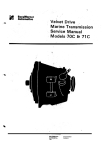
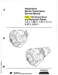
SERVICE M A N U A L
n
A'
HYDRAULIC TRANSMISSION
REDUCTION GEAR ASSEMBLY
h
2.100 :1 RATIO
WARNER GEAR
Muncie, Indiana
n
P R I C E $1.50
C4
DIVISION OF BORG WARNER CORPORATION
SERVICE MANUAL
HYDUllUlIC TRANSMISSION
REDUCTION GEAR ASSEMBLY
2.100:l RATIO
S e r v i c e Manual S u p p l e m e n t for 2.100 t o 1 R e d u c t i o n U n i t s , for
e i t h e r right hand o r left hand r o t a t i o n units. T h i s manual
t o be used in c o n j u n c t i o n with m o d e l s 70, 71 and 72 S e r v i c e
M a n u a l s w h i c h will have slight v a r i a t i o n s as noted in t h i s
supplement.
WARNER GEAR
marine
transmissions
Muncie, Indiana
DIVISION OF BORG WARNER CORPORATION
TABLE OF CONTENTS
CROSS SECTION ASSEMBLY DRAWINGS . . . . . . . . . . . . . . . . . . . . . . . . . . . . . . . . . . . . . . . . 3
PARTS DISPLAY AND INFORMATION ............................................... 5
DESCRIPTION ............................................................. 8
DISASSEMBLY OF TRANSMISSION ................................................ 9
Removal o f reduction housing. ring
gear and main shaft assembly
Removal of pinion cage
.............................................. 9
a s s e m b l y ........................................ 9
Removal of reduction unit adapter and
sun gear assembly
......................................................
9
Disassembly of ring gear. main shaft.
coupling and bearing from reduction
housing
.............................................................. 9
Disassembly of Forward & Reverse
Transmission
.......................................................... 9
INSPECTION AND GENERAL INSTRUCTIONS .......................................... 10
ASSEMBLY OF TRANSMISSION ................................................... 10
Assembly of pinion cage & output
shaft in the transmission case
....................................... 10
Selection of proper thrust washer for
satisfactory end clearance
...............................................11
Assembly of s u n gear and reduction
unit adapter o n forward & reverse
transmission case
..................................................... 1 2
Assembly of pinion cage assembly to
transmission
..........................................................12
Assembly of bearing into the reduction housing
.......................................................... -13
Assembly of main shaft assembly.
bearing retainer. coupling and main
shaft nut in reduction housing
.......................................14
Assembly of reduction housing. ring
gear and main shaft assembly to the
forward and reverse transmission
.......................................15
BoLT TORQUE SPECIFICATIONS. ................................................. 16
GENERAL INFORMATION ....................................................... 16
I
I6
Fig. I
:
I
Cross Section o f AS3-70C Transmission
Ii
1
I
Fig. 2
Cross Section o f AS3-71C Transmission
3
i
I
Fig. 3
Fig. 4
Cross S e c t i o n o f AS13-72C Transmission
Rear View o f Model 70C & 71C Transmissions
Fig. 5
Rear View o f Model 72C Transmission
Br
Fig. 6
L
L
INDEX
NO. PART NO.
I
2
3
4
5
71-IH
4636EZ
71-140
71 -A98
120428
P a r t s D i s p l a y f o r Forward & Reverse a e c t l o n o f t h e AS3-luc ~ r a n s m i s s i o n .
Only Those P a r t s D i f f e r e n t from the ASI-70C Assembly I1l u s t r a t e d . .
PART NAME
TRANSMISSION CASE
NAME PLATE
BAFFLE
OIL STRAINER ASSEMBLY
ANNULAR GASKET
l",",'","
PART NO.
6
7
8
9
10
453006
71-158
or
71-15C
71 -159
71-IA2B
I
I
I
l
1
NO.
REOfD
PART NAME
OIL DRAIN PLUG
I
SELECTIVE THRUST WASHER
I
THRUST WASHER
I
PlNlONCAGEd(0UTPUTSHAFTASS'Y. I
.
Fig. 7
I 'cEX]
PART NO. I
P a r t s D i s p l a y f o r Forward & Reverse S e c t i o n o f t h e AS3-71C Transmission.
Only Those P a r t s D ~ f f e r e n tfrom t h e ASI-71C Assembly a r e I l l u s t r a t e d .
PART NAEE
TRANSM ISS I ON C A S E
NAME PLATE
BAFFLE
O I L STRA lNER ASSEMBLY
ANNULAR GASKET
OIL D R A I N PLUG
I ~ I~ - ~ ~ ~
71 5 C ~ rSELECT l VE THRUST WASHER
NDEX
REQ'D I NO.
1
I
11
1
I
I
I
1
1
9
10
11
12
13
PART NO.
/
71 - 159
71 -IA2B
R6-177
72-A66B
72-176
NO.
REO'D
PART NAME
I
I
THRUST WASHER
PINION CAGE & OUTPUT SHAFTASS'Y.
DOWELPIN
REVERSE CLUTCH PLATE
OUTER CLUTCH PLATE
I
I
3
2
I
Fig. 8
INDEX
NO.
1
2
3
4
5
6
6
PART
NO.
72-1 K
4636FU
71 -A98
453006
71-1 59
72-lA28
P a r t s D i s p l a y f o r Forward & Reverse S e c t i o n o f t h e AS13-72C T r a n s m i s s i o n .
Only Those P a r t s D ~ f f e r e n tf r o m t h e AS1 I- 72C Assembly a r e I l l u s t r a t e d .
NO.
I N D E ~ P A RT
NO.
REQ'D NO.
TRANSMISSION CASE
71-158
1
7
or
NAME PLATE
I
71-15C
8
O I L STRAINER ASSEMBLY
I
46228
9
O I L DRAIN PLUG
I
10 72-A66B
THRUST WASHER
I
ll
72-1 76
PlNlONCAGE&OUTPUTSHAFT
I
PART NI\ME
PART NAME
NO.
REQ'D
SELECTIVE THRUST WASHER
I
DOWEL PIN
REVERSE CLUTCH PLATE
OUTER CLUTCH PLATE
3
3
2
Fig. 9
INDOEX
PART NO.
1
2
4775L
4547BA
3
4
4547AY
3-62
1 79860
5
6
7
8
9
10
1 03322
L4-7
L4-147
X3372
L5-I
L4-146
I1
4853
lzEX
PART NAME
OUTPUT SHAFT NUT
COUPLING FOR 70 h 71
MODELS
COULING FOR 72 MODEL
OIL SEAL
7 1 6-1 4x1 -1 14 HEX HEAD
B LT
711 6 LOCKWASHER
BEARING RETAINER
BEARING RETAINER GASKET
BEARING
REDUCTl ON HOUS l NG
REDUCCTlON HOUS l NG GASKETREAR
LOCK BOLT
6
P a r t s v l s p l a y f o r 2.100 t o I
PART NO.
I
1
6
I
I
1
6
12
13
14
15
16
17
18
,
g
20
21
22
eduction b n l t
d
PART NAME
1 1 4607
L5-A2
L3-6
4756D
L3-24
L5-IAI 50
7116 LOCKWASHER
MAIN SHAFT
R l NG GEAR
R ING GEAR SNAP RING
THRUST WASHER
PLANETARY ASSEMBLY FOR
AUTOMOTl VE ROTATl ON
L5A-I A 1 50 PLANETARY ASSEMBLY FOR NON
AUTOMOTl VE ROTATl ON
L5-4
SUN GEAR
L5-8
REDUCTION UN IT ADAPTER
476a
SNAP RING
L4-145
REDUCTION UNIT ADAPTER
GASKET-FRONT
-- - --- - S
6
I
1
I
I
I
PART NO.
23
179864
24 103322
PART NAK
7116-14x1-314 HEX HEAD
BOLT
711 6 LOCKWASHER
NO.
2
2
DESCRIPTION
T h e 2.100 t o 1 r e d u c t i o n g e a r box
operates i n c o n j u n c t i o n w i t h any o f
the following models: Model 70, 70R,
7 0 C , 70CR, 7 1 , 7 1 R , 7 1 C , 71CR, 7 2 ,
72R, 72C, and 72CR.
T h e reduction gear box consists o f a
planetary gear set which is always
engaged and reduces the input revolut i o n b y a 2.100 t o 1 ratio.
The
splined output shaft of the reduction
g e a r b o x is c o a x i a l w i t h t h e i n p u t
shaft o f the m a i n unit and w i t h the
transmission operating in forward its
direction o f rotation is the same as
that o f t h e e n g i n e rotation.
Lubricating oil is supplied b y the pump
i n the main t r a n s m i s s i o n and is
returned to the main transmission by
gravity and jet flow.
Location of several transmission
details are shown in (Figures 10 and
11). as follows:
A. Oil Filler Plug
Oil outlet Opening to Cooler
C. Oil Inlet Opening from Cooler
D. Mountings Pads and Mounting Bolt Holes
E. Shift Lever
F. Oil Drain Cap
G. Breather
H. Drive Gear
I. Valve Cover
J. Coupling
K. Oi l Pump
L. Reduction Gear Box
B.
c
,F
CAUTION
NOT1:: Either item 17 or 18 on the preceding page is used depending upon
the transmission rotation. As can be seen 1;y checking the two parts in
". ure 9 t h e pinion placement is different for the two assemblies.
DO NOT USE T H E WRONG ASSEMBLY
Fig. 10 Left SLde o f Transmission
Fig. I I
Right Side, o f Transmission
m
DISASSEMBLY OF TRANSMISSION
REMOVAL O F REDUCTION HOUSING,
GEAR AND MAIN SHAFT ASSEMBLY
RING
8.
P l a c e t r a n s m i s s i o n r i g h t s i d e up on
a c l e a n bench and loosen t h e main
s h a f t nut.
Remove s n a p r i n g f r o m s u n g e a r , t h e n
remove s u n g e a r from r e d u c t i o n u n i t
adapter.
DISASSEMBLY O F R I N G GEAR, M A I N
SHAFT, COUPLING AND BEARING FROM
REDUCTION HOUSING
Place an inch t h i c k block under the
r e a r of forward and reverse transmission j u s t forward of reduction
unit adapter s o that reduction unit
w i l l c l e a r bench.
9.
Remove m a i n s h a f t n u t a n d c o u p l i n g
and s l i d e r i n g g e a r and main s h a f t
from r e d u c t i o n housing.
1 0 . Remove s n a p r i n g a n d m a i n s h a f t f r o m
A transmission stand similar
NOTE:
t o t h e o n e s h o w n i n ( F i g . 1 2 ) may b e
b u i l t from one i n c h a n g l e i r o n .
One
p i e c e is placed t o hold t h e t r a n s m i s s i o n from s l i d i n g forward and a
second angle is placed t o support
t h e case j u s t forward of the reduction unit adapter.
The two a n g l e s
may b e w e l d e d t o a n y s u i t a b l e s u p porting pieces.
Remove t h e t w o 7 / 1 6 b o l t s a n d l o c k washers which f a s t e n t h e r e d u c t i o n
housing and t h e reduction adapter t o
t h e forward and r e v e r s e t r a n s m i s s i o n
c a s e , a n d t h e 3/8 b o l t s w h i c h f a s t e n
the reduction adapter t o the reduct i o n housing.
Slide the reduction
housing, r i n g g e a r and main s h a f t
assembly rearward off the transmission.
REMOVAL O F P I N I O N CAGE ASSEMBLY
ring gear.
1.1. Remove b e a r i n g r e t a i n e r a f t e r r e m o v i n g s i x hex head b o l t s and lockwashers t h a t r e t a i n it.
12. L i f t r e a r b e a r i n g cone from i t s cup.
13. T h e o u t e r r a c e a n d f r o n t c o n e c a n
b e p r e s s e d from r e d u c t i o n h o u s i n g on
an arbor press.
P r e s s on r e a r f a c e
of f r o n t bearing cone while reduct i o n housing is supported on its
r e a r f a c e on a c l e a n f l a t s u r f a c e .
DISASSEMBLY O F FORWARD & REVERSE
TRANSMISSION
14.
Follow disassembly procedures given
i n S e r v i c e Manual 'Velvet D r i v e '
H y d r a u l i c T r a n s m i s s i o n e i t h e r Model
70, 71, o r 72 a s required f o r d i s assembly of forward and reverse
transmission.
Remove t h r u s t w a s h e r f r o m r e a r o f
planet cage.
S l i d e planet cage assembly rearward
from u n i t .
Remove t h r u s t w a s h e r from r e a r o f
sun gear.
REMOVAL OF REDUCTION U N I T ADAPTER
AND SUN GEAR ASSEMBLY
Remove s i x l o c k b o l t s a n d l o c k washers t h a t r e t a i n reduction u n i t
a d a p t e r , t h e n remove a d a p t e r a n d s u n
g e a r assembly from forward and r e verse transmission.
Fig.
12
T r a n s m i s s i o n on s t a n d
INSPECTION AND GENERAL INSTRUCTIONS
1.
Cleanliness is absolutely necessary
during assembly t o insure proper
functioning of transmission. Transmission c a s e passages should always
have p l u g s removed t o a l l o w f o r
thorough c l e a n i n g .
When a v a i l a b l e
use compressed a i r t o d r y p a r t s before they a r e assembled.
Do n o t
wipe p a r t s w i t h r a g s t o c l e a n o r d r y
t h e m a s l i n t f r o m t h e c l o t h may
cause e r r a t i c valve action.
2.
I n s p e c t a l l p a r t s f o r damage o r
wear.
Replace defective parts.
3.
A l l g a s k e t s , o i l s e a l s and r u b b e r
sealing r i n g s should be replaced
e x c e p t i n r e l a t i v e l y new u n i t s .
Judgement s h o u l d t h e n be e x e r c i s e d
a s t o t h e need f o r r e p l a c i n g t h e s e
parts.
4.
O i l s e a l s and b e a r i n g s a r e b e s t i n s t a l l e d by u s i n g an a r b o r p r e s s ,
s u i t a b l e f i x t u r e s , and t o o l s t o
p r o p e r l y a l i g n p a r t s being assembled.
Hammering s e a l s and b e a r i n g s
i n t o p o s i t i o n c a n s e v e r l y damage
parts.
5. Automatic transmission f l u i d type
'A' s u f f i x 'A' should be used t o
l u b r i c a t e p a r t s a s t h e y a r e assembled.
P e t r o l e u m j e l l y may b e u s e d on
g a s k e t s o r o t h e r p a r t s t h a t must b e
held i n p o s i t i o n during assembly.
A l l r u b b e r p a r t s w i l l s l i d e moreL
freely i f lubricated.
6.
T i g h t e n a l l b o l t s a n d s c r e w s e v e n l 1.
t o t h e recommended t o r q u e . ( s e e page
16).
7. A l l p i n i o n cage s e r v i c e i n s t r u c t i o n s
a r e c o v e r e d i n t h e S e r v i c e Manual
'Velvet Drive' Hydraulic Transm i s s i o n u n d e r P i n i o n Cage S e r v i c e
Instruction sheets.
ASSEMBLY OF TRANSMISSION
ASSEMBLY OF PINION CAGE & OUTPUT
SHAFT I N THE TRANSMISSION CASE
i t i o n e d i n c a s e g r o o v e a s shown i n '
(Fig. 1 3 ) .
1
d
P l a c e t h e r e d u c t i o n housing on i t s
forward f a c e , and then s e t t h e
transmission case s o t h a t i t s r e a r
f a c e i s s u p p o r t e d on t h e r e a r f a c e
of t h e reduction housing.
This
w i l l provide proper support f o r the
t r a n s m i s s i o n c a s e d u r i n g t h e assemb l y o f t h e forward and r e v e r s e u n i t
when t h e p i n i o n c a g e a n d o u t p u t
s h a f t assembly p r o t r u d e s from t h e
r e a r of t h e case.
2.
Coat s t e e l back of t h r u s t washer
with petroleum jelly.
Install
t h r u s t w a s h e r on i n s i d e t h r u s t s u r f a c e of c a s e w i t h washer t a n g pos-
3 . I n s t a l l p i n i o n c a g e and o u t p u t s h a f t
f l u s h a g a i n s t t h r u s t w a s h e r a s shown
i n (Fig. 14).
Avoid r o t a t i o n o f
p i n i o n c a g e and o u t p u t s h a f t d u r i n g
assembly a s it tends t o unseat
washer t a n g from i t s g r o o v e .
NOTE: P i n i o n c a g e a n d o u t p u t s h a f t
a s s e m b l y ( 7 2 - 1 A 2 B ) i s now b e i n g
supplied with three o i l grooves
around t h e l a r g e s h a f t diameter a s
shown i n ( F i g . 1 5 ) . T h i s new s h a f t
can be used t o replace e a r l i e r
shafts.
However t h e e a r l i e r s h a f t s
w i t h o u t t h e g r o o v e s must n o t b e u s e
w i t h t h e l a t e s t f o r w a r d and r e v e r s e .
9
transmission cases supplied without
71-28R b u s h i n g s .
4.
Complete forward and r e v e r s e t r a n s mission assembly by following
instruct.ions given i n e i t h e r Service
Manual f o r Model 7 0 , 7 1 , o r 7 2
'Velvet D r i v e V y d r a u l i c Transmission a s required.
SELECTION OF PROPER THRUST WASHER
FOR SATISFACTORY END CLEARANCE
5.
6.
Forward and r e v e r s e u n i t end c l e a r ance should b e checked by p l a c i n g
a n i n d i c a t o r on e i t h e r i n p u t s h a f t
o r o u t p u t s h a f t a s shown i n ( F i g .
16).
Shove a l l p a r t s t o f r o n t o f
c a s e , s e t i n d i c a t o r on z e r o , and
t h e n move a l l p a r t s t o r e a r o f c a s e
by pushing on d r i v e g e a r .
End
c l e a r a n c e should read between .004
and .043 i n c h .
Fig.
14
I n s t a l l i n g P i n i o n Cage and
Output Shaft
W SHAFT
/'
Replace s e l e c t i v e t h r u s t washer i f
necessary t o b r i n g end play within
above l i m i t s .
NOTE:
End p l a y c h e c k e d d u r i n g d i s assembly permits selection of
c o r r e c t washer during reassembly.
.. ,
Fig.
Fig.
13
T h r u s t Washer w i t h Tang and
Groove A l i gned
15
Fig.
L a t e and E a r l y Model P i n i o n
Cage and O u t p u t S h a f t s
16
C h e c k i n g End P l a y
9.
S l i d e sun g e a r s p l i n e s i n t o reduction unit adapter splines until gear
b o t t o m s on s h o u l d e r o f a d a p t e r .
10. S u p p o r t r e d u c t i o n u n i t a d a p t e r and
s u n g e a r on r e a r f a c e o f s u n g e a r
and i n s t a l l snap r i n g f i r m l y i n t o
i t s g r o o v e a s shown i n ( F i g . 1 8 ) .
11. I n s t a l l a d a p t e r a n d s u n g e a r o v e r
t h e t r a n s m i s s i o n o u t p u t s h a f t and
locate p i l o t of adapter into bore
provided i n r e a r of transmission
case.
12.
A s s e m b l e t h e two 7 / 1 6 - 1 4 X 1 - 3 / 4 h e x
head b o l t s t o i n s u r e c o r r e c t a l i g n ment, b u t do not t i g h t e n .
13.
I n s t a l l s i x NEW 7 / 1 6 - 1 4 X 1 n y l o c k
b o l t s and e x t e r n a l t o o t h l o c k w a s h e r s
Tighten bolts
shown i n ( F i g . 1 9 ) .
e v e n l y a n d t o r q u e t o 4 2 - 5 0 poundsfeet.
l KANSM l SS l ON
Fig. 17
ction Unit
, .
I n s t a l 1 i n,~ gRedu
naaprer G a s ~ e r - F r o n t
. > - _ l .
ASSEMBLY OF SUN GEAR AND REDUCTION
UNIT ADAPTER ON FORWARD & REVERSE
TRANSMISSION CASE.
7.
8.
Support Forward and Reverse t r a n s m i s s i o n on i t s f r o n t f a c e o r p l a c e
i t upright on bench with an inch
block under back of t r a n s m i s s i o n t o
g i v e c l e a r a n c e needed f o r assembling
A transreduction unit parts.
m i s s i o n s t a n d may a l s o b e u s e d a s
described i n the disassembly section
of t h i s manual.
Coat r e a r f a c e of c a s e w i t h p e t r o l eum j e l l y a n d i n s t a l l r e d u c t i o n u n i t
a d a p t e r g a s k e t - f r o n t on r e a r f a c e
o f t r a n s m i s s i o n c a s e a s shown i n
(Fig. 17).
-
1 4 . Remove t h e t w o 7 / 1 6 - 1 4 X 1 - 3 / 4 h e x
head b o l t s , which were i n s t a l l e d
i n s t e p (6).
AZSEMBLY OF PINION CAGE ASSEMBLY TO
TRANSMISSION
15. I n s t a l l t h e t h r u s t w a s h e r o n h u b o f
s u n g e a r a s shown i n (Fig. 20).
16. E n g a g e p i n i o n g e a r s w i t h s u n g e a r
t e e t h a s planet cage assembly is
slowly rotated t o align pinion cage
splines with output shaft splines,
then bottom cage against t h r u s t
washer on r e a r of sun gear.
SNAP
RING
REDUCT l ON UNIT
ADAPTER
Fig. 18
I n s t a l l i n g Sun Gear Snap Ring
Fig. 19
1
Removing t h e Two 7 16 I n c h Bolts
After T ~ g h t e n i n gt e 6 Nylock Bolts
,
I
CAUTION:
T w o p l a n e t a r y c a g e and
pinion sub-assemblies are available
for the 2 . 1 0 0 -1 ratio reduction
units.
Selection o f proper s u b assembly is dictated by direction of
transmission rotation. Part numbers
and matching direction o f rotation
are shown in (Fig. 9 ) . Correct cage
assembly must be used at all times.
The pinions are located differently
in the two assemblies.
Install thrust washer on the hub of
pinion c a g e as s h o w n in (Fig.21).
THRUST ~ I AUSF RI , ~ ,P~ I,N'I
,1 O N CAGE
ASSEMBLY OF RING GEAR TO MAIN SHAFT
F i g . 21
18. Install mainshaft into r i n g gear.
b
REDUCTION UNIT MAIN
SHAFT ASSEMBLY
19. Assemble snap ring firmly into ring
gear groove as shown in
(Fig.
I n s t a l l i n g P i n i o n Cage T h r u s t
Washer
22).
I4-4
20. A s s e m b l e r i n g g e a r and m a i n s h a f t
over pinion carrier rotating the
ring gear to properly align gear
teeth as the ring gear slides onto
the pinion gears.
gc I
-8 1
-p
8,
SNAP
RING
*
I
ASSEMBLY OF BEARING INTO THE REDIICTION HOUSING
*'
21. P l a c e the r e d u c t i o n housing o n a n
arbor press, resting the front face
on a clean flat surface.
22. I n s t a l l t h e f i r s t r o w o f t a p e r e d
bearing s o that inner ring rests
against the shoulder in the reduction housing. T h e r e l a t i o n s h i p o f
the bearing parts are shown in
(Fig. 23).
KlNti/
GEAR
Fig. 2 2
Assembl i n g Snap R i n g
+
BEAR l NG
a
d
"
f
69
i'
*
%
REDUCTIUN n u u h l n b
F i g . 20 I n s t a l l i n g Sun Gear T h r u s t Washer
Fig. 23
Assemb! i n g B e a r i n g i n t o t h e
Reduct on Hous ~ n g
I
NOTE:
B e a r i n g s a r e received i n
matched s e t s and match marks s h o u l d
check.
One b e a r i n g c o n e w i l l h a v e a
number w i t h a n ' A ' s u f f i x , t h e o t h e r
w i l l have t h e same number w i t h o u t
the 'A' suffix.
The o u t e r r a c e w i l l
h a v e t h e same number w i t h t h e s u f f i x
' A ' o n o n e e n d a n d n o n u m b e r on t h e
o t h e r end.
T h e p a r t s w i t h t h e 3'
s u f f i x s h o u l d be p l a c e d t o g e t h e r and
t h e e n d o f t h e o u t e r r a c e w i t h no
number s h o u l d b e p l a c e d w i t h t h e
b e a r i n g cone without t h e 'A' s u f f i x .
RING
ER
F
-
23.
3 . 24
I n s t a l l ing Outer
1 Race
RING\
Lubricate the outer diameter of the
outer race with automatic transmission f l u i d , then using a suitable
t o o l a s shown i n ( F i g . 2 4 ) p r e s s
r a c e i n u n t i l it is f i r m l y s e a t e d
against shoulder i n the reduction
housing.
24. I n s t a l l t h e r e a r b e a r i n g c o n e i n t o
t h e o u t e r r a c e a s shown i n ( F i g . 2 5 ) .
ASSEMBLY OF M A I N SHAFT ASSEMBLY,
BEARING RETAINER, COUPLING AND M A I N
S H A F T NUT I N REDUCTION HOUSING
R E D U C T I O N HOUSING
1. 2 5
25. P l a c e b e a r i n g r e t a i n e r g a s k e t o n
reduction housing, a l i g n i n g t h e s l o t
w i t h t h e p a s s a g e s a s shown i n ( F i g .
26).
G a s k e t may b e c o a t e d w i t h
petroleum j e l l y f o r e a s i e r assembly.
I n s t a l l ing Rear Inner Bearing Race
26. I n s p e c t r u b b e r l i p o f t h e o i l s e a l
f o r c u t s , c r a c k s o r o t h e r damage
which might cause leakage and
replace i f necessary.
Oil seal is
pressed i n flush with the rear retainer face.
Assemble t h e b e a r i n g
retainer onto reduction housing
a l i g n i n g t h e o i l p a s s a g e s a s shown
i n (Fig. 26).
27. I n s t a l l t h e s i x 7/16 - 14
X 1 - 1 / 4 hex
head b o l t s and lockwashers and
t o r q u e t o 4 2 - 5 0 p o u n d s f e e t a s shown
i n (Fig. 27).
Fig. 2 6
I n s t a l l i n g Bearing Retainer and
Gasket
ASSEMBLY OF REDUCTION HOUSING, RING
GEAR AND MAIN SHAFT ASSEMBLY TO THE
FORWARD AND REVERSE T R A N S M I S S I O N
28. Use petroleum j e l l y to hold reduction housing gasket-rear in position
as shown in (Fig. 28).
lssemble reduction housing and bearing assembly over output s h a f t and
position it against rear face of the
reduction adapter.
30. Install the s i x 3/8-16
X 1-1/8 hex
head bolts and lockwashers and the
two 7 / 1 6 -1 4 X 1-3/4 hex head bolts
a n d l o c k w a s h e r s as s h o w n in (Fig.
29). Torque the 7/16 bolts to 4 2 -5 0
p o u n d s f e e t a n d t h e 3/8 b o l t s t o
27-32 pounds feet.
I
Fig.
28
I n s t a l l i n g t h e R e d u c t i o n Housing
Gasket- Rear
31. Inspect coupling sealing diameter to
make sure that there are no burrs or
s h a r p e d g e s w h i c h might d a m a g e the
oil seal or prevent proper sealing,
replace i f damaged. L u b r i c a t e t h e
s e a l i n g d i a m e t e r and internal
splines with automatic transmission
fluid. Align splines of coupling to
t h o s e o f t h e m a i n s h a f t and p r e s s
coupling down until contact with
bearing inner race is made.
32. Assemble main shaft nut as shown in
(Fig. 30) a n d t i g h t e n t o 1 0 0 - 2 0 0
pounds feet.
I
BEAR I NC
RETAdNE
Fig.
27
Fig. 29
I n s t a l ! i n g Reduction Housing
R e t a i n ~ n gB o l t s
-
7 1 1 6- 1 4 l ~ 1 14 BOLTS
AND LOCKWASHERS
I n s t a l l i n g t h e S i x 7 / 1 6 Hex Head
B o l t s and Lockwashers
F i g . 30
I n s t a l l i n g Output S h a f t Nut
TORQUE SPECIFICATIONS
PART
NUMBER
DESCRIPTION
APPLICATION
179840
3/8-16 X 1-1/4
HEX HEAD BOLT
REDUCTION ADAPTER TO
REDUCTION HOUSING
179860
7/16-14 X 1-1/4
HEX HEAD BOLT
BEARING RETAINER TO
REDUCTION HOUSING
179864
7/16-14 X 1-3/4
HEX HEAD BOLT
REDUCTION HOUSING AND
ADAPTER TO CASE
4853
7/16-14 X 1 HEX
HEAD BOLT, LOCKING
REDUCTION ADAPTER
TO CASE
4775L
1-20 NUT
OUTPUT SHAFT NUT
100-200
GENERAL INFORMATION
MODEL
WEIGHT, LBS.
EMPTY
1
r
TRANSMISSION OIL CAPACITY (QUARTS)
lSO INCLINED
LEVEL
AS3-70C or CR
143
2.5
2.7
AS3-71C or CR
143
2.5
2.7
AS13-72C or CR
153.5
2.7
2.8
NOTE: OIL CAPACITY DOES NOT INCLUDE CAPACITY NEEDED FOR TRANSMISSION COOLER AND OIL LINES.
C
MARINE TRANSMISSION STANDARD WARRANTY TO ENGINE MANUFACTURERS
S e l l e r guarantees its products against defective material
o r w o r k m a n s h i p f o r a p e r i o d o f 1 2 m o n t h s o r 400 h o u r s w h i c h e v e r o c c u r s f i r s t from d a t e of d e l i v e r y t o t h e f i r s t owneroperator.
S e l l e r ' s o b l i g a t i o n under t h i s g u a r a n t e e i s l i m i t e d
t o r e p l a c e m e n t o r r e p a i r o f a n y d e f e c t i v e m a t e r i a l when r e turned f.o.b.
S e l l e r ' s f a c t o r y a t Muncie, I n d i a n a and s h a l l b e
subject t o Seller's
i n s p e c t i o n and v e r i f i c a t i o n o f claim.
Purchasers of engines o r boats using our products should
follow t h e procedure d e s i g n a t e d i n t h e warranty policy supplied
by t h e company from whom t h e p r o d u c t was p u r c h a s e d .
WARNER GEAR
Division of Borg-Warner Corporation
Muncie, I n d i a n a
DIVISION OF BORG-WARNER CORPORATION
FORM 108A