1
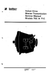
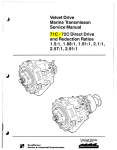
Velvet Drive
Marine Transmisson
Service Manual
71C -72C Direct Drive
and Reduction Ratios
1.5:1, 1.88:1, 1.91 :1 ,2.1 :1,
2.57=1 ,2.91 :1
-r<ì¡^,---<
Borg-Warner
.Automotive,
lnc.
Transmission
Systems
Post Office
Box 2688
Muncie
lndiana
47302
Telephone
31 7 286.6100
Telex
27491
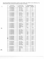
This manual reflects the transmission models as of April 1986. Later models may have ditferences. The
following direct-drive and reduction models are covered in this manual:
q
Transmission
Previous Trans.
Assemblv Number
Assemblv Number
10-17-000-001
Reverse
AS1-71C
1:1
1:1
0-1
7-000-002
AS1-71CR
1:1
1
0-1
7-000-003
AS1-71C8
1:1
11
11
1
0-1
7-000-004
AS1-71CBR
1:1
1:1
1
0-1
7-000-005
AS2-71C
1.52:1
1.52:1
10-17-000-006
AS2-71CR
1.52:1
1.52:1
10-17-000-007
AS7-71C
1.91:1
1
10-17-000-008
AS7-71CR
'1
.91:1
1.91:1
7-000-009
.91:1
AS3-71C
2.10:1
2.10:1
10-17-000-010
AS3-71CR
2.10:1
2.10:1
10-17-000-01
AS14-71C
2.57:1
2.57:1
10-17-000-012
AS14-71CR
2.57:1
2.57:1
10-1 7-000-013
AS15-71C
2.91:1
2.91:1
10-17-000-014
AS15-71CR
2.91:1
2.91:1
10-17-000-015
AS20-71C
1:1
1:1
10-17-000-016
AS20-71CR
1:1
11
None
1.88:1
1.88:1
AS11-72C
1:1
1.10:1
1
0-1
0-1 7-000-1
1
08
10-18-000-001
1
0-1
8-000-002
AS11-72CR
1:1
1
1
0-1
8-000-003
AS12-72C
1.52:1
1.68:1
AS12-72CR
1.52:1
1.68:1
None
1.88:1
2.07:1
10-18-000-004
1
0-1 8-000-1
1
0-1
06
8-000-005
.10:1
AS17-72C
1
.91:1
2.10:1
10-18-000-006
AS17-72CR
1.91:1
2.10:1
1o-18-ooo-oo7
AS13-72C
2.1O:1
2.31:1
AS13-72CR
2.10:1
2.31:1
10-18-000-009
AS14-72C
2.57:1
2.83:1
10-18-000-010
AS14-72CR
2.57:1
2.83:1
10-18-000-01
1
(e
Forward
1
1
Y
Transmission Ratio
0-1
8-000-008
AS15-72C
2.91:1
3.20:1
10-18-000-012
AS15-72CR
2.91:1
3.20:1
10-18-000-013
AS20-72C
1:1
1
.10:1
10-18-000-014
1
.10:1
1
AS20-72CR
11
10-18-000-015
None
11
1.10:1
06
None
1:1
1
.'10:1
10-18-000-017
None
1:1
1
.10:1
1
0-1 8-000-1
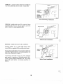
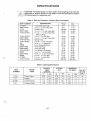
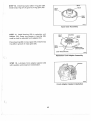
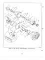
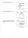
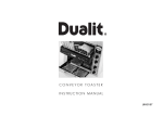
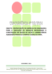
DESCRIPTION
t
COOLER OUTLET
(sEE FlG. 78, PAGE 28)
SHIFT LEVER
BBEATHER
f-\F
DIPSTICK
=_7fl
COOLER RETURN
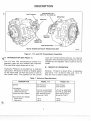
NOTE: SHOWN WITHOUT REDUCTION UNIT
Figure 1. 71C and 72C Transmission Assembly
C A.
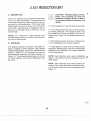
INTRODUCTION (See Figure
1).
valve are forward-neutral-reverse. An internal
regulator valve controls system pressure. Oil discharged by the regulator valve is sent to the oil
The 71C and 72C transmissions consist of a
planetary gear set and multiple disc clutches. cooler.
The input and output shafts are in line.
B.
THEORY OF OPERATION.
Hydraulic Pressure is provided by a crescent
type pump. The pump is driven at engine speed General. Forward is direct drive. A planetary
by the input shaft. Oil from the pump is sent to
gear set (1.1 to 1.0 ratio for72C, and 1.0 to 1.0
the control valve. The positions on the control ratio for 71C) is used to obtain reverse.
Table 1. Technical Specifications
DESCRIPTION
Speeds
Horsepower
Gasoline (maximum)
Diesel (maximum)
Torque and lnput Speed
Approximate Dry Weight
Direct Drive
Reduction
MODEL 71C
MODEL 72C
One Forward
One Reverse
One Forward
One Reverse
310 HP @ 4200RPM
475 HP @ 4200 RPM
274 HP @ 3200 RPM
182 HP @ 3200 RPM
See Ratings Charts
(Form No. 1237)
95
tb.
145 lb.
See Ratings Charts
(Form No. 1237)
109 tb.
153 lb.
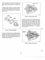
The transmission oil pump is driven by the input
shaft. lt supplies oil pressure to operate the
clutch packs, lubricate parts, and provide cooling.
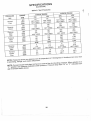
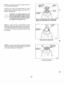
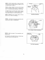
A damper plate is bolted to the engine flywheel.
The damper plate is splined to connect to the input shaft. The damper plate reduces torsional vibrations to the transmission from the engine.
(See Figure 2).
ENGINE
FLYWHEEL
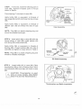
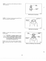
Figure 3. Forward Power Flow
DAMPER
ASSEMBLY
FLYWHEEL
HOUSING
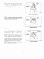
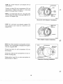
Reverse. The reverse clutch is applied hydraulically when the shift lever is placed in the reverse
position (See Figure 4). The applied clutch holds
the ring gear. The input shaft and sun gear,
driven by the engine, drive pinions, which drive
the carrier output shaft. The output shaft turns
opposite to engine rotation at a 1.1 to 1 speed reduction ratio for model 72C, and 1 to 1 speed ratio for model 71C.
TRANSMISSION
Figure 2. Typical Installation
Forward, The forward clutch is applied hydraulically when the shitt lever is placed in the forward
position. This connects the input shaft to the output shaft. The unit then transmits power at a 1 to
1 speed ratio in the same direction of rotation as
the engine (See Figure 3).
Figure 4. Reverse Power Flow
2
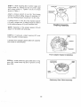
q.
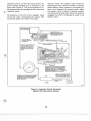
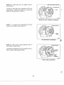
Hydraulic Circuit. Oil from the sump enters
pump suction passage and is directed to
pump (See Figure 5). The pump supplies oil
der pressure through passages to the control
regulator
valves.
the
the
unand
Selector Valve. The selector valve shifts the
transmission from neutral to forward or reverse.
When selector valve is placed in the forward position, oil is directed to the forward clutch. When
the selector valve is placed in reverse position,
oil is fed to the reverse clutch. When one clutch is
engaged the other is exhausted by a slot in the
Oil pressure on the end of the regulator valve
moves the valve, compressing the spring. This selector valve.
movement allows oil to flow to the cooler.
REGULATOR VALVE EXHAUSTS TO SUMP WHEN
PUMP PBESSUBE EXCEEOS
APPROXIMATELY 2OO P.S.I.
:5hi^î^""J,iÈb"f;^.,',';'
ORREVEHSE
5,"å'-,,,,,,o,oo''-"o'-'-Ecro'R'NG
|.l
--ì|<¡.ANDR.ONLY
^ I'lI l¡l
lÇ
REVEBSE CLUICH PFESSURE
TAP A 1/4' PIPE PLUG LOCATED IN ADAPTER AT TOP
CENTER OR,I/8" PIPE PLUG
CENTERED AT REAR OVEF
VALVE.
iq
FORWAFD CLUTCH FEED DOES NOT HAVE AN
EXTERNAL TAP FOF CHECKING PRESSUHE.
WHEN SELECTOR IS IN "F'' POSITION, LINE
PBESSURE INDICATES CLUTCH PRESSURE.
PRESSURE DROP FROM "N'' TO "F'' INOICATES
LEAKAGE IN FOFWARD CLUTCH CIRCUIÏ
INSTALL COOLER IN A POSITION
WHICH WILL INSURE IT IS FILLED
WITH OIL AT ALL TIMES, AND
WILL NOT DRAIN BACK TO SUMP.
IMPORTANT. ALL EXTERNAL OIL LINES AND
FITTINGS SHOULD HAVE MINIMUM INSIDE
DIAMETEF OF 13/32 INCH. COOLER MUST
PERMIT FREE FLOW OF FLUID FROM
REGULATOF VALVE.
COOLER RETUFN
TO SUMP
Figure 5. Hydraulic Circuit Schematic
(Model 72C Direct-Drive Shown)
re
3
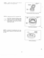
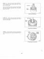
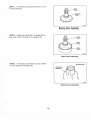
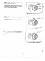
STEP
1. lf removed, install the following parts in
PIPE PLUGS
case (98). Tighten threaded parts to torque
BREATHER
shown in Table 4.
BEABING
Press bearing (7) into back of case (98).
Apply loctite #92, or equivalent, to threads of
pipe plugs (96 and 97)and thread into top of case
(e8).
DIPSTICK
TUBE
Apply loctite #592, or equivalent, to threads of
dipstick tube (18) and thread into side of case
ê
t
SNAP BING
GROOVE IN
BEARING MUST
FACE AWAY
FROM CASE
1264A4
Case Assembly
(e8),
NOTE: Plug (88) is a plastic shipping plug and
should be installed hand{ight.
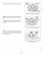
STEP
2. lnstall shield (92) in case (98) with slot
facing bottom of case (98). lnstall washer
(91)
and spring (90) inside shield (92).
Apply loctite #92, or equivalent, to threads of
bushing (89). Thread bushing (89) into side of
case (98) and tighten to torque shown in Table 4.
DRYSEAL
NOTE: Plug (88) is a plastic shipping plug and
€
should be installed hand{ight.
Oil Shield Assembly
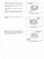
STEP 3. lnstall baffle (87) in case (98). Place
thrustwasher (86) on face of bearing bore. Notch
in thrustwasher (86) must align with notch in case
(e8).
CAUTION: Thrustwasher is used
only on some models. (See Model
Chart 71C and 72C Transmissions.)
Thrustwasher and Baffle Installation
(
14
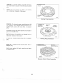
STEP 4. Lubricate sealing rings (83) and bushings (84) with vasoline.
r
SEALING
RINGS
lf removed, press bushings (8a) into pinion carrier (BS).
[-r" -l CAUTION: Do not block pressure
i lf\ | holes in pinion carrier (BS) with
bushings (8a).
L!d= |
lnstall sealing rings (83) in grooves of pinion carrier (85). Compress each sealing ring (83) until it
locks in place.
Pinion Carrier Assembly
lnstall pinion carrier (85) in case (98).
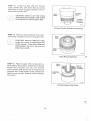
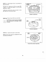
STEP
5.
lnstall pressure plate (74) in ring gear
PRESSURE
PLATE
(76).
RING
GEAR
Pressure Plate Assembly
6. Starting with a friction clutch ptate (70),
alternately stack friction clutch plates (73) and
steel clutch plates (72).
STEP
Place pressure plate (71) on top of clutch plates
(72 and73).
Forward Glutch Pack Arrangement
ii
15
STEP 7. lnstall clutcl-r plates (72 and 73) and
pressure plate (71) in ring gear (76).
PRESSURE
PLATE
RING
GEAR
Forward Clutch Pack Assernbly
STEP 8. lnstall snap ring (70) in ring gear (76).
PRESSURE
PLATE
CAUTION: Several different snap
rings are used to assemble the
clutch group. They have different
thicknesses. Be sure the correct
snap ring is used.
Snap Ring lnstallation
I
STEP L Lubricate O-ring (66) lightly with vasoline and install in groove of forward clutch cylinder (64).
O-Ring lnstallation
{
16
STEP 10, Lubricate clutch spring bearing ring
(68) and piston sealing ring (67) with vasoline.
CLUTCH SPBING
BEAR¡Nç R¡NG
PISTON
lnstall clutch spring bearing ring (68) in groove on
piston (65) face.
lnstall piston sealing ring (67) in outer groove of
piston (65).
PISTON
NOTE: Check that piston sealing ring (67) is not
SEALING RING
twisted, cut, or deformed. Replace if damaged.
Clutch Rings lnstallation
STEP 11. lnstall piston (65) in forward clutch cylinder (64).
Piston lnstallation
STEP 12. Place clutch belleville (dish) spring
(69) inside rim of forward clutch cylinder (64).
Spring is dished. The inside of the spring should
be lower than the outside.
CLUTCH BELLEVILLE
SPRTNG (DTSHED)
Clutch Spring Assembly
l
17
STEP 13. lnstall ring gear (76) over forward
clutch cylinder (64), with piston (65) and spring
(69)facing up. Press ring gear (76) down over forward clutch cylinder (64).
L¿:¡i
EXTERNAL
TEETH
CAUTION: Check to see that clutch
spring bearing ring (68) is stillseated
in the groove of clutch piston (65).
FORWARD
CLUTCH
CYLINDER
126524
Forward Ch,¡tch Cylinder lnstallation
STEP 14. Remove clutch assembly from press.
lnstall snap ring (60) in groove of ring gear (76).
ru
CAUTION: Several different snap
rings are used to assemble the
clutch group. They have different
thicknesses. Be sure the correct
snap ring is used.
Snap Ring lnstallation
STEP 15. Place ring gear (76) in press with external splines facing down. Assembly tool should
support the ring gear (76) only. The forward
clutch cylinder (64) should not be touching the
assembly tool. Press forward clutch cylinder (74)
against snap ring (60). Remove clutch assembly
from press.
(
ASSEMBLY
TOOL
Compressing Clutch pack
(
18
STEP 16. Push down, by hand, on clutch plates.
Measure snap ring gap. Select proper thickness
snap ring (75) or combination of snap rings (75)
to set clutch pack clearance. Refer to chart below. More than one snap ring may be required.
Clearance
Clearance
Clearance
Clearance
for
for
for
for
bronze pack (71C)bronze pack (72C)paper pack (71C)paper pack (72C\-
FART
0.018"-0.053,
0.035"-0.055"
0.018"-0.053"
0.021 ,,-0.046,,
SNAP RING THICKNESS
NUMBER
tn.
mm
4768
.050-.054
.074-.078
.096-.100
.062-.066
.033-.037
.050-.054
1.3-1.4
1.9-2.0
47684
47688
10-00-139-018
10-00-139-048
1 0-00-1 39-049
Snap Ring Selection
2.4-2.5
1.6-1.7
.84-.94
1.27-1.37
STEP 17. lnstall selected snap ring(s) (75) in
groove of ring gear (76).
SNAP
SNAP RING
RING
\
RING
GEAR
Snap Ring Assembly
I
I
STEP 18. lf removed, installwoodruff key (81)in
drive gear assembly (82). Slide forward clutch
hub (80) on drive gear assembly (82) and align
with woodruff key (81). Press forward clutch hub
(80) on drive gear assembly (82) and against
shoulder.
FORWARD CLUTCH HUB
sEALrNc
R,NGS
I
I
I
I
lnstall snap ring (79) in groove of drive gear assembly (82).
DRIVE GEAR
ASSEMBLY
Lubricate sealing rings (78) with vasoline and install in grooves of drive gear assembly (82).
Sealing Ring lnstallation
Compress each sealing ring (78) until it locks in
place.
19
STEP 19. lnstall drive gear assembly (82) in
clutch assembly. Slide bearing (63) down drive
gear assembly (82).
Place complete assembly in press. Press bearing
(63) into drive gear assembly (82) until seated
against shoulder.
Bearing !nstallation
STEP
20.
lnstall snap rings (61 and 62)
in
grooves of drive gear assembly (82) and forward
clutch cylinder (64).
Snap Ring lnstallation
STEP 21. Apply vasoline to bronze thrustwasher
(77). lnstall over end of shaft and against face of
gear.
Thrustwasher Assembly
(
20
STEP 22. lnstall clutch and drive gear assembly
(82) in case (98).
.,
t
Rotate clutch and drive gear assembly (82) back
and forth to engage ring gear teeth with pinion
gear teeth.
Clutch and Drive Gear lnstallation
STEP 23. lf original case and clutch cylinder are
used, install thrustwasher (59) on face of clutch
cylinder.
FACE OF
CLUTCH
CYLINDER
On model 10-18 transmissions select new
thrustwasher (59) as follows:
I
THRUST
Position case vertically as shown. Measure from
face of case (98), without gasket (49), to face of
clutch cylinder.
(
When dimension is 0.433 inch ('11.0 mm) or
use 71-158 thrustwasher.
less,
Thrustwasher lnstallation
When dimension is greater than 0.433 inch (11.0
mm), use 10-16-193-001 thrustwasher.
STEP 24. lnstall one bronze reverse clutch friction plate (56) in case (98).
REVERSE
CLUTCH
FRICTION
PLATE
o
l\À
1
Friction Plate lnstallation
I
21
26544
25. lnstall three dowel pins (58) and
eleven pressure plate springs (57) in case (98).
STEP
1
26554
Spring and Dowel Pin lnstallation
STEP 26. lnstall one steel separator plate (55) in
case (98) with large part of tab to left of dowel pin
LARGE
SIDE OF
TAB HERE
(58).
DOWEL
PIN
Alternately stack remaining reverse clutch friction plates (56) and steel separator plates (55) in
case (98).
-/'
--J
C^ r//
-
Reverse Clutch Pack lnstallation
0
STEP 27. lnstall reverse clutch pressure plate
(54) in case (98) with three half moons aligned
with dowel pins (58). Be sure all springs are
seated in their holes.
Pressure Plate lnstallation
(
22
STEP 28. Lubricate sealing ring (S2) with vasoline and install in groove of reverse clutch piston
REVERSE CLUTCH
(51)
NOTE: Be sure sealing ring (52) is not twisted,
cut or distorted. Replace if damaged.
SEALING
RING
Sealing Ring Assembly
STEP 29. I'tremoved, press needle bearing (48)
into adapter (45). Needle bearing must be installed flush (even) with back face of adapter
FORWARD AND
REVERSE
ADAPTEB
SEALING
RING
NEEDLE
BEARING
(45).
Lubricate O-ring (53) with vasoline and install in
groove of adapter (45).
NOTE: Be sure O-ring (52) is not twisted, cut, or
distorted. Replace if damaged,
(.,
lf removed,
install dryseal plug (S0) in adapter
Sealing Ring Installation
(4s).
STEP 30. lnstall reverse clutch piston (S1) in
adapter (45).
FORWARD AND
REVERSE ADAPTEB\
Lightly coat gasket (a9) with vasoline and place
on adapter (45).
Reverse Clutch Piston Assembly
(
23
STEP 31. lnstall adapter (45) on case (98) and
align bolt holes.
Thread four capscrews (46) into case (98).
Tighten in a criss-cross pattern to final torque
specified in Table 4.
Lightly tap woodruff key (44) into place in drive
gear (82) with a soft-faced mallet.
Adapter lnstallation
STEP 32. Press oil seal (42) into PumP bodY.
GAUTION: Oil seal must be installed
dry, Lubricants can damage rubber
coating.
Oil Seal lnstallation
STEP
0
33. lnstall driven gear in pump body.
NOTE: Pump gear should be installed the same
side down as removed.
Pump Driven Gear Assembly
a
24
STEP 34. Lubricate pump gasket (43)with vasoline and install in groove of adapter (47).
lnstall pump drive gear onto input shaft (82).
Check that pump drive gear locates freely on
woodruff key (44) and shaft (82).
ffiJÀ,
Pump Gasket lnstallation
STEP 35. lnstall pump assembly (40) on top of
adapter (47) and align bolt holes.
CAST
ARROW
CAUTION: Position pump housing
with cast arrow at top pointing in the
same direction as engine rotation.
Thread four bolts (41) into adapter (47). Tighten
in a criss-cross pattern to finaltorque specified in
Table 4.
Pump Assembly lnstallation
f\
STEP 36. Assemble controlvalve assembly (33).
Refer to Figure 6,
Lubricate O-ring (38) with vasoline and install on
end of valve assembly (33).
NOTE: Gap in snap ring must be aligned with
notch in control valve.
s
R
I
Valve Assembly
{
25
2693A
STEP 37. Lubricate controlvalve O.D. Slide control valve assembly (33) into side of case (98).
(
Valve Assembly lnstallation
STEP 38. lnstall switch cam (31) on end of valve
assembly (33). Be sure tab on switch cam (31)
sets in notch of valve assembly (33).
SWITCH CAM
Switch Cam lnstallation
f1
Y
STEP
39. lnstall valve
cover (28) as follows:
Position gasket (31) on case (98). Place valve
cover (28) over gasket (32) and align bolt holes.
Thread three bolts (29) and lockwashers (30) into
case (98). Tighten bolts in a criss-cross pattern to
final torque specified in Table 4.
7
lf removed, lubricate O-ring (27) with vasoline
and install in groove of neutral switch (26).
Thread neutral switch assembly (25) into valve
cover (28) and tighten to torque specified in
Valve Cover lnstallation
Table 4.
€
26
STEP
40. lnstall shift lever (19) as follows:
Lubricate poppet spring (24) and hole in case
(98) with grease, shell alvania #2 or equivalent.
Place poppet spring (24) and steet bail (20) in
case (98).
Slide shift lever (19) over end of control valve assembly (33) and against steet bail (23). Rotate
shift lever (19) to engage steet bail (23) in hote of
shift lever (19).
Hold shift lever (19) against steet bail (23). tnstail
washers (21 and 22) and thread nut (20) on con_
/\
POPPET SPRING
STEEL BALL
ROL VALVE
LOCKWASHER
FLATWASHER
Shift Lever Assembly
trol valve assembly (33). Tighten nut (20) to
torque specified in Table 4.
STEP
41. lnstall bearing
retainer (3) as follows:
lf removed, press oil seal (6) into bearing retainer
(3).
CAUTION: Oil Seal must be installed
dry. Lubricants can damage rubber
coating.
{
retainer (3) on back
and lockwashers (b)
(4), in a criss-cross
pattern, to torque shown in Table 4.
Bearing Retainer
STEP 42. Slide coupting (2) on output shaft.
Thread nut (1) on output shaft. Tighten nut (1)to
torque shown in Table 4.
Coupling Installation
27
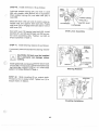
STEP 43. lnstalldipstick (17)in side of case (98)'
Turn handle until snug. Do not overtighten'
NOTE: For assembly of reduction units refer to
the sections in the back of this manual'
f
DIPSTICK
Dipstick lnstallation
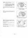
INSTALLATION
CAUTION: After a transmission failure the cooler and cooler lines must
be flushed to remove contaminated
hydraulic fluid and metal/rubber particles. Failure to comply can result in
premature wear or failure of overhauled transmission.
.
.
Align input shaft spline with damper plate.
Assemble transmission to engine, and then install bolts. Do not use bolts to draw transmission
against engine.
Çr
WARNING: CHECK THE SHIFT
LEVER AT THE HELM TO SEE THAT
FORWARD POSITION IS ALSO FOR.
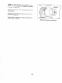
Figure 74. Sh¡ft Cable Adjustment
WARD POSITION AT THE TRANS.
MISSION SHIFT LEVER.
(TRANSMISSION SHOULD NOT BE
RUNNING IN REVERSE WHEN BOAT
rs GorNG FoRWARD.)
BREATHER
.
Adjust the shift cable so the holes in the shift
lever are centered over the detent ball at each
selector location. See Figure 74.
o
Read OEM manualfor complete installation instructions, lnstallation literature is available from
Borg-Warner Automotive-Transm ission Systems'
Request Form No.1131.
¡
Connect oil line to oil to the cooler outlet. See
Figure 78.
r27854
Figure 78. O¡l to Cooler Outlet
28
e
38\
'i \\
ML-ru*
25
TRANSMISSIONS
88
-- 72
5ì\
ONLY
,r/
N
(
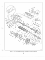
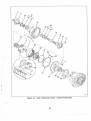
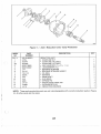
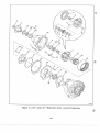
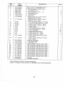
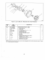
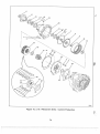
Figure 8.71C and72C Transmission Assemþly - Current Production
29
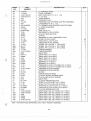
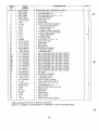
INDEX
PART
NO.
NUMBER
Fig.
1
I
1
0-1
1
0-1
7-000-.
8-000-.
4775L
454784
2
2A
3
45474Y
71-7
3A
72-7
4
00001 79859
1 0-00-1 83-043
00001 03322
4A
5
6
7
7A
7B
I
8A
I
9A
71C-110
B111AG
BsOSAGS
B3OgAGS
71-147
i?.'*
9B
10
'11
114
12
13
14
15
16
17
ll
174
10-17-559-001
10-13-559-001
18
19
71-798
20
941 8892
21
00001 08579
00001 03340
22
23
10-04-034-002
0000453632
24
71-42
25
10-00-640-004
NO NUMBER
10-00-141-046
26
27
28
29
30
00001 79796
00001 0331 9
31
10-16-039-001
32
71-14
71-A2444
33
34
35
36
37
38
10-16-039-001
4821
71-246
71-242
71-243
4804H
DESCRIPTION
QTY
TRANSMTSSTON ASSEMBLy (MODEL 71C)
TRANSM TSSION ASSEM BLy (MODEL 72C)
.
.
.
.
.
.
.
.
.
¡
o
¡
¡
.
.
.
.
.
.
.
.
.
.
.
.
.
.
.
.
.
.
.
.
.
.
o
.
.
.
.
.
.
.
.
.
.
.
.
OUTPUT SHAFT NUT
COUPLING (10-17 ONLY)
COUPLING (10-18 ONLY)
BEARING RETAINER (10-17 ONLY)
BEARING RETAINER (10-18 ONLY)
HEX HEAD BOLT 1z¡u-14 x 1-1lq) (10-17 ONLY)
HEX HEAD BOLT 1z¡u-14 x 1-11¿) (10-18 ONLY)
LOCKWASHER (1ro)(10-17 ONLY)
OIL SEAL
BEARING
BEARING
BEARING
BEARING RETAINER GASKET (10-17 ONLY)
BEARING RETAINER GASKET (10-18 ONLY)
ADAPTER
ADAPTER
ADAPTER
LOCK BOtt 1z¡u-14 x 7le)
LOCKWASHER (4re) (10-18 ONLY)
LOCKWASHER (4ro) (10-17 ONLY)
HEX HEAD BOLT 1z¡u-14 x 1-31+)
LOCKWASHEn g¡u¡
ADAPTER GASKET
BEARING
RETAINING RING
DIPSTICK (ALL DIRECT DRIVES EXCEPT -01s AND -016)
DIPSTICK (FOR -015 AND -016)
DIPSTICK TUBE
SHIFT LEVER
HEX NUT 1s¡u-20,
1
1
1
1
1
6
6
6
1
1
1
1
1
1
1
1
1
6
6
6
2
2
1
1
1
1
1
'1
1
1
LOCKWASHEn 1s¡u¡
1
FLATWASHER (s/re)
1
STEEL BALL 1s¡u¡
1
POPPET SPRING
NEUTRAL SWITCH ASSEMBLY
o NEUTRAL SWITCH (NSS)
. O-RING
. VALVE COVER
HEX HEAD BOLT (tla-lg y t¡.¡
LOCKWASHEn
1t7o¡
SWITCH CAM
VALVE COVER GASKET
CONTROL VALVE ASSEMBLY
. SNAP RING
. SPRING RETAINER
. VALVE SPRING
. REGULATOR VALVE
. O-RING
{
1
1
1
1
1
3
3
1
1
'l
1
1
1
1
1
*
REFER TO ASSEMBLY NUMBER ON lD TAG (See Figure 1)
REFER TO REDUCTION SECTION IN BACK OF MANUAL.
NSS - NOT SERVICED SEPARATELY BUY NEXT HIGHER ASSEMBLY
-*
30
e
|
INDEX
æ
v
39
40
71-2444
41
10-00-183-021
42
43
44
45
46
47
48
49
50
10-00-044-014
3-61
4873
71C-A8
4911
NO NUMBER
4840D
71-1448
0000444858
71-35
52
53
54
55
56
57
58
48054
584
588
R6-177
59
71-158
594
10-1 6-193-001
60
4822
61
R6A-7112
614
47668
62
4734
624
45594
63
B1O7A
B1O8A
64
644
I
71C-A60
51
634
4804G
71-71
72-176
72-4668
71-97
71-874
46228
71-70
72-70
65
10-1 6-124-001
654
71-45
66
5M-122
67
5L-36
68
69
70
3-37
71
5C-1 754
72
724
3-176
3-176
73
sc-A66A
734
5c-A664
74
75
5L-67
10-00-139-048
1 0-00-1 39-049
4768
754
758
75C
:,:-*r. f
PABT
NUMBER
NO.
\,
.rsrlj¡,j<F¿rf
5C-33
4755
75D
47684
47688
75E
10-00-139-018
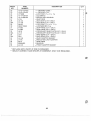
DESCRIPTION
.
CONTROL VALVE
PUMP ASSEMBLY
HEX HEAD BOLT 1s¡u-18 x 1-3/e)
. OIL SEAL
PUMP GASKET
WOODRUFF KEY
FORWARD AND REVERSE ADAPTER ASSEMBLY
CAPSCREW (3/e-16 x 1-11+)
. FORWARD AND REVERSE ADAPTER (NSS)
. NEEDLE BEARING
GASKET
PIPE PLUG (1/4)
REVERSE CLUTCH PISTON
CLUTCH SEALING RING
O.RING
REVERSE CLUTCH PRESSURE PLATE
STEEL CLUTCH PLATE
FRICTION CLUTCH PLATE
PRESSURE PLATE SPRING
DOWEL PIN (.312 DIA x .438 LONG)
DOWEL PIN (.312 DIA x .621 LONG)
DOWEL PIN (.312 DIA x .875 LONG)
THRUSTWASHER
THRUSTWASHER
SNAP
SNAP
SNAP
SNAP
SNAP
RING
QTY
1
1
4
1
'1
1
1
4
1
1
1
1
1
1
1
1
0-2
1-3
11
3
3
3
1
1
1
R|NG (10-17 ONLY)
RING (10-18 ONLY)
R|NG (10-17 ONLY)
R|NG (10-18 ONLY)
BEARTNG (10-17 ONLY)
BEARING (10-18 ONLY)
FORWARD CLUTCH CYLTNDER (10-17 ONLY)
FORWARD CLUTCH CYLTNDER (10-18 ONLy)
FORWARD CLUTCH PISTON
FORWARD CLUTCH PISTON
O-RING
PISTON SEALING RING
CLUTCH SPRING BEARING RING
CLUTCH BELLEVILLE SPRING
SNAP RING
CLUTCH PRESSURE PLATE
STEEL CLUTCH PLATE (10-17 ONLY)
STEEL CLUTCH PLATE (10-18 ONLY)
FR|CT|ON CLUTCH PLATE (10-17 ONLY)
FR|CT|ON CLUTCH PLATE (10-18 ONLY)
CLUTCH PRESSURE PLATE
SNAP RING (.033-.037 THrCK)(10-17 ONLY)
SNAP RING (.050-.054 THICK) (10-17 ONLY)
sNAp RrNG (.050-.054 TH|CK)(10-18 ONLY)
SNAP RrNG (.074-.078 THICK)(10-18 ONLY)
SNAP RrNG (.0e6-.100 TH|CK)(10-18 ONLY)
SNAP RrNG (.062-.066 THrCK)(10-18 ONLY)
NSS - NOT SERVICED SEPARATELY BUY NEXT HIGHER ASSEMBLY.
31
1
1
1
1
1
1
1
1
1
1
1
1
1
1
1
1
4
6
5
7
1
1
1
1-2
1
1
1
NO.
764
77
78
79
80
71-17
804
81
10-16-179-001
000021 821 1
814
00001 24553
82
71C-3A16
72C-2A16
4806J
4495
71-40
824
48068
83
84
85
86
A4877D (KtT)
**
0-1 7-659-*
**
10-'1 8-659-*
71-159
864
10-17-193-001
87
71-140
71B'-140
10-00-191-002
1
854
874
88
89
48858
90
5L-222
91
35-1 43
92
93
72C-98
71C-84
94
71C-A98
A4740G
0000444866
0000444687
**
1 0-1 7-565-*
**
g-565-*
1 0-1
95
96
97
98
984
*
R|NG GEAR (10-17 ONLY)
R|NG GEAR (10-18 ONLY)
THRUSTWASHER
SEALING RING
SNAP RING
FORWARD CLUTCH HUB (10-17 ONLY)
FORWARD CLUTCH HUB (10-18 ONLY)
wooDRUFF KEY (10-17 ONLY)
wooDRUFF KEY (10-18 ONLY)
DRTVE GEAR ASSEMBLY (10-17 ONLY)
DRIVE GEAR ASSEMBLY (10-18 ONLY)
SEALING RING
BUSHING
prNroN CARRTER ASSEMBLY (10-17 ONLy)
ptNroN CARRTER ASSEMBLY (10-18 ONLy)
THRUSTWASHER
THRUSTWASHER
OIL BAFFLE
OIL BAFFLE
PLUG (3/a-18)
DRYSEAL BUSHING (31¿-1 4)
SPRING
FLAT WASHER
OIL INLET SHIELD
OIL RETURN TUBE
OIL STRAINER ASSEMBLY
BREATHER
PIPE PLUG (3/a-18)
PIPE PLUG (1la-27)
CASE (10-17 ONLY)
CASE (10-18 ONLY)
71-6
72-6
76
**
DESCRIPTION
PART
NUMBER
INDEX
OTY
1
1
(
1
2
1
1
,|
1
1
1
1
4
2
1
1
1
1
1
1
2
1
,l
1
1
1
1
1
€
1
1
1
1
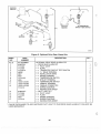
CHECK MODEL CHART TO DETERMINE CORRECT PART NUMBER
NOTE: The following kits are ava¡lable for the Model 71C and 72C transmissions. lndex numbers shown
match the index numbers on the exploded-view, Figure 8.
NO.
71
DESCRIPTION
PART
NUMBER
INDEX
A4B67AB
5C-175A
724
734
3-1
74
5L-67
76
5C-A664
OTY
FORWARD CLUTCH PACK Krr (10-18 ONLY)
.
.
.
.
CLUTCH PRESSURE PLATE
STEEL CLUTCH PLATE
FRICTION CLUTCH PLATE
CLUTCH PRESSURE PLATE
1
6
7
1
6
32
q
DESCRIPTION
INDEX
PART
NO.
NUMBEB
FORWARD CLUTCH PACK Klr (10-17 ONLY)
. CLUTCH PRESSURE PLATE
. STEEL CLUTCH PLATE
. FRICTION CLUTCH PLATE
. CLUTCH PRESSURE PLATE
A4867AE
71
72
73
74
5c-1754
3-1
76
5C-4664
5L-67
NO.
OIL SEAL AND SEALING RING KIT
. OIL SEAL
A4867HA
6
38
42
43
52
53
66
67
78
83
71C-1 10
4804H
10-00-044-014
3-61
48054
4804G
5M-122
5L-36
4806J
48068
10-00-044-017
LÉH€=Êê2
.
.
.
.
.
.
.
.
.
.
.
1
4
5
1
QTY
1
O-RING
OIL SEAL
PUMP GASKET
CLUTCH SEALING RING
O-RING
O-RING
CLUTCH SEALING RING
1
SEALING RING
2
SEALING RING
OIL SEAL (REDUCTION UNITS ONLY)
SERVICE GASKET KIT (FOR CONTENTS SEE
NEXT KIT LIST)
4
1
1
1
1
1
1
DESCRIPTION
PART
INDEX
NO.
8
8A
14
32
49
DESCRIPTION
PART
NUMBER
INDEX
QTY
1
1
OTY
NUMBER
10-17-410-002
71-147
72-147
L4-1 46
71-14
71-1448
L4-145
L4-147
INDEX
PART
NO.
NUMBER
10-04-420-052
10-04-539-001
10-00-640-004
25
28
29
30
00001 79796
00001 0331
31
10-16-099-001
32
71-14
10-16-039-001
I
1
340
SERVICE GASKET KIT
BEARING RETAINER GASKET
BEARING RETAINER GASKET
ADAPTER GASKET
VALVE COVER GASKET
GASKET
GASKET (REDUCTION UNITS
GASKET (REDUCTION UNITS
.
.
.
.
.
.
.
(10-17 ONLY)
(10-18 ONLY)
1
1
ONLY)
ONLY)
NEUTRAL SWITCH KIT
. SWITCH AND BODY ASSEMBLY
. . NEUTRAL SWITCH ASSEMBLY
. . VALVE COVER
. HEX HEAD BOfr 1t¡o-29 , 't,r,
. LOCKWASHER (1/a)
. SWITCH CAM
. VALVE COVER GASKET
. INSTRUCTION SHEET
33
1
1
DESCRIPTION
d.
1
1
1
QTY
1
1
1
3
3
1
1
1
NO.
15
DESCRIPTION
PART
NUMBER
INDEX
10-95-410-002
4766
34
60
4821
61
R6A-7112
614
47668
62
4734
624
45594
70
75
4755
1
754
758
10-00-139-049
4768
75C
75D
47684
47688
758
10-00-139-01
79
4495
4756D
4756E
4822
0-00-1 39-048
481 6
47664
I
SNAP RING SERVICE KIT
. RETAINING RING
. SNAP RING
. SNAP RING
. SNAP RING (10-17 ONLY)
. SNAP RING (10-18 ONLY)
. SNAP RING (10-17 ONLY)
. SNAP RING (10-18 ONLY)
. SNAP RING
. SNAP RING (.033-.037 THICKXIO-17 ONLY)
. SNAP RING (.050-.054 THICKXIO-17 ONLY)
. SNAP RING (,050-.054 THICKXI0-18 ONLY)
. SNAP RING (.074-.078 THICKXIO-18 ONLY)
. SNAP RING (.096-.100 THICKXI0-18 ONLY)
. SNAP RING (.062-.066 THICKXI0-18 ONLY)
. SNAP RING
. SNAP RING (REDUCTION UNITS ONLY)
. SNAP RING (REDUCTION UNITS ONLY)
. SNAP RING (REDUCTION UNITS ONLY)
. SNAP RING (REDUCTION UNITS ONLY)
OTY
1
'l
1
1
1
2
1
1
1
1
2
1
1
1
1
1
1
1
1
{
{
34
TRANSMISSION
MODEL NUMBER
CASE ASSEMBLY
NEW STYLE
W/O BUSHINGS
CASE ASSEMBLY
OLD STYLE
W/BUSHINGS
FORWABD PINION
CARRIEB ASSEMBLY
NEW STYLE
WSEALING RINGS
FOBWABD PINION
CARRIEB ASSEMBLY
OLD STYLE WO
SEALING RINGS
71-1AzC
71-1p.24
71-A1K
10-'t7-659-018
1 0-1 7-659-020
1 0-1 7-659-020
71-A1K
1
0-1 7-659-01
I
71-1AzC
72-A1J
72-A1J
1
0-1
8-659-006
72-142
NOT USED
'10-18-659-006
72-142
10-'t8-565-002
0-1 8-565-002
1 0-1 8-565-002
1 0-1 8-565-002
1 0-1 8-565-002
1 0-1 8-565-002
1 0-1 8-565-002
1 0-1 8-565-002
1 0-1 8-565-002
1 0-1 8-565-002
1 0-1 8-565-002
1 0-1 8-565-002
1 0-1 8-565-002
1 0-1 8-565-002
72-A1K
72-A1K
72-A1K
72-A1K
72-A1K
72-A1K
72-A1K
10-'r8-659-014
1 0-1 8-659-01 4
1
0-1
0-1 8-565-001
72-A1J
1
0-1
NOT USED
L4-4150
L4-4150
L9-4150
L9-4150
1 0-1 7-659-006
10-17-659-010
1 0-1 7-659-007
1 0-1 7-659-007
1 0-1 7-659-008
1 0-1 7-6s9-008
NOT USED
NOT USED
NOT USED
NOT USED
NOT USED
72-A1K
1
0-1 8-659-01 2
7'18-14
0-1
0-1
10-.17-065-006
71C-1
71C-1
1
0-1 7-659-01 2
1
0-1 7-659-01 2
71-A1K
1
0-1
71-A1K
7-659-020
1 0-1 7-659-020
71-A1K
1
0-1 7-659-01 8
1
0-1 7-659-01
7.t-A1K
1
0-1 7-659-01 6
1
0-1
71-A1K
1
0-1 7-659-01 6
1
0-1
1
I
7-000-002
7-000-003
0-1 7-000-004
0-1 7-000-005
0-1 7-000-006
0-1 7-000-007
0-1 7-000-008
0-1 7-000-009
0-1 7-000-01 0
0-17-000-01
1
o-17-OOO-012
0-1 7-000-01 3
0-1 7-000-01 4
0-1 7-000-01 5
1
0-1 7-000-01 6
0-1 7-000-1 08
1
0-1
7-065-006
1 0-1 7-565-002
1 0-1 7-565-002
1 0-1 7-565-002
1 0-1 7-565-002
1 0-1 7-565-002
1 0-1 7-565-002
1 0-1 7-565-002
1 0-1 7-565-002
1 0-1 7-565-002
1 0-1 7-565-002
1 0-1 7-565-002
1 0-1 7-565-002
1 0-1 7-565-002
1
0-1
718-14
71-A1K
71-A1K
71-A1K
71-A1K
71-A1K
71-A1K
0-1 7-659-01
71-1p.2
71-142A.
71-142p'
71-142C
71-142C
I
7-659-004
7-659-004
71-1AzC
71-142C
10-'17-659-018
1 0-1 7-659-01
I
71-1A.2C
71-1424
(lf used between
NOT
NOT
NOT
NOT
USED
USED
USED
USED
L4-4150
L4-4150
L9-4150
L9-4150
1 0-1 7-659-006
10-17-659-010
1 0-1 7-659-007
1 0-1 7-659-007
I 0-1 7-659-008
1 0-1 7-659-008
NOT USED
NOT USED
1 0-1 7-6s9-021
71-142
7'l-142
71-142
10-17-659-012
10-17-659-012
7-065-004
1 0-1 7-065-004
0-1 7-000-001
THRUSTWASHER
REDUCTION
PINION CARRIER
ASSEMBLY
REDUCTION
HOUSING
forward pinion carrier
NOT USED
NOT USED
NOT USED
NOT USED
NOT USED
NOT USED
NOT USED
NOT USED
10-17-065-001
1 0-1 7-065-001
7-065-003
7-065-003
10-'t7-065-002
1 0-1 7-065-002
1
0-1
1
0-1
assv and case)
1
0-1 7-1 93-001
't0-17-193-001
NOT USED
NOT USED
1
0-1 7-1 93-001
1
0-1 7-1 93-001
10-r 7-065-001
10-17-065-001
NOT USED
NOT USED
10-17-065-00't
NOT USED
NOT USED
10-17-065-001
NOT USED
NOT USED
1
0-1
0-1 7-1 93-001
10-17-'193-001
1
NOT USED
7-065-003
(¡)
(Jr
10-18-000-00'l
1 0-1 8-000-002
1 0-1 8-000-003
1 0-1 8-000-004
1 0-1 8-000-005
1 0-1 8-000-006
1 0-1 8-000-007
1 0-1 8-000-008
1 0-1 8-000-009
0-1 8-000-01 0
10-18-000-01 1
1 0-1 8-000-01 2
1 0-1 8-000-01 3
1
10-'t8-000-014
1
0-1 8-000-01 5
1
0-1 8-000-01 6
7
10-'t8-000-106
1
0-1 8-000-01
1
1
0-1 8-565-001
0-1 8-565-001
1
1
1
0-1
8-565-002
'10-18-659-012
1
0-1 8-659-01 2
1
0-1 8-659-01 0
10-18-659-010
8-659-002
1 0-1 8-659-002
72-1AzC
1
0-1
72-1Á.2C
8-659-004
1 0-1 8-659-004
1
0-1
1
0-1 8-659-01 2
72-142C
72-AtK
1
0-1 8-659-01 2
72-A1K
10-'t8-659-012
72-1A2C
72-1A2C
72-A'tK
72-A1K
72-A1K
72-A1K
72-A1K
'10-18-659-012
'10-18-659-014
1
0-1
10-'t8-659-014
1
0-1
.10-18-659-008
8-659-008
8-659-006
72-142C
8-659-002
8-659-002
72-1424
72-1424
72-1p.2
72-1A2C
Model Chart 71C and 72C Transmissions
1
0-1 7-659-021
NOT USED
NOT USED
1
0-1 7-065-001
1
0-1 7-065-001
7-065-003
1 0-1 7-065-003
1 0-1 7-065-002
1 0-1 7-065-002
1
0-1
0-1 7-065-001
10-17-065-001
1 0-1 7-065-001
1 0-1 7-065-001
1
NOT
NOT
NOT
NOT
NOT
USED
USED
USED
USED
USED
1 0-1 7-065-003
NOT USED
NOT USED
.10-17-193-001
1
0-1 7-1 93-001
NOT USED
NOT USED
10-17-193-001
10-'17-193-001
NOT
NOT
NOT
NOT
USED
USED
USED
USED
10-17-193-00',|
10-17-193-001
1 0-1 7-1 93-001
1 0-1 7-1 93-001
NOT USED
NOT USED
ls
l,/
IGNITION
SWITCH
TO TRANSISTOR
CIRCUIT TEST SWITCH
Figure 9. Optional Drive Gear Alarm Kits
INDEX
NO.
Fig
1
2
3
4
5
6
7
I
9
10
11
12
DESCRIPTION
NO NUMBER
A4867HN
71C-309
71C-308
OPTIONAL DRIVE GEAR ALARM KITS
71C-4312
4900E
4927
4924
71C-4102
4925
10-00-140-004
10-00-140-005
10-00-140-006
71C-310
13
A4867HS.
14
71C-309
71C-308
4924
71C-310
15
16
17
*
9
PART
NUMBER
. DRIVE GEAR ALARM KIT
. . PILOT LIGHT
. . PLATE
o . TRANSISTOR CIRCUIT TEST SWITCH
oo
1l+" MALE TERMINAL
. . INSTALLATION WIRE
. . SPADE TERMINAL
o . TEMPERATURE SWITCH
. . EYELET TERMINAL
. . TEMPERATURE SWITCH
. O FEMALE TERMINAL
. . FEMALE CONNECTOR
. . WIRING DIAGRAM
. . INSTîUCTION SHEET
. PILOT LIGHT KIT
. . PILOT LIGHT
. . PLATE
. . SPADE TERMINAL
o . WIRING DIAGRAM
. . INSTRUCTION SHEET
QTY
1
1
1
1
2
1
1
1
1
1
2
1
1
1
1
1
1
1
1
1
CAN BE PURCHASED TO ADD ANOTHER PILOT LIGHT TO THE DRIVE GEAR ALARM KIT. CAN NOT BE
USED SEPARATELY.
36
e
SPECIFICATIONS
CAUTION: Threaded plugs, screws, bolts, and coupling nuts must be
tightened to torque shown in this table to prevent premature failure
of transmission or reduction unit.
Table 4. Bolt and Fastener Torques (Non-Lubricated)
PART NUMBER
DESCRIPTION
941 8892
5Lta-24 Shift Lever Nut
00001 79796
1l¿-20
x
4775L
Coupling Nut
71rc-14
7l'ta-14
0-00-1 83-043
1
0-00-1 83-073
Nm
11-15
1-15
8-11
8-11
llzHex Head Bolt
00001 79859
1
FT.LB
x 1-11+ Hex Head Bolt
x 1-11+ Hex Head Bolt
1
160-2ô0
42-50
42-50
217-353
42-50
42-50
57-68
57-68
57-68
57-68
(Self Locking)
71rc-14
71rc-14
00001 79864
10-04-034-002
10-00-183-021
491
1
48858
0000444866
0000444687
10-00-640-004
Bolt
Dipstick Tube
5/ro-18 x 1 Hex Head Bolt
3/a-16 x 1-1la Capscrew
3/+-14 Dryseal Bushing
27-37
25-35
3/e-18 Pipe Plug
1la-27 Pipe Plug
17-27
7-12
e/r o-1
20-30
42-50
27-37
10-40
17-22
I
Switch Assembly
7ha-14 x 1-11+ Lock Bolt
3/e-18 x 1-1le Hex Head Bolt
s/ro-18 x 3/¿ Lock Bolt
7l'ta-14 x 4e Lock Bolt
Coupling Nut
485,3E
00001 79840
48538
477688
1
x Ze Lock Bolt
x 1-slq Hex Head
0-00-1 49-034
14-55
23-30
37-50
34-48
23-37
9-1 6
28-42
57-ô8
37-50
23-30
57-68
17-22
42-50
220-260
298-352
Table 5. Spring Dimensions
PART
NUMBEB
WHERE
USED
APPROX.
FREE
LENGTH
APPROX.
o.D.
DIAMETER
OF WIRE
ln.
mm
tn.
mm
tn.
mm
NO. OF
ACTIVE
COILS
71-242
Control Valve
2.66
67,6
0.78
19.8
0.14
3.6
12
71-42
Poppet
10
25.4
0.29
74
0.04
1.0
6
5L-222
or
lnlet Shield
1.40
35.6
0.80
20.3
0.04
1.0
5
71-97
Pressure Plate
1.25
31.8
0.31
7.9
0.05
1.3
'11
(!($
37
SPECIFICATIONS
(Continued)
I
Table 6. Test Pressures
135
NOT USED
NOT USED
38
931
NOT USED
NOT USED
1.523:1 REDUCTION UNITS
A. DESCRIPTION
CAUTION: Threaded plugs, screws,
bolts, and coupling nut must be
tightened to torque shown in Table 4
to prevent premature reduction unit
failure.
The 1 .523:1 reduction unit is mounted on the
back of a 71C or 72C transmission. The reduction unit output shaft rotates the same direction
of the input shaft on the transmission. The output
.
shaft rotates about one turn for every one and
one half turns of the input shaft. Lubricating oil is
supplied to the reduction unit through ports on
the back of the transmission.
A new coupling nut must be used at assembly.
¡ Do not disassemble the pinion carrier assembly unless damaged. The necessary tools must
be available for proper assembly. Use the exploded view, Figure 10, for disassembly and as-
NOTE: For inspection, maintenance, and
troubleshooting refer to the Table of Contents at
the front of this manual.
sembly.
B.
The bearing cup and cone are a matched set.
lf one is damaged both must be replaced.
.
OVERHAUL
¡
The general overhaul information described on
page 12 applies to these reduction units. Before
starting disassembly, review the exploded-view
shown in Figure 10. The reduction unit can be
disassembled following the index numbers
shown in Figure 10. The following procedures
are correct for most reduction units, Minor differences may be found.
A solid spacer is used to control rolling torque
(end play). Rolling torque must be checked after
assembly of the reduction unit, before assembly
to the transmission.
NOTE: Early reduction units used a collapsible
spacer. lf this spacer must be replaced use the
solid spacer.
NOTE: Early reduction units used a bearing retainer on the output shaft end of reduction housing. To order correct parts refer to exploded-view,
Figure 11.
39
STEP 1. lf removed, press bearing cone (23) on
main shaft (21).
BEARING
CONE
Bearing Cone Assembly
STEP 2. lf removed, press bearing cups (24 and
29) into reduction housing (30).
BING CUP
REDUCTION
f
){
f,
Bearing Cup Assembly
STEP
3. lnstall main shaft (21) in reduction
BEARING
CONE
housing (30).
CAUTION: lf original spacer is not
used the replacement spacer should
be the same length. Using an incorrect size spacer can result in premature failure of reduction unit.
REDUCTION
HOUSING
Support main shaft (21), lnstall original spacer
(25) and bearing cone (28) in reduction housing
(30).
Spacer and Bearing Cone Assembly
qi
40
STEP 4. Place reduction housing (30) in press
with main shaft (21) supported. Press bearing
cone (28) on main shaft (21). Remove reduction
housing (30) from press.
BEARING
CONE
REDUCTION
HOUSING
12791Á
Bearing Cone Assembly
STEP 5. lnstall oilseal (26) in reduction housing
(30). Outer surface of oil seal (26) should be flush
with face of reduction housing (30).
REDUCTION
HOUSING
127924
Oil Seal Assembly
STEP 6. Slide coupling (6) on main shaft (21).
Thread nut (5) on main shaft (21). Tighten nut (5)
to torque shown in Table 4.
COUPLING
REDUCTION
HOUSING
Attach a torque wrench to nut (5). Turn torque
wrench to check rolling torque of bearings (11
and 16). Rolling torque should be 5 to 30 in-lbs.
lf rolling torque is over 30 in-lbs replace spacer
(25) with a longer one. lf rolling torque is under 5
in-lbs replace spacer (25) with a shorter one.
Coupling Assembly
NOTE: Selection of the proper spacer (25) will
result in 0 to 0.005 inch end play.
41
COUPLING
NUT
',
STEP 7. Slide sun gear (20) into sun gear hub
(21). Turn sun gear truo 1zi¡over. lnstallõnap ring
SUN GEAR HUB
(19) in groove of sun gear (20).
Sun Gear Assembly
STEP 8. lnstall sun gear (20) and sun gear hub
(21) in reduction housing (30).
Thread four bolts (17) into reduction housing,
Tighten bolts (17)to torque shown in Table 4.
SUN
GEAB
HUB
Sun Gear lnstallation
6
STEP 9. lnstall pinion carrier (B) in reduction
housing (30). lnstall snap ring (7) in groove of
main shaft (21).
PINION
CARRIER
REDUCTION
HOUSING
Pinion Carrier Instaltation
i(
42
STEP 10. lnstallinput gear (38) in ring gear (39).
lnstall snap ring (37) in groove of ring gear (39).
INPUT
lnput Gear Assembly
STEP 11. lnstall bearing (36) in reduction unit
adapter (34). Snap ring groove in bearing (36)
must be next to reduction unit adapter (34).
Press bearing (36) on input gear (38)' lnstall snap
ring (35) in groove of input gear (38).
RING
GEAR
REDUCTION
UNIT ADAPTEB
SNAP RING GROOVE
Reduction Unit AdaPter AssemblY
STEP 12. Lubricate front adapter gasket (40)
with vasoline and install on transmission.
Front Adapter Gasket lnstallation
43
STEP 13. lnstall reduction unit adapter (34) on
transmission.
Thread six bolts (32) with lockwashers (33) into
transmission. Tighten bolts (32) in a criss-cross
pattern to torque shown in Table 4.
6
NOTE: To install bolts (32) turn ring gear (39).
This willalign two holes in input gear (38)with reduction unit adapter (34).
Reduction Unit Adapter lnstaltation
STEP 14. Lubricate rear adapter gasket (31)
with vasoline and install on reduction unit
adapter (34).
Rear Adapter Gasket lnstallation
STEP 15. Place reduction housing (30)on transmission. Turn coupling (6)to engage pinion gears
(15) with ring gear (39).
I
,/ \ñ
lq-
Thread two bolts (1) with lockwashers (2) into
(r(
transmission.
\O----.
Thread six bolts (3) with lockwashers (4) into reduction housing (30).
\7ï
Tighten bolts (1 and 3) in a criss-cross pattern to
torque shown in Table 4.
Reduction Housing lnstallation
ú
44
il
ll
Figure 10. 1.523:1 Reduction Units' Current Production
45
INDEX
NO.
FtG. 10
1
2
3
NO NUMBER
00001 79864
00001 03322
00001 79840
4
5
6
7
00001 03321
10-00-1 49-034
o
L4-1 35
10-00-031-001
4734
L4-4150
I
10
4717L
11
L5-39
L3-43
12
13
14
15
L3-41
'16
L4-1 50
47414
L4-5
17
477688
18
19
10-17-179-001
10-00-139-013
20
10-17-165-001
10-17-171-001
21
25H
NO NUMBER
10-00-133-010
10-00-133-009
10-17-053-002
10-17-053-003
10-17-053-004
10-17-053-005
10-17-053-006
10-17-053-007
10-17-053-008
10-17-053-009
10-17-053-010
25r
25J
10-17-053-01 1
10-'17-053-012
26
27
28
29
30
10-00-044-017
NO NUMBER
10-00-133-002
31
L4-146
10-00-183-073
00001 03322
22
23
24
25
25p.
258
25C
25D
25E
25F
25G
32
33
34
DESCRIPTION
PART
OTY
NUMBER
10-00-133-001
10-17-0ô5-001
L4-88
4766
35
36
B1
37
4756D
38
39
40
L9-1 6
1
1AG
L3-6
L4-145
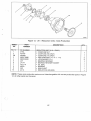
REDUCTION UNIT ASSEMBLY (1.523:1)
. HEX HEAD BOLT 1z¡u-'14 x 1-31¿)
. LOCKWASHEn g¡u¡
. HEX HEAD BOLT 1s¡"-18 x 1-1le)
. LOCKWASHEn
. COUPLING NUT
. COUPLING
. SNAP RING
. PINION CARRIER ASSEMBLY
. . OIL COLLECTOR RING
. . PINION SHAFT PIN
. . PINION SHAFT
. . PINION THRUSTWASHER
. . PINION BEARING SPACER
. . ROLLER BEARING
. . PINION GEAR
. . PINION CAGE
. LOCK BOLT 1z¡u-14 x 7le)
. SUN GEAR HUB
. SNAP RING
. SUN GEAR
SHAFT
". MAIN
BEARING ASSEMBLY
. . BEARING CONE. .
. . BEARING CUP
. SOLID SPACER (.820-.821 INCH LONG)..
. SOLID SPACER (.829-.830 INCH LONG)..
. SOLID SPACER (.832-.833 INCH LONG)..
. SOLID SPACER (.835-.836 INCH LONG)..
. SOLID SPACER (.838-.839 INCH LONG)..
. SOLID SPACER (.841-.842|NCH LONG)..
. SOLID SPACER (.844-.845 INCH LONG)..
. SOLID SPACER (.847-.848|NCH LONG)..
. SOLID SPACER (.850-.851 INCH LONG)..
. SOLID SPACER (.853-.854 INCH LONG)..
. SOLID SPACER (.856-.857 INCH LONG)..
. OIL SEAL
. BEARING ASSEMBLY
. . BEARING CONE .
. . BEARING CUP .
. REDUCTION HOUSING
. REAR ADAPTER GASKET
. LOCK BOLT (z¡u-14 x 7la)
. LOCKWASHER (4ro)
. REDUCTION UNIT ADAPTER
. SNAP RING
. BEARING
. SNAP RING
. INPUT GEAR
. RING GEAR
. FRONTADAPTER GASKEÏ
2
2
b
6
1s7u¡
t
1
1
1
1
1
3
3
6
I
144
3
1
4
1
1
1
1
1
1
1
'1
1
1
1
1
1
1
,
1
1
1
'1
1
1
1
1
1
".
1
6
6
1
1
'l
1
1
1
1
- REPLACE
**
BOTH PARTS IF ONE IS DAMAGED.
SELECT CORRECT SIZE SPACER AT ASSEMBLY. ONLY ONE REQUIRED.
û
46
Figure 11. 1.523:1 Reduction Units - Early Production
FtG.
11
NO NUMBER
1
4775L
2
45474Y
28
3
4
4547B.4
00001 79860
00001 03322
5
L4-7
6
7
L4-147
71C-110
I
I
DESCRIPTION
PART
NUMBER
INDEX
NO.
49204
L9-2
10
L4-4
11
4808
12
13
L4-151
1 03891
14
L4-1 A
REDUCTION UNIT
. COUPLING NUT
.
.
.
.
.
.
.
.
.
.
.
.
.
.
1
COUPLING(72CONLY)
COUPLING (71C ONLY)
HEX HEAD BOLT 1z¡u-14
LOCKWASHER (4ro)
QTY
1
1
x
1rl+)
BEARING RETAINER
BEARING RETAINER GASKET
OIL SEAL
BEARING
MAIN SHAFT
SUN GEAR
6
6
1
1
1
1
1
1
SPRING PIN
1
PINION CAGE DRIVE PIN
EXPANSION PLUG
REDUCTION HOUSING
1
1
1
NOTE: These early production parts are not interchangeable with current production parts in Figure
10. All other parts are the same.
47
1.88:1 AND 1.91 :1 REDUCTION UNITS
A.
CAUTION: Threaded plugs, screws,
DESCRIPTION
bolts, and coupling nut must
The 1.88:1 and 1.91:1 reduction units are
be I
tightened to torque shown in Table 4
to prevent premature reduction unit
failure.
mounted on the back of a 71C or 72C transmission. The reduction unit output shaft rotates the
opposite direction of the input shaft on the transmission. The output shaft rotates about one turn
for every two turns of the input shaft. Lubricating
oil is supplied to the reduction unit through ports
on the back of the transmission.
.
.
A new coupling nut must be used at assembly.
NOTE: For inspection, maintenance, and
Do not disassemble the pinion carrier assembly unless damaged. The necessary tools must
be available for proper assembly. Use exploded
view, Figure 12, for disassembly and assembly.
troubleshooting refer to the Table of Contents at
the front of this manual.
.
B.
The bearing cup and cone are a matched set.
lf one is damaged both must be replaced.
OVERHAUL
.
A solid spacer is used to control rolling torque
(end play). Rolling torque must be checked after
assembly of the reduction unit, before assembly
to the transmission.
The general overhaul information described on
page 12 applies to these reduction units. Before
starting disassembly, review the exploded-view
shown in Figure 12. The reduction unit can be
disassembled following the index numbers in
Figure 12. The following procedures are correct
for most reduction units. Minor differences may
be found.
NOTE: Early 1.91:1 reduction units used a collapsible spacer. lf this spacer must be replaced
use the solid spacer.
NOTE: Early 1.91:1 reduction units used a bearing retainer on the output shaft end of reduction
NOTE: Current Production 1.91:1 reduction units
use a reduction unit adapter (39), lock plates (23),
t
housing. To order correct parts refer to explodedview, Figure 13.
pinion carrier gasket (33), and o-ring (35) for
noise reduction.
t
48
STEP 1, lf removed, press bearing cone (11)on
to main shaft (8).
Bearing Cone Assembly
STEP 2. lnstall main shaft (8) in ring gear (9). lnstall snap ring (7) in groove of ring gear (9).
Main Shaft Assembly
STEP 3. lf removed, press bearing cups (12 and
17) into reduction housing (18).
Bearing Cup Assembly
49
STEP 4. lnstall main shaft (8)and ring gear (9) in
reduction housing (1 8).
BEARING
MAIN
SHAFT
CONE
I
Support ring gear (9). lnstall original spacer (13)
and'bearing c-one (16) in reduction housing (18)'
REDUCTION
HOUSING
CAUTION: lf original sPacer is not
used the replacement spacer should
be the same length. Using an incorrect size spacer can result in premature failure of reduction unit.
Spacer and Bearing Cone AssemblY
STEP 5. Place reduction housing (18) in press
with ring gear (9) supported. Press bearing cone
(16) on mãin shaft (8). Remove reduction housing
(18) from press.
BEARING
CONE
REDUCTION
HOUS¡NG
Bearing Cone AssemblY
STEP 6. lnstall oil seal (14) in reduction housing
(18). Outer surface of oil seal (14) should be flush
with reduction housing (18) face.
)
REDUCTION
HOUSING
Oil Seal AssemblY
I
50
STEP 7. Slide coupling (6) on main shaft (8).
Thread nut (5) on main shaft (8). Tighten nut (5)
to torque shown in Table 4.
COUPLING
COUPLING
NUT
REDUCTION
HOUSING
Attach a torque wrench to nut (5). Turn torque
wrench to check rolling torque of bearings (11
and 16). Rolling torque should be 5 to 30 in-lbs.
lf rolling torque is over 30 in-lbs replace spacer
(13)with a longer one. lf rolling torque is under 5
in-lbs replace spacer (13) with a shorter one.
127934
Coupling Assembly
NOTE: Selection of the proper spacer (13) will
result in 0 to 0.005 inch end play.
STEP 8. lf removed, install bearing (41) and
snap ring (40) in transmission.
SNAP
Lubricate front adapter gasket (a2) with vasoline
and install on transmission.
Front Adapter Gasket lnstallation
STEP
9. lnstall reduction unit adapter (39)
on
transmission.
Thread six bolts (37) with lockwashers (38) into
transmission. Tighten bolts (37) in a criss-cross
pattern to torque shown in Table 4.
i
__!
Reduction Unit Adapter Installation
51
STEP 10. For the 1.91:1 reduction unit do the
following:
GAUTION: The o-ring can only be in-
stalled on a reduction unit adapter
with the hub turned down. For complete details refer to Borg Warner
Automotive Service Bulletin M862.
c
Lubricate o-ring (35) with vasoline and install on
center hub of reduction unit adapter (39).
Lube Oil Strainer lnstallation
NOTE: Be sure o-ring (35) is not twisted, cut, or
distorted. Replace if damaged.
lnstall lube oil strainer (34) on reduction unit
adapter (39).
STEP 11. Place pinion carrier gasket (33) on
lube oil strainer (34).
I
Pinion Carrier Gasket lnstallation.
STEP 12. lnstall pinion carrier (24) on pinion carrier gasket (33) and align bolt holes.
For 1.91:1 reduction units install three lockplates
(23) and thread six bolts (21) into reduction unit
adapter (39) until finger tight.
For 1.88:1 reduction units thread six bolts (21)
with lockwashers (22) into reduction unit adapter
(39) until finger tight.
a-)
Slide sun gear (25) partially into pinion carrier
Pinion Carrier lnstallation
(24). Turn sun gear (25) by hand to be sure pinion
carrier (24)is centered and pinion gears (31)turn
freely.
I
52
STEP 13. Tighten six bolts (21) in a criss-cross
pattern to torque shown in Table 4.
CAUTION: For 1.91:1 reduction
units bolts are torqued to 5 ft-lbs.
Tabs on lockplates must be bent
tightly against flats of bolts.
Push sun gear (20) into pinion carrier (24). lnstall
snap ring (19) in groove of transmission output
shaft.
Sun Gear lnstallation
STEP 14. Lubricate rear adapter gasket (36)
with vasoline and install on reduction unit
adapter (39).
Rear Adapter Gasket lnstallation
STEP 15. Place reduction housing (18) on transmission. Turn coupling (6)to engage ring gear (9)
with pinion gears (31).
LOCKWASHER
Thread two bolts (1) with lockwashers (2) into
transmission.
Thread six bolts (3) with lockwashers (4) into reduction housing (18).
Tighten bolts (1 and 3) in a criss-cross pattern to
torque shown in Table 4.
Reduction Housing lnstallation
53
I
I
Figure 12. 1.88:1 and 1.91:1 Reduction units - current production
t
54
FtG. 12
NO NUMBER
NO NUMBER
00001 798ô4
00001 03322
00001 79840
124
1
2
3
4
00001 03321
5
6
10-00-031-001
10-00-149-034
7
4756D
10-17-171-002
I
-rF
10-17-171-OO4
L3-6
10-17-162-001
9
9A
10
2
2
6
6
. COUPLING 5,
. SNAP RING
. MAIN SHAFT (1.91:1 ONLy)
. MAIN SHAFT (1.88:1 ONLy)
. RING GEAR (1.91:1 ONLY)
. RING GEAR (1.88:1 ONLY)
. BEARING ASSEMBLY
. . BEARING CONE .
. . BEARING CUP .
1
1
1
1
1
1
1
13C
13D
13E
13F
13G
13H
NO NUMBER
10-00-133-010
10-00-133-009
10-1 7-053-002
10-17-053-003
10-17-053-004
10-17-053-005
10-17-053-006
10-1 7-053-007
1 0-1 7-053-008
10-17-053-009
10-17-053-010
13t
10-17-053-011
1
13J
10-17-053-012
10-00-044-017
NO NUMBER
1 0-00-1 33-002
1
11
12
13
134
138
14
15
16
17
18
19
10-00-133-001
204
7-065-003
4734
L7-104
10-17-165-004
21
48538
22
23
24
00001 1 4605
20
244
25
26
-
REDUCTION UNIT ASSEMBLy (1.91:1)
REDUCTION UNIT ASSEMBLy (1.88:1)
. HEX HEAD BOtt 1z¡u-14 x l-sl¿)
. LOCKWASHER 1z¡u¡
HEX HEAD BOLT
x 1-1le)
.' LOCKWASHEn 1s7"¡1s¡t-18
. COUPLING NUT
1
0-1
10-00-014-002
Lg-A150
10-17-659-021
4827
4717L
" REPLACE BOTH PARTS
- SELECT CORRECT
1
1
1
1
1
1
1
1
1
1
1
1
. BEARING ASSEMBLY
. . BEARING CONE .
o . BEARING CUp .
. REDUCTION HOUSTNG
. SNAP RING
. SUN GEAR (1.91:1 ONLY)
. SUN GEAR (1.88:1 ONLY)
. LOCK BOtt 1s¡u-18 x 3/a)
. LOCKWASHER (s/re) (1.88:1 ONLy)
. LOCK PLATE (1.91:1 ONLY)
. PINION CARRIER ASSEMBLY (1.91:1 ONLY)
. PINION CARRIER ASSEMBLY (1.88:1 ONLY)
. ¡ RETAINING R|NG
. . PINION SHAFT ptN
IF ONE IS DAMAGED.
SIZE SPACER AT ASSEMBLY. ONLY ONE REQUIRED.
55
1
1
1
1
1
1
1
1
6
6
3
1
1
1
6
INDEX
PART
NO.
NUMBER
27
DESCRIPTION
.
.
.
.
.
¡
¡
.
.
.
394
10-17-172-001
PINION SHAFT
PINION THRUSTWASHER
ROLLER BEARING (1.91:1 ONLY)
ROLLER BEARING (1.88:1 ONLY)
PINION BEARING SPACER (1.91:1 ONLY)
PINION BEARING SPACER (1.88:1 ONLY)
PINION GEAR (1.91:1 ONLY)
PINION GEAR (1.88:1 ONLY)
PLANETARY CAGE (1.91:1 ONLY)
PLANETARY CAGE (1.88:1 ONLY)
PINION CARRIER GASKET (1.91:1 ONLY)
LUBE OIL STRAINER (1.9'1:1 ONLY)
O-RING (1.91:1 ONLY)
REAR ADAPTER GASKET
LOCK BOLT 1z¡u-14 x 7la)
LOCKWASHER (7ro)
REDUCTION UNIT ADAPTER - - REDUCTION UNIT ADAPTER ****
4A
481 6
SNAP RING
41
B30SAGS
42
L4-145
BEARING
FRONT ADAPTER GASKET
L5-39
L3-43
28
29
47414
294
10-00-131-01
30
L3-4'1
304
1
31
314
32
324
33
34
35
36
1
0-00-053-024
L4-5
10-17-131-01 1
L9-1 50
10-17-159-011
10-17-045-001
L9-99
1
0-00-1 41-149
L4-146
37
0-00-1 83-073
00001 03322
1
38
39
L9.84
-
OTY
6
12
288
288
(.
6
18
6
6
1
1
1
'l
1
1
6
b
1
1
1
1
1
REPLACE BOTH PARTS IF ONE IS DAMAGED.
- SELECT CORRECT SIZE SPACER AT ASSEMBLY. ONLY ONE REQUIRED.
***
FOR USE WITH 1.91:1 NOISE REDUCTION PARTS. THESE INCLUDE
-
****
LOCK eLATES (29),
PrNtoN cARRtER GASKET (33), AND O-R|NG (35).
FOR USE WITH 1.88:1 OR 1.91:1 WITHOUT NOISE REDUCTTON PARTS
Ð
I
56
Figure 13. 1.91:1 Reduction Units - Early Production
INDEX
NO.
PART
NUMBER
FtG. 13
NO NUMBER
1
4775L
2
45474Y
28
4547B,A
00001 79860
3
4
5
6
7
I
9
10
00001 03322
L4-7
L4-147
71C-110
49204
L9-2
L5-1A
DESCRIPTION
REDUCTION UNIT (1.91:1 ONLY)
. COUPLING NUT
. COUPLINc (72C ONLY)
. COUPLING (71C ONLY)
. HEX HEAD BOLT 1z¡u-14 x 1-11¿)
. LOCKWASHER (4ro)
o BEARING RETAINER
o BEARING RETAINER GASKET
. OIL SEAL
. BEARING
. MAIN SHAFT
. REDUCTION HOUSING
QTY
1
1
1
6
6
1
1
1
1
1
1
NOTE: These early production parts are not interchangeable with current production parts in Figure
12. All other parts are the same.
57
2.57:1 AND 2.91=1 REDUCTION UNITS
A. DESCRIPTION
CAUTION: Threaded plugs, screws,
The 2.57:1 and 2.91:1 reduction units are
tightened to torque shown in Table 4
to prevent premature reduction unit
failure.
bolts, and coupling nut must be Ê
\*-
mounted on the back of a 71C or 72C transmission. The reduction unit output shaft rotates the
same direction as the input shaft on the transmission. The output shaft rotates about one turn for
every two and one half to three turns of the input
shaft. Lubricating oil is supplied to the reduction
unit through ports on the back of the transmis-
.
.
A new coupling nut must be used at assembly.
NOTE: For inspection, maintenance, and
Do not disassemble the pinion cage and output shaft assembly unless damaged. The necessary tools must be available for proper assembly.
Use exploded view, Figure 14, Íor disassembly
and assembly.
troubleshooting refer to the Table of Contents at
the front of this manual.
.
sion.
B.
The bearing cup and cone are a matched set.
lf one is damaged both must be replaced.
OVERHAUL
o A solid spacer is used to control rolling torque
(end play). Rolling torque must be checked after
assembly of the reduction unit, before assembly
to the transmission,
The general overhaul information described on
page 12 applies to these reduction units. Before
starting disassembly, review the exploded-view
shown in Figure 14. The reduction unit can be
disassembled following the index numbers in
Figure 14. The following procedures are correct
for most reduction units. Minor differences may
NOTE: Early reduction units used a collapsible
spacer. lf this spacer must be replaced use the
solid spacer.
be found.
NOTE: Early reduction units used a bearing retainer on the output shaft end of the reduction
t
housing. To order correct parts refer to explodedview, Figure 15.
I
58
STEP 1. lf removed, press bearing cone (17) on
pinion cage and output shaft (7).
Bearing Cone Assembly
.
STEP 2. lf removed, press bearing cups (19 and
23) into reduction housing (26).
Bearing Cup Assembly
STEP 3. Place oil baffle (25) in reduction housing (26). Thread two bolts (24) into reduction
housing (26). Tighten bolts (24)to torque shown
in Table 4.
Oil Baffle lnstallation
59
STEP 4. lnstall pinion cage and output shaft (7)
in reduction housing (26).
BEARING
CONE
Support pinion cage and output shaft (7). lnstall
original spacer (19) and bearing cone (22) in reduction housing (26).
û
CAUTION: lf original spacer is not
used the replacement spacer should
be the same length. Using an incorrect size spacer can result in premature failure of reduction unit.
Spacer and Bearing Cone Assembly
STEP 5. Place reduction housing (26) in press
with pinion cage and output shatt (7) supported.
Press bearing cone (22) on pinion cage and output shaft (7). Remove reduction housing (26)
from press.
BEARING
REDUCTION
HOUSING
'127914
Bearing Cone Assembly
STEP 6. lnstall oil seal (20) in reduction housing
(26). Outer surface of oil seal (20)should be flush
with face of reduction housing (26).
t
REDUCTION
HOUSING
t,(
ö-t
(
Oil Seal Assembly
I
60
STEP 7. Slide coupling (6) on pinion cage and
output shaft (7). Thread nut (S) on pinion cage
arrd output shaft (7). Tighten nut (5) to torque
shown in Table 4.
Attach a torque wrench to nut (S). Turn torque
wrench to check rolling torque of bearings (17
and 22). Rolling torque should be 5 to 30 in-lbs.
lf rolling torque is over 30 in-lbs replace spacer
(13) with a longer one. lf rolling torque is r.¡nder
in-lbs replace spacer (13) rruith a shorter one.
S
Coupling Assembly
NOTE: Selection of the proper spacer (1g) will
result in 0 to 0.005 inch end play.
STEP 8. lf removed, install bearing (37) and
snap ring (36) in transmissi<¡n.
SNAP
Lubricate front adapter gasket (38) with vasoline
and install on transmission.
Front Adapter Gasket lr¡stallation
STEP 9. lnstall stationary gear plate (32) in ring
gear (33). lnstall snap ring (31) in groove of ring
gear (33).
STATIONARY
GEAR PLATE
Stationary Gear Plate Assembly
61
STEP 10. lnstall reduction unit adapter (35) and
ring gear (33) on transmission.
REDUCTION
UNIT
ADAPTER
Thread six bolts (29) with lockwashers (30) into
transmission. Tighten bolts (29) in a criss_cross
pattern to torque shown in Table 4.
RING
GEAR
Ð
LOCK
WASHER
BOLT
iì
'12809A
Reduction Unit Adapter lnstallation
STEP 11. Slide sun gear (2g) on transmission
output shaft.
SUN GEAR
lnstall snap ring (27) in groove of output shaft.
Sun Gear Installation
Ð
STEP 12. Lubricate rear adapter gasket (34)
with vasoline and install on reduction unii
adapter (gS).
Rear Adapter Gasket lnstallation
e
62
STEP 13. Place reduction housing (26) on trans_
mission. Turn coupling (6)to engagL'pinion gears
(1a)with ring gear (03).
Thread two bolts (1) with lockwashers (2) into
transmission.
Thre.ad six bolts (3) with lockwashers (4) into
duction housing (18).
re_
Tighten bolts (1 and 3) in a criss_cross pattern
to
torque shown in Table 4.
'128014
Reduction Housing lnstallation
63
Ð
k
s
Figure 14.2.57:1and 2.91:1 Reduction Units - Current production
e
64
INDEX
NO.
PART
NUMBER
DESCRIPTION
FIG. 14
NO NUMBER
NO NUMBER
00001 79864
00001 03322
00001 79840
REDUCTION UNIT ASSEMBLY (2.S7:1)
REDUCTION UNIT ASSEMBLY(2.91 :1 )
. HEX HEAD BOLT 1z¡u-14 x 1-31¿)
. LOCKWASHER (4ro)
' HEX HEAD BOLT (s¡"-16 x 1-1le)
144
1
2
3
4
00001 03321
5
10-00-149-034
6
7
10-00-031-001
7A
I
8A
o
9A
10
11
114
12
13
14
1
1
7-659-007
.
.
.
.
0-1 7-659-008
¡
0-1
L6-1 35
L4-1 35
R108-40
47178
L5-39
L6-43
L3-43
4741 A
L3-41
144
L6-5
L4-5
15
1
154
16
17
194
198
19C
19D
19E
19F
19G
19H
19r
19J
21
-
--
NO NUMBER
10-00-133-010
.
.
.
.
.
.
.
.
.
.
.
.
.
.
10-'17-053-004
10-17-053-005
1 0-1 7-053-006
1 0-1 7-053-007
1 0-1 7-053-008
10-1 7-053-009
10-17-053-010
10-17-053-01
1
10-17-053-012
10-00-044-017
NO NUMBER
1
COUPLING
PINION CAGE AND OUTPUT SHAFT
ASSEMBLY (2.57:1ONLY)
PINION CAGE AND OUTPUT SHAFT
ASSEMBLY (2.91:1 ONLY)
. OIL COLLECTOR RING (2.57:1ONLY)
. OIL COLLECTOR RING (2.91:1 ONLY)
. PINION SHAFT PIN (2.57:1 ONLy)
. PINION SHAFT PIN (2.91:1 ONLy)
. PINION SHAFT
. THRUSTWASHER (2.57:1ONLY)
. THRUSTWASHER (2.91:1ONLy)
o ROLLER BEARING
. PINION BEARING SPACER
. PINION GEAR (2.57:l ONLY)
. PINION GEAR (2.91:1ONLY)
. PINION CAGE AND OUTPUT SHAFT
. .
10-17-053-002
1 0-1 7-053-003
2
2
6
6
LOCKWASHEn 1s7u¡
COUPLING NUT
10-17-159-004
'10-00-133-009
18
19
20
0-1 7-1 59-003
.
.
.
.
.
.
.
.
.
.
.
.
QTY
1
1
1
1
1
6
6
6
12
12
288
6
6
6
1
(2.57:1ONLY)
PINION CAGE AruO OUTpUT SHAFT
(2.91:1 ONLY)
BEARING ASSEMBLY . BEARING CONE .
. BEARING CUP .
SOLID SPACER (.820-.s2i |NCH LONG)
SOLID SPACER (.829-.830 |NCH LONG)
soltD spAcER (.832-.833 INCH LONG)
SOLID SPACER (.835-.836 |NCH LONG)
soltD spAcER (.838-.839 |NCH LONG)
soltD spAcER (.841-.842 |NCH LONG)
SOLID SPACER (.844-.B4s INCH LONG)
SOLID SPACER (.847-.B4B |NCH LONG)
SOLID SPACER (.850-.8s1 |NCH LONG)
SOLID SPACER (.8s3-.8s4 |NCH LONG)
SOLID SPACER (.8s6-.8S7 |NCH LONG)
OIL SEAL
BEARING ASSEMBLY
1
1
1
1
1
1
1
1
1
1
1
1
1
1
,
REPLACE BOTH PARTS IF ONE IS DAMAGED.
SELECT CORRECT SIZE SPACER AT ASSEMBLY. ONLY ONE REQUIRED.
65
1
1
1
INDEX
10-00-133-002
22
23
24
25
26
27
28
10-00-133-001
477688
10-17-036-001
10-17-065-001
4734
L6-1 04
284
29
30
DESCRIPTION
PART
NUMBER
NO.
L7-104
4853E
.
.
BEARING CONE BEARING CUP LOCK BOLT ('z/ro-'14 x 7la)
OIL BAFFLE
REDUCTION HOUSING
SNAP RING
SUN GEAR (2.57:1ONLY)
SUN GEAR (2.91:1ONLY)
LOCK BOLT 1z¡u-14 x 1rl+)
00001 1 5550
LOCKWASHER 1z¡u¡
31
47568
314
4756D
32
L6-31
324
t7-31
33
L3-6
L6-6
SNAP RING (2.57:1 ONLY)
SNAP RING (2.91:1 ONLY)
STATIONARY GEAR PLATE (2.57 :1 ONLY)
SïATIONARY GEAR PLATE (2.91:1 ONLY)
RING GEAR (2.57:1ONLY)
334
34
35
36
37
38
-
L4-146
L7-84
481 6
B3OSAGS
L4-145
RING GEAR (2.91:1 ONLY)
REAR ADAPTER GASKET
REDUCTION UNIT ADAPTER
SNAP RING
BEARING
FRONT ADAPTER GASKET
QTY
1
1
2
t
1
1
1
1
1
6
6
1
1
1
1
1
1
,1
1
1
1
1
REPLACE BOTH PARTS IF ONE IS DAMAGED,
- SELECT CORRECT SIZE SPACER AT ASSEMBLY. ONLY ONE REQUIRED.
Ð
e
66
.Kìz
Figure 15. 2.57=1 AND 2.91:1 Reduction Units - Early Production
INDEX
PART
NO.
NUMBER
FlG. 15
2
3
4
NO NUMBER
NO NUMBER
10-00-1 49-002
4912
00001 79860
00001 03322
5
6
L4-147
7
71C-1 10
9
4920
L6.A3D
9A
L7-A3D
154
1
I
10
L4-7
L7-14
DESCRIPTION
REDUCTION UNIT (2.57:1 ONLY)
REDUCTION UNIT (2.91:1 ONLY)
. COUPLING NUT
. COUPLING
. HEX HEAD BOLT (?ro-14 x 1rl¿)
. LOCKWASHEn 1z¡u¡
. BEARING RETAINER
. BEARING RETAINER GASKET
. OIL SEAL
o BEARING
. PINION CAGE AND OUTPUT SHAFT
ASSEMBLY (2.57:1ONLY)
. PINION CAGE AND OUTPUT SHAFT
ASSEMBLY (2.91:1 ONLY)
. REDUCTION HOUSING
QTY
1
1
6
b
1
1
1
1
'l
1
1
NOTE: These early production parts are not interchangeable with current production parts in Figure
14. All other parts are the same.
67
2.10:1 REDUCT¡ON UNIT
i--;l
i /f\ i
LLli i
A. DESCRIPTION
The 2.10:1 reduction unit is mounted on the back
of a71C or 72C transmission. The reduction unit
output shaft rotates the same direction as the input shaft on the transmission. The output shaft
rotates about one turn for every two turns of the
input shaft. Lubricating oil is supplied to the reduction unit through ports on the back of the
transmission.
o A new coupling nut must be used at assembly.
.
Do not disassemble the pinion carrier assembly unless damaged. The necessary tools must
be available for proper assembly. Use the exploded view, Figure 16, for disassembly and as-
NOTE: For inspection, maintenance, and
troubleshooting refer to the Table of Contents at
the front of this manual.
B.
CAUTION: Threaded plugs, screws,
bolts, and coupling nut must be
tightened to torque shown in Table 4
to prevent premature reduction unit
failure.
sembly.
.
The bearing cup and cone are a matched set.
lf one is damaged both must be replaced.
OVERHAUL
.
A solid spacer is used to control rolling torque
(end play). Rolling torque must be checked after
assembly of the reduction unit, before assembly
to the transmission.
The general overhaul information described on
page 12 applies to these reduction units. Before
starting disassembly, review the exploded-view
shown in Figure 16. The reduction unit can be
disassembled following the index numbers in
Figure 16. The following procedures are correct
for most reduction units. Minor differences may
NOTE: Early reduction units used a collapsible
spacer. lf this spacer must be replaced use the
solid spacer.
be found.
Ð
NOTE: Early reduction units used a bearing retainer on the output shaft end of reduction housing. To order correct parts refer to exploded-view,
Figure 17.
þ
68
STEP 1. lf removed, press bearing cone (12) on
output shaft (8).
Bearing Cone Assembly
STEP 2. lf removed, install bushing (9) in output
shaft (8).
lnstall output shaft (8) in ring gear (9). lnstall snap
ring (7) in groove of ring gear (10).
Output Shaft Assembly
STEP 3. lf removed, press bearing cups (13 and
18) into reduction housing (20).
BEARING CUP
Bearing Cup Assembly
69
STEP
4.
lnstall output shaft (8) and ring gear
(10) in reduction housing (20).
MAIN
SHAFT
BEARING
CONE
Turn reduction housing (20) over and install origi-
nal spacer (14) and bearing cone (17) in reduction housing (20).
CAUTION: lf original spacer is not
used the replacement spacer should
be the same length. Using an incorrect size spacer can result in premature failure of reduction unit.
REDUCTION
HOUSING
Spacer and Bearing Cone Assembly
STEP 5. Place reduction housing (20) in press
with ring gear (10) supported. Press bearing
BEARING
CONE
cone (17) on output shaft (8). Remove reduction
housing (20) from press.
REDUCTION
HOUSING
12791À
Bearing Cone Assembly
STEP
6.
e
lnstall oil seal (15) in reduction housing
(20). Outer surface of oil seal (15) should be flush
with reduction housing (20) face.
REDUCTION
HOUSING
Oil Seal Assembly
@r
70
STEP 7. Slide coupling (6) on output shafr (B),
Thread nut (5) on output shaft (B). Tighten nut (5)
to torque shown in Table 4.
Attach a torque wrench to nut (S). Turn torque
wrench to check rolling torque of bearings (12
and 17). Rolling torque should be 5 to 30 in-lbs.
COUPLING
COUPLING
NUT
REDUCTION
HOUSING
lf rolling torque is over 30 in-lbs replace spacer
(14) with a longer one. lf rolling torque is under
in-lbs replace spacer (14) with a shorter one.
NOTE: Selection of the proper spacer (1a)
result in 0 to 0.005 inch end play,
S
12793A
wiil
Coupling Assembly
STEP 8. Lubricate front adapter gasket (43)with
vasoline and install on transmission.
Front Adapter Gasket lnstallation
STEP 9. Slide sun gear (41) into reduction unit
adapter (42).
REDUCTION
UNIT ADAPTER
Turn reduction unit adapter (42) over.lnstall snap
ring (40) in groove of sun gear (41).
@(w
o\
r@
Sun Gear Assembly
71
STEP 10. lnstall reduction unit adapter (42) on
transmission.
REDUCTION UNIT ADAPTER
Thread six bolts (38) with lockwashers (39) into
transmission. Tighten bolts (38) ìn a criss-cross
pattern to torque shown in Table 4.
irl
l
--j
Reduction Unit Adapter lnstallation
STEP 11. Lubricate one thrustwasher (21) with
vasoline and install on sun gear (41).
irl
Ll:
Thrustwasher lnstallation
STEP 12. Slide pinion cage assembly (22) on
transmission output shaft.
Lubricate thrustwasher (21) with vasoline and install on pinion cage assembly (22).
Pinion Cage lnstallation
72
Ð
STEP 13. Lubricate rear adapter gasket (37)
with vasoline and install on reduction unit
adapïer (42).
Rear Adapter Gasket lnstallation
STEP 14. Place reduction housing (20) on transmission. Turn coupling (6) to engage ring gear
(10) with pinion gears (29 and 35).
LOCKWASHER
w/ò
r((
Thread two bolts (1) with lockwashers (2) into
transmission.
l-,
' I
t
Thread six bolts (3) with lockwashers (4) into reduction housing (20).
Tighten bolts (1 and 3) in a criss-cross pattern to
torque shown in Table 4.
1280't
Reduction Housing lnstallation
73
A
37
{.
t
Figure 16.2.10:1 Reduction Units - Current production
€
74
r-
PART
NUMBER
INDEX
NO.
FlG. 16
NO NUMBER
00001 79864
00001 03322
00001 79840
00001 03321
1 0-00-1 49-034
1
2
3
4
5
6
10-00-031-001
7
4756D
8
10-17-671-001
I
A4867DD
10
L3-6
11
14G
14H
NO NUMBER
10-00-133-010
10-00-133-009
1 0-1 7-053-002
1 0-1 7-053-003
1 0-1 7-053-004
10-17-053-005
1 0-1 7-053-006
1 0-1 7-053-007
1 0-1 7-053-008
10-17-053-009
10-17-053-010
14r
10-17-053-01
14J
10-17-053-012
10-00-044-017
NO NUMBER
1 0-00-1 33-002
12
13
14
144
148
14C
14D
148
14F
15
16
17
'18
1
10-00-133-001
'10-00-191-002
19
20
21
22
224
23
24
25
26
27
28
10-17-065-002
13-24
10-17-659-006
10-17-659-010
L4-1 35
4717L
L5-394
72-43
47414
L3-41
DESCRIPTION
REDUCTION UNIT ASSEMBLY(2.1 0:
. HEX HEAD BOLT (z¡u-14 x 1-31+)
. LOCKWASHER (4ro)
. HEX HEAD BOLT 1s¡u-16 x 1-1la)
. LOCKWASHEn 1s¡u¡
. COUPLING NUT
. COUPLING
.
.
.
.
.
.
.
.
.
.
.
.
.
.
.
.
.
.
.
.
.
.
.
.
.
.
.
.
¡
¡
o
.
o
****
)
2
2
6
6
1
1
SNAP RING
OUTPUT SHAFT AND BUSHING ASSEMBLY
.
BUSHING (KlT)
RING GEAR
BEARING ASSEMBLY
. BEARING CONE . BEARING CUP .
SOLID SPACER (.820-.821lNCH
soltD SPACER (.829-.830 INCH
SOLID SPACER (.832-.833 INCH
SOLID SPACER (.835-.836 INCH
soLtD SPACER (.838-.839 INCH
SOLID SPACER (.841-.842|NCH
SOLID SPACER (.844-.845lNCH
SOLID SPACER (.847-.848INCH
SOLID SPACER (,850-.851 INCH
SOLID SPACER (.853-.854 INCH
SOLID SPACER (.856-.857 INCH
OIL SEAL
BEARING ASSEMBLY
. BEARING CONE .
. BEARING CUP .
PLASTIC PLUG
REDUCTION HOUSING
THRUSTWASHER
PINION CAGE ASSEMBLY...
PINION CAGE ASSEMBLY ****
. OIL COLLECTOR RING
o PINION SHAFT PIN
o PINION SHAFT
o PINION THRUST PLATE
. ROLLER BEARING
¡ PINION BEARING SPACER
- REPLACE BOTH PARTS IF ONE IS DAMAGED.
** SELECT CORRECT SIZE SPACER AT ASSEMBLY.
**"
1
QTY
1
1
1
1
1
1
LONG)
LONG)
LONG)
LONG)
."
-.
."
..
LONG)..
LONG) ""
LONG)..
LONG)..
LONG)
LONG)
LONG)
..
..
..
1
1
1
1
1
1
1
1
1
1
1
1
1
1
1
1
1
1
2
1
1
1
4
4
4
192
4
ONLY ONE REQUIRED.
USED WITH TRANSMISSIONS 1O-17-OOO-OO9 AND 1O-18-OOO-007. HAS DRILL SPOTS ON
PLANETARY CAGE FOR IDENTIFICATION.
usED wtTH TRANSMTSSTONS 10-17-000-010 AND 10-18-000-008.
75
INDEX
PART
NO.
NUMBER
L3-1 05
29
30
R4-40
L5-39
72-43
31
32
33
34
35
36
L3-41
47414
L3-5
10-17-659-005
1 0-1 7-659-009
L4-146
1 0-00-1 83-073
1 1 5550
364
37
38
39
40
47664
10-17-165-002
L5-84
L4-145
41
42
43
-
.
.
.
.
.
.
.
.
.
.
.
.
.
.
.
.
DESCRIPTION
OTY
RH PINION GEAR
PINION SHAFT PIN
PINION SHAFT
PINION THRUST PLATE
PINION BEARING SPACER
ROLLER BEARING
LH PINION GEAR
PLANETARY CAGE ASSEMBLY PLANETARY CAGE ASSEMBLY
REAR ADAPTER GASKET
LOCK BOtt 1z¡u-14 x 7le)
LOCKWASHER (4ro)
4
4
4
4
.
.
.
.
.
.
.
.
.
SNAP RING
0
12
192
4
1
1
1
b
6
1
SUN GEAR
REDUCTION UNIT ADAPTER
FRONTADAPTER GASKET
1
'1
1
- REPLACE BOTH PARTS IF ONE IS DAMAGED.
- SELECT CORRECT SIZE SPACER AT ASSEMBLY.
***
****
ONLY ONE REQUIRED.
AND 1O-18-OOO-007. HAS DRILL SPOTS ON
USED WITH TRANSMISSIONS 1O-17-OOO-OO9
PLANETARY CAGE FOR IDENTIFICATION.
usED wtTH TRANSMISSIONS 10-17-000-010 AND 10-18-000-008,
)
(
76
/rr
Figure 17.2.10:1 Reduction Units - Early Production
INDEX
PART
NUMBER
NO.
FtG. 17
NO NUMBER
1
4775t
2
45474Y
28
454784
3
4
00001 79860
00001 03322
5
L4-7
6
7
L4-147
I
I
71C-1 10
49204
L5-43
10
L5-4
11
L5-1 B
DESCRIPTION
REDUCTION UNIT (2.1 0:1)
. COUPLING NUT
. COUPLING (72C ONLY)
. COUPLING (71C ONLY)
. HEX HEAD BOLT 1z¡u-14 x 1rl+)
. LOCKWASHEn 1z¡u¡
¡ BEARING RETAINER
. BEARING RETAINER GASKET
. OIL SEAL
. BEARING
. OUTPUT SHAFT AND BUSHING ASSEMBLY
. SUN GEAR
. REDUCTION HOUSING
OTY
1
1
1
6
6
1
1
1
1
1
1
1
NOTE: These early production parts are not interchangeable with current production parts in Figure
16. All other parts are the same.
77