1
B2
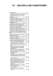
ENGINE MECHANICAL
3SZ --------------------------------------- B21
ENGINE ASSY ------------------------- B21
REMOVAL AND INSTALLATION(RHD
2WD VEHICLES)---------------------- B21
B2-1
3SZ
1 ENGINE ASSY
1-1 REMOVAL AND INSTALLATION(RHD 2WD VEHICLES)
WARNING
No fire should be brought near when servicing the fuel system.
When removing the fuel hose, prevent the fuel from splashing.
When the coolant is hot, do not remove the radiator cap, drain plug or water hose.
When the oil is hot, do not remove the drain plug or oil cooler hose.
1-1-1 ARTICLES TO BE PREPARED
Lubricant,adhesive,others
Engine hanger attaching bolt (Replacement parts),Wooden block,Three Bond1324
1-1-2 OPERATION BEFORE REMOVAL
1. Release the fuel pressure.
Refer to TERIOS SERVICE MANUAL
2. Remove the battery and the battery carrier.
Refer to TERIOS SERVICE MANUAL
3. Ensure that the disc wheels (FR) are in a position where the vehicle will move straight ahead.
4. Remove the disc wheel (FR).
Refer to TERIOS SERVICE MANUAL
5. Remove the engine under cover.
Refer to Page I2-1.
6. Drain the engine oil.
Refer to TERIOS SERVICE MANUAL
7. Drain the ATF. (A/T vehicles)
Refer to TERIOS SERVICE MANUAL
8. Drain the transmission oil. (M/T vehicles)
Refer to TERIOS SERVICE MANUAL
9. Drain the coolant.
Refer to TERIOS SERVICE MANUAL
10. Disconnect radiator hose No.1 and radiator hose No.2 from the radiator.
Refer to TERIOS SERVICE MANUAL
11. Disconnect water hose No.1 and water hose No.2 from the heater radiator Ay.
12. Remove the oil cooler hose. (A/T vehicles)
Refer to TERIOS SERVICE MANUAL
13. Remove the V-ribbed belt.
Refer to TERIOS SERVICE MANUAL
B2-2
14. Remove the compressor Ay, W/magnet clutch
Refer to Page K1-11.
NOTE
Without disconnecting the pipe, suspend it from the
body side, using a cord, etc.
15. Disconnect the vacuum hose Ay from the brake booster
Ay.
Refer to TERIOS SERVICE MANUAL
16. Remove the charcoal canister Ay.
Refer to Page B9-1.
17. Remove the air cleaner case S/A.
Refer to TERIOS SERVICE MANUAL
18. Disconnect the accelerator control cable Ay from the
throttle body Ay.
Refer to Page B3-1.
19. Remove the glove compartment door Ay.
Refer to TERIOS SERVICE MANUAL
20. Remove the front door scuff plate RH and the front door
scuff plate LH.
Refer to TERIOS SERVICE MANUAL
21. Remove the cowl side trim board RH and the cowl side
trim board LH.
Refer to TERIOS SERVICE MANUAL
22. Remove the No.1 instrument panel under cover.
Refer to Page I2-4.
23. Remove the No.2 instrument panel under cover.
Refer to Page I2-4.
24. Disconnect the engine wire from the transmission control computer Ay. (A/T vehicles)
Refer to TERIOS SERVICE MANUAL
25. Disconnect the engine wire from the fuel injection computer Ay, and pull out the wire on the engine compartment side.
Refer to TERIOS SERVICE MANUAL
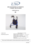
26. Disconnect the wire harness from the relay block located in the engine compartment.
P21E5559T10
B2-3
27. Disconnect the connectors and the wiring of each sensor and the earth wires.
NOTE
Disconnect the body earth of the battery from the body side.
28. Remove the steering intermediate shaft Ay.
CAUTION
Put matchmark on each shaft, and remove the shafts.
Refer to Page G1-2.
29. Remove the suspension LWR arms S/A W/bush RH/LH.
Refer to Page C1-5.
30. Remove the ball joint section of the tie rod end S/A.
Refer to Page D2-2.
31. Remove the FR stabilizer bar.
Refer to Page C1-9.
32. Remove the front exhaust pipe Ay.
Refer to Page B4-3.
33. Remove the propeller FR shaft Ay.
CAUTION
Put matchmark on the universal joint yoke and the differential flange, and remove them.
Refer to TERIOS SERVICE MANUAL
34. Disconnect the automatic transmission control cable Ay. (A/T vehicles)
Refer to TERIOS SERVICE MANUAL
35. Disconnect the manual transmission control cable Ay. (M/T vehicles)
Refer to TERIOS SERVICE MANUAL
36. Remove the clutch release cylinder Ay. (M/T vehicles)
Refer to TERIOS SERVICE MANUAL
37. Set the engine Ay W/transmission to the engine lifter.
NOTE
Set the engine Ay W/transmission to the engine lifter, with the FR suspension member Ay and the
RR engine support member Ay still attached.
Use wooden blocks, etc to support the engine Ay W/transmission Ay, in a well-balanced way.
38. Disconnect the fuel hose from the fuel delivery pipe Ay.
Refer to TERIOS SERVICE MANUAL
B2-4
1-1-3 REMOVAL AND INSTALLATION PROCEDURES
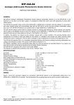
(1) Components
i
T:37.0&11.1 {377&113}
B
T:58.8&9.8 {600&99}
T:58.0&9.8 {599&99}
~B
e
T:37.0&11.1 {377&113}
B
T:8.8&0.9 {90&9}
N
a
T:48.1&13.7 {490&139}
B
B
d
B
N
N
g
T:18.0&5.4 {183&55}
B
T:36.8&7.3 {375&74}
h
B
B
f
T:78.0&4.7 {795&47}
T:27.5&4.9 {280&49}
T:36.8&7.3 {375&74}
b
B
c
B
T:39.0&7.8 {398&79}
T:110.0&22.0 {1122&224}
B
P22E5503ES40
:Non-reusable parts
:Equivalent to Three Bond1324
Unit:Nm{kgfcm}
Illust : Vehicles with Automatic transaxle Ay
B2-5
(2) Removal and installation procedures
1
2
3
4
5
a
b
c
d
e
Starter Ay
Member Ay, engine support, rear
Member Ay, FR suspension
Transaxle Ay, automatic
Converter Ay, torque
6
7
8
9
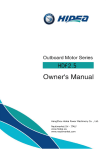
1-1-4 POINTS OF REMOVAL
(1) Engine Ay, Automatic transaxle Ay, RR engine support member Ay, FR suspension member Ay
1. Set the engine lifter at the position shown in the figure.
2. Use wooden blocks, etc to support the engine Ay
W/transmission Ay, in a well-balanced way.
NOTE
Put a wooden piece, etc. on the installation position of
the compressor Ay W/ magnet clutch on the left side of
the engine block Ay.
CAUTION
Do not apply wooden blocks to the crankshaft pulley.
3. Operate the engine lifter, and remove the engine Ay,
with the transmission Ay and the member still attached.
CAUTION
Perform the removal, making sure that no connectors
or hoses are still connected or coming into contact with
other parts.
Perform the removal in such a way that the part does
not come into contact with the components within the
engine compartment.
NOTE
In cases where an engine lifter is not used, move the
side of the vehicle (Two-post lift, etc.) up and down
during the operation.
4. Remove the transmission Ay.
M/T vehicles
Refer to Page F2-1.
f
g
h
i
Gear S/A, drive plate and ring
Bracket, engine mounting, FR RH
Bracket, engine mounting, FR No.2
Engine Ay
P22E5504T10
P22E5505T10
A/T vehicles
Refer to TERIOS SERVICE MANUAL
5. Install the support tools (engine hangers, etc.) in the positions indicated in the figure on the right.
6. Support the engine Ay using the chain block.
7. Remove the engine mounting FR RH insulator and the
engine mounting bracket FR RH.
Refer to Page B12-1.
8. Remove the engine mounting FR LH insulator and the
engine mounting bracket FR No.2.
Refer to Page B12-4.
P22C5806T10
B2-6
9. Suspend the engine Ay using the chain block.
CAUTION
Make sure that the engine Ay is supported in a well-balanced way during the removal.
10. Remove the guide S/A, oil level gauge and the engine mounting bracket FR RH.
11. Remove the engine mounting bracket FR RH.
12. Remove the engine mounting bracket FR No.2.
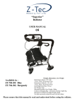
1-1-5 POINTS OF INSTALLATION
(1) Bracket, engine mounting, FR RH
3
1. Temporarily tighten the bolt .
2. Tighten the bolts securely, in the sequence
1
.
TIGHTENING TORQUE: 37.011.1Nm
2
4
{377113kgfcm}
P22E5506T10
3. Tighten the bolt indicated in the illustration, and install
the guide S/A, oil level gauge.
P22E5530T10
(2) Bracket, engine mounting, FR No.2
1. Temporarily tighten the bolt .
2. Tighten the bolts securely, in the sequence
.
TIGHTENING TORQUE: 18.05.4Nm
{18355kgfcm}
3
1
2
4
P22E5507T10
B2-7
(3) Gear,flywheel ring (M/T vehicles)
1. Clean off any adhesive adhered to the female threaded section of the crankshaft or the installation
surface of the flywheel ring gear.
2. Apply the looseness prevent agent on the threaded area.
ADHESIVE: Three Bond1324
3. Temporarily tighten the bolts.
4. Tighten the bolts in the sequence shown in the figure.
TIGHTENING TORQUE: 784.7Nm
{79548kgfcm}
1
3
6
5
4
2
P21E5599ET16
(4) Gear,S/A,drive plate & ring (A/T vehicles)
Refer to TERIOS SERVICE MANUAL
(5) Engine Ay, Automatic transaxle Ay, RR engine support member Ay, FR suspension member
Ay
1. Slowly lower the engine Ay, using the chain block, and then attach the insulators and the engine
brackets.
CAUTION
Make sure that the engine Ay is supported in a well-balanced way during the removal.
NOTE
Install the FR suspension member Ay, with the steering gear box and the power steering vane
pump Ay still attached.
2. Install the transmission Ay.
M/T vehicles
Refer to Page F2-1.
A/T vehicles
Refer to TERIOS SERVICE MANUAL
3. Support the engine Ay W/transmission and the FR suspension member, using the chain block.
B2-8
4. Set the engine lifter in the position indicated in the illustration.
NOTE
Set the engine Ay W/transmission to the engine lifter,
with the FR suspension member Ay and the RR engine support member Ay still attached.
Use wooden blocks, etc to support the engine Ay
W/transmission Ay, in a well-balanced way.
CAUTION
P22E5504T10
Do not place wooden blocks against the crankshaft
pulley Ay.
1-1-6 OPERATION AFTER INSTALLATION
1. Operate the engine lifter, and mount the engine Ay into the vehicle, with the transmission Ay still attached.
CAUTION
Perform the installation, making sure that no parts are coming into contact with other parts.
Perform the installation in such a way that it does not come into contact with the LWR suspension
arm S/A or components within the engine compartment.
NOTE
In cases where an engine lifter is not used, move the side of the vehicle (Two-post lift, etc.) up and
down during the operation.
2. Install the FR suspension member, and tighten the bolts to the specified torque.
Refer to Page C1-12.
3. Install the rear engine support member Ay, and tighten the bolts to the specified torque.
Refer to Page B12-6.
4. Connect the fuel hose to the fuel delivery pipe Ay.
Refer to TERIOS SERVICE MANUAL
5. Install the automatic transmission control cable Ay. (A/T vehicles)
Refer to TERIOS SERVICE MANUAL
6. Install the manual transmission control cable Ay. (M/T vehicles)
Refer to TERIOS SERVICE MANUAL
7. Install the clutch release cylinder Ay. (M/T vehicles)
Refer to TERIOS SERVICE MANUAL
8. Install the propeller FR shaft Ay.
Refer to TERIOS SERVICE MANUAL
CAUTION
Align the matchmark of the universal joint yoke and the differential flange, and attach them.
B2-9
9. Install the FR exhaust pipe Ay.
Refer to Page B4-3.
10. Install the FR stabilizer bar.
Refer to Page C1-9.
11. Install the ball joint section of the tie rod end S/A.
Refer to Page D2-2.
12. Install the suspension lower arms S/A W/bush RH/LH.
Refer to Page C1-5.
13. Install the steering intermediate shaft Ay.
Refer to Page G1-2.
CAUTION
Align the matchmark of each shaft, and attach the shafts.
14. Remove the support tools. (Engine hangers, etc.)
15. Connect the connectors and the wiring of each sensor
and the earth wires.
16. Install the wire harness to the relay block located in the
engine compartment.
17. Connect the engine wire to the fuel injection computer
Ay.
Refer to TERIOS SERVICE MANUAL
18. Connect the engine wire to the transmission control
computer Ay. (A/T vehicles)
Refer to TERIOS SERVICE MANUAL
19. Install the No.1 instrument panel under cover.
Refer to Page I2-4.
20. Install the No.2 instrument panel under cover.
Refer to Page I2-4.
21. Install the cowl side trim board RH and the cowl side
trim board LH.
Refer to TERIOS SERVICE MANUAL
22. Install the front door scuff plate RH and the front door
scuff plate LH.
Refer to TERIOS SERVICE MANUAL
23. Install the glove compartment door Ay.
Refer to TERIOS SERVICE MANUAL
24. Connect the accelerator control cable Ay.
Refer to Page B3-1.
P22C5806T10
B2-10
25. Install the air cleaner case S/A.
Refer to TERIOS SERVICE MANUAL
26. Install the charcoal canister Ay.
Refer to Page B9-1.
27. Install the vacuum hose Ay.
Refer to TERIOS SERVICE MANUAL
28. Install the compressor Ay, W/magnet clutch.
Refer to Page K1-11.
29. Install the oil cooler hose. (A/T vehicles)
Refer to TERIOS SERVICE MANUAL
30. Install the radiator hose No.1 and the radiator hose No.2.
Refer to TERIOS SERVICE MANUAL
31. Install the water hose No.1 and the water hose No.2.
32. Connect the fuel hose.
Refer to TERIOS SERVICE MANUAL
33. Install the V-ribbed belt and adjust the tension.
Refer to TERIOS SERVICE MANUAL
34. Replenish the transmission oil. (M/T vehicles)
Refer to TERIOS SERVICE MANUAL
35. Replenish the ATF. (A/T vehicles)
Refer to TERIOS SERVICE MANUAL
36. Replenish the engine oil.
Refer to TERIOS SERVICE MANUAL
37. Fill the coolant.
Refer to TERIOS SERVICE MANUAL
38. Install the disc wheel (FR).
Refer to TERIOS SERVICE MANUAL
39. Install the battery and the battery carrier.
Refer to TERIOS SERVICE MANUAL
40. Check for any leakage of oil, coolant water and fuel. Perform the engine tune-up.
Refer to TERIOS SERVICE MANUAL
41. Install the engine under cover.
Refer to Page I2-1.