1
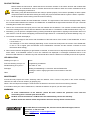
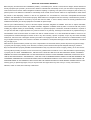
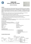
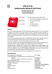
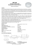
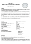
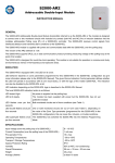
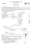
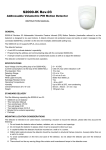
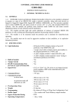
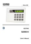
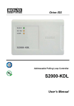
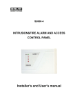
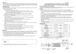
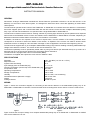
DIP-34A-04
Analogue Addressable Photoelectric Smoke Detector
INSTRUCTION MANUAL
GENERAL
DIP-34A-04 Analogue Addressable Photoelectric Smoke Detector (hereinafter referred to as the DIP-34A-04 or the
detector) is to be used in a fire alarm system. It is designed to detect fires which come with appearing of smoke within
closed spaces.
The DIP-34A-04 operates under control of the S2000-KDL or S2000-KDL-2I controller which the detector is connected to
and which supplies power and communicates data with the DIP-34A-04 via the two-wire multiplex addressable polling
loop. Up to 127 DIP-34A-04 detectors can operate under a single S2000-KDL or S2000-KDL-2I.
The DIP-34A-04 detects smoke inside its sensing chamber by sensing light reflected by smoke particles and responds
with its state to the S2000M console or Orion Pro software via the S2000-KDL or S2000-KDL-2I controller. Depending on
detected smoke amount these states can be Norm, Fire Prealarm or Fire Alarm.
In addition, the detector can respond to the console’s request with a current condition of its sensing chamber which
corresponds to its smoke or dust level. Based on this answer, an Operator of the console can make a decision about
maintenance works or waiting for a Fire Pre-alarm message in case of appearance of smoke at the beginning of a fire.
The DIP-34A-04 supports DPLS_v2.xx Multiplex Addressable Polling Loop Protocol enabling monitoring addressable loop
voltage at the detector’s location. The version of DIP-34A-04 software is 1.01.
The detector operability must be periodically tested either by using test aerosol (as described below) or by means of a
laser test tool (such as the test tool produced by the System Sensor Company).
The DIP-34A-04 is equipped with a short circuit isolator (BRIZ).
The detector is supplied with a protective cover and an “Address:” label.
SPECIFICATIONS
Sensitivity
Response Time
Ingress Protection Rating
Input Voltage (from an S2000-KDL(-2I))
Current Consumption (via the loop of the S2000-KDL(-2I))
Pre-operation Time
Operating Temperatures
Storage Temperatures
Humidity
Overall Dimensions (diameter x height)
Weight
Average Lifetime
0.05 - 0.2 dB/m (1.2 %/m to 4.7 %/m)
10 s max
IP 41
8 ÷ 11 V dc
0.5 mA max
60 s max
−30 to +55°C
−50 to +50°C
93% at +40°C, non-condensing
100×47 mm max
0.2 kg max
at least 10 years
WIRING
Figure 1 shows the connection diagram for connecting a DIP-34A-04 detector to the addressable polling loop of an
S2000-KDL or S2000-KDL-2I controller. The first terminal of the mounting base can be used to connect a cable screen.
Figure 1
Figure 2
Figure 2 shows the concept of design for a multiplex addressable polling loop of an S2000-KDL or S2000-KDL-2I if BRIZ
short circuit isolators are in use.
MOUNTING
A DIP-34A-04 is to be mounted in accordance with your applicable local standards, codes, regulations, and ordinances. If
the detector is mounted on a ceiling at a distance of no more than 4.5 m from the wall and the height of the ceiling doesn’t
exceed 3.5 m then the protected area is about 85 square meters.
There are two ways to mount the detector (see Figure 3). To install the detector to a solid surface (variant A) use the
mounting base provided (see the drilling pattern in Figure 4). In addition, you can order MK-2 mounting kit (variant B) to
attach the detector to a suspended ceiling (see the diameter of the mounting hole in the suspended ceiling in Figure 4).
DIP-34A-04 Smoke Detector
LED Status Indicator
Matchmark
Triangular Arrow and Rectangular Hole
(open here when maintaining)
5: Mounting Base
6: MK-2 Suspended Ceiling Mounting Kit (supplied separately)
1:
2:
3:
4:
Figure 3
Figure 4
To attach the detector to the mounting base, place the detector into the base and rotate clockwise until the
detector drops into place and the matchmark moulded in the detector lines up with the short mark on the
mounting base. Continue rotating clockwise until the matchmark on the detector lines up with the matchmark 3
as shown in Figure 3 (A) and the detector locks into place.
PROGRAMMING
In order the DIP-34A-04 to operate properly within the two-wire addressable polling loop of the S2000-KDL or S2000KDL-2I controller, it must be assigned to a unique number from 1 to 127 within the loop – to the address which is stored in
the DIP-34A-04 non-volatile memory. This address provides identifying the detector by the controller. Moreover, a
monitoring strategy must be defined which will be used by the controller while processing signals received from the DIP34A-04.
Programming the DIP-34A-04 Address within the S2000-KDL/S2000-KDL-2I Addressable Loop
A DIP-34A-04 is supplied with the default address of 127. This address value can be changed using either S2000(M)
console tools or PC tools such as UProg Configuration Tool.
In order to program the unique DIP-34A-04 loop address connect the detector to a S2000-KDL/S2000-KDL-2I controller
which in turns is connected to a network controller (a S2000(M) console or PC under UProg software). Then send one of
the following commands to the loop controller (for getting more information see the relevant User’s Manual):
Change the Device Address
Use the Change Device Address command specifying the old detector address and the
new detector address as the parameters (see more information in the referred
Manuals). The network controller will display the messages about disconnecting the
device with the old address and then detecting the device with newly programmed
address.
Program the Device Address
If the device address is unknown or two devices have the same address then use the
Program Device Address command specifying a required address as the parameter.
Then within 5 min press the detector light emitter or send the laser test tool beam into
it. The message about detecting the device with the newly assigned address shall be
displayed by a network controller (S2000(M)) or UProg Configuration Tool.
After programming write the set address of the detector on the “Address” label provided and stick it on the detector base.
Programming the S2000-KDL/S2000-KDL-2I to Operate the DIP-34A-04
To handle signals from a DIP-34A-04 correctly, an S2000-KDL/S2000-KDL-2I controller must be programmed with the
Zone Type parameter for this DIP-34A-04 being set to the value 1 (Smoke) or 8 (Smoke Analogue Addressable with
Variable Thresholds). To program the S2000-KDL/S2000-KDL-2I, connect it to a PC under UProg Configuration Tool and
follow the relevant programming instructions in accordance with the S2000-KDL/S2000-KDL-2I User’s Manual.
ROUTINE TESTING
Before testing the DIP-34A-04, please disconnect executive outputs of all system devices and modules that
can release an extinguishing agent or activate light and sound alarms. Notify the proper authorities that the
system is undergoing maintenance.
After testing verify that all the detectors are ready to operate properly. Then restore operability of all the system
components disconnected before testing and notify the proper authorities that the system is back in operation.
All the equipment used in testing must be known functioning.
1. Turn on the network controller and the S2000-KDL controller. The light emitter of the detector shall light steady. When
the communications between the detector and S2000-KDL is established the light emitter will flash once per 4 seconds
indicating Norm status of the detector.
2. Take a can of test aerosol and spray some of the test material into the detector. The network controller shall display
Fire Alarm message for the device with the address of the DIP-34A-04. The detector’s LED shall flash twice every 4 s.
3. Alternately, you can perform a simplified test by pressing the detector light emitter or lighting it with the laser beam of a
laser test tool. This will cause solid lighting of the detector light emitter for 3 s followed by its double flashing every 4 s.
4. The network controller will display a:
−
Fire Alarm message for the device with the address of the DIP-34A-04 if the version of the S2000-KDL in use is
1.35 or below, or
−
Test message or Fire Alarm message (depending on the current test mode) when the version of the S2000-KDL
in use is 1.36 or higher (see the Manuals for the S2000-KDL controller and the network controller for more
information about testing)
5. When the test aerosol disappears (or light emitter is released, or laser test tool is disposed) the detector must be in the
Norm status. If the S2000M console or Orion Pro software has displayed no messages mentioned above or the
detector’s LED behaves in a different way than mentioned above then the detector is unhealthy and must be replaced.
LED INDICATION
Flashing once per 4 s
Norm
Four-time flashing once per 4 s
Programming an address
Double flashing once per 4 s
Fire Alarm or Test
Solid light
Waiting for establishing a connection with the S2000-KDL
Pushing the LED or applying the laser test tool beam to the LED
Other
Trouble
MAINTENANCE
At least annually inspect the screen assembly under the detector cover. If there is any dust on the screen assembly,
clean this one with a vacuum cleaner (by pumping air).
When a Service Required message is received from the detector remove the dust from the sensing chamber.
In accordance with your rules of maintenance, maintain the detector as part of your fire alarm system.
WARNINGS
To avoid contamination of the detector, please DO NOT remove the protective cover until the
surrounding area is cleared from dirt and dust.
DO NOT remove the detector’s PCB because this automatically cancels the warranty.
DO NOT mount the detector within the premises where air velocity values exceed 15 m/s.
ZAO NVP Bolid, 4 Pionerskaya Str., Korolev 141070, Moscow Region, Russia
Phone/fax: +7 495 775-7155
Email: [email protected], [email protected]
www.bolid.ru
BOLID ONE YEAR LIMITED WARRANTY
Bolid Company and its divisions and subsidiaries («Seller»), 4 Pionerskaya Str., Korolev 141070, Moscow Region, Russia warrants its
security equipment (the «product») to be free from defects in materials and workmanship for one year from date of original purchase,
under normal use and service. Seller’s obligation is limited to repairing or replacing, at its option, free of charge for parts or labor, any
product proven to be defective in materials or workmanship under normal use and service. Seller is not responsible for results where
the product is used improperly, where it is used for any application it is not intended for, used under unacceptable environmental
conditions and mishandled or stored under improperly. Seller shall have no obligation under this warranty or otherwise if the product is
altered or improperly repaired or serviced by anyone other than the Seller. In case of defect, contact the security professional who
installed and maintains your security equipment or the Seller for product repair.
This one year Limited Warranty is in lieu of all other express warranties, obligations or liabilities. There are no express warranties,
which extend beyond the face hereof. Any implied warranties, obligations or liabilities made by seller in connection with this product,
including any implied warranty of merchantability, or fitness for a particular purpose or otherwise, are limited in duration to a period of
one year from the date of original purchase. Any action for breach of any warranty, including but not limited to any implied warranty of
merchantability, must be brought within 12 months from date of original purchase. In no case shall seller be liable to anyone for any
consequential or incidental damages for breach of this or any other warranty, express or implied, or upon any other basis of liability
whatsoever, even if the loss or damage is caused by the seller’s own negligence or fault. Some countries do not allow limitation on how
long an implied warranty lasts or the exclusion or limitation of incidental or consequential damages, so the above limitation or exclusion
may not apply to you.
Seller does not represent that the product may not be compromised or circumvented; that the product will prevent any personal injury
or property loss by burglary, robbery, fire or otherwise; or that the product will in all cases provide adequate warning or protection.
Buyer understands that a properly installed and maintained alarm may only reduce the risk of a burglary, robbery, fire or other events
occurring without providing an alarm, but it is not insurance or guarantee that such will not occur or that there will be no personal injury
or property loss as a result. CONSEQUENTLY, SELLER SHALL HAVE NO LIABILITY FOR ANY PERSONAL INJURY, PROPERTY
DAMAGE OR OTHER LOSS BASED ON A CLAIM THE PRODUCT FAILED TO GIVE WARNING. HOWEVER, IF SELLER IS HELD
LIABLE, WHETHER DIRECTLY OR INDIRECTLY, FOR ANY LOSS OR DAMAGE ARISING UNDER THIS LIMITED WARRANTY OR
OTHERWISE, REGARDLESS OF CAUSE OR ORIGIN, SELLER’S MAXIMUM LIABILITY SHALL NOT IN ANY CASE EXCEED THE
PURCHASE PRICE OF THE PRODUCT, WHICH SHALL BE THE COMPLETE AND EXCLUSIVE REMEDY AGAINST SELLER. This
warranty gives you specific legal rights, and you may also have other rights which vary from country to country. No increase or
alteration, written or verbal, to this warranty is authorized.