1
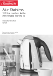
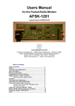
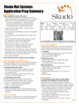
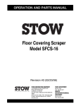
KE 1800 A ÷ KE 18500 A
* included in the maintenance kit KE 1800 A ÷ KE 18500 A.
** included in the assembled bushing.
Wiper rod**
Rod
Rod guide**
Retaining C-ring
Piston guide*
Back-up piston seal**
Assembled bushig*
One way valve Cod. 59VU02*
Plug 1/8”G Cod. 39T1/8 (KE12000 A ÷ KE18500 A)
Plug M6 Cod. 47THRM6 (KE1800 A ÷ KE7500 A)
Rod seal**
OSPAS
Non self-contained version
connecting port.
Charging hole suitable for 1/8"G cylinders connections (KE12000 A ÷ KE18500 A)
Charging hole suitable for M6 cylinders connections (KE1800 A ÷ KE7500 A)
CYLINDERS MAINTENANCE KITS
KE1800A
KE3000A
KE4700A
KE7500A
KE12000A
KE18500A
Cod.
Cod.
Cod.
Cod.
Cod.
Cod.
39BMKE01800A
39BMKE03000A
39BMKE04700A
39BMKE07500A
39BMKE12000A
39BMKE18500A
Cod. 39DMA
Cod. 39DMCILA
The DMA multi device is designed
and built to facilitate checking,
decreasing/increasing pressure or
pressurising self-contained cylinders or hosed systems.
It consists of two units:
main (DMCILA) and
secondary (DMCPVA).
Multi device for charging,
discharging and adjust
gas pressure.
Cod. 39DMCPVA
Charging set including 3 meters of
high pressure hose, 1 female Cejn
quick fit, 1 ON/OFF valve, 1 shut off
valve and 1/2-20 UNF male coupling
to connect to the nitrogen bottle.
NOTE: It is included in the 39DMA case.
Cod. 58CE03 for M6 thread
Cod. 58CE05 for 1/8G thread
Hex T-key to remove
charging hole plug and
valve retaining screw.
Cod. DDS - 1/8G
for KE12000 A ÷ KE18500 A
Cod. DDS - M6/3
for KE1800 A ÷ KE7500 A
Discharging device.
Cod. 58KNIPEX
Retaining C-Ring
removal tool.
Multipurpose pliers with
spouts.
Special Springs along with its own global
network are pleased to help you anytime for
the best result of your work.
Cod. 58CC...
Before starting any maintenance work, carefully check if the rod or the body of the cylinder are damage or wear. If yes, it is recommended to replace the cylinder immediatley
and do not procede with the maintenance
operation.
Compass key with plugs to
remove the rod top cap.
T-handle to remove
piston-rod + bushing.
Cod. 58CC03 KE3000A ÷ KE18500A
Cod. 58CC02 KE1800A
Cod. 49TB026.5 (mod. KE1800A)
Cod. 49TB035.5 (mod. KE3000A)
Cod. 49TB048.5 (mod. KE4700A)
Cod. 49TB061.5 (mod. KE7500A)
Cod. 49TB081.5 (mod. KE12000A)
Cod. 49TB106.5 (mod. KE18500A)
Reassembly guiding tube for the bushing + reassembly positioning tube for
the retaining C-ring.
KE1800A)
KE3000A)
KE4700A)
KE7500A)
KE12000A)
KE18500A)
Before starting any maintenance work carefully check the maintenance kit to correspond
to the model of cylinder for which is required.
NITROGEN GAS CYLINDERS
MAINTENANCE
KE1800A ÷ KE18500A
Marked OSPAS
Before starting any maintenance work carefully check this step-by-step manual to correspond to the model of cylinder for which is
requied.
Instructions and pictures of this step-by-step
manual could slightly differ from practise.
EYE
(mod.
(mod.
(mod.
(mod.
(mod.
(mod.
Cejin male quick fit adapter
for direct charging.
P R OT E C
N
49TN032
49TN045
49TN055
49TN070
49TN088
49TN120
Cod. 39QDFV01
for KE1800A ÷ KE7500A
Cod. 39QDFV02 for
KE12000A ÷ KE18500A
TIO
Cod.
Cod.
Cod.
Cod.
Cod.
Cod.
NOTE: It is included in the
39DMA case.
The complete assembled kit along with this
step-by-step service manual is result of
Special Springs research for the most useful
manteniance operation for Special Springs
nitrogen gas cylinders. Few minutes and the
Special Springs nitrogen gas cylinders are
regenerated as new one.
Cod. 58EAR
Cod. 58EM06 for M6 thread
Cod. 58EM08 for M8 thread
Body
Anti scratch nylon tube to set the bushing into the cylinder body to release the
retaining C-ring.
Cod. 39RFG
Cod. 39PM01
Special Springs gas
detector for easy gas
leakage.
Table manual press for
easy and safe positioning
of components.
All Special Springs step-by-step manuals
are available for download from our web
site: www.specialsprings.com
Cod. 58CD01
Torque wrench for KE
series one way valve.
9801C03002110 © All right reserved.
Special Springs S.r.l.
via Brega, 216
36027 Rosà (VI) ITALY
Tel ++39 0424 539181
Fax ++39 0424 898230
[email protected]
www.specialsprings.com
I. SKUDO REMOVAL.
II. DISCHARGING + VALVE REMOVAL for self-contained cylinders.
1. Manually remove the protective
cap SKUDO. Do not use tools. For
certain models the operation will
require a certain strain.
Preserve the protective cap
SKUDO for further reassembly.
2. Remove the protective screw
cap from the charging hole by
using the appropriate tool.
58CE05 for the 1/8 G port.
58CE03 M6/3 for the M6 port.
3. Thread DDS bleed device on
the charging port then exhaust
completely the pressure. Point
away from the operator for maximum safety.
DDS-1/8G for the 1/8 G port.
DDS-M6/3 for the M6 port.
4. Hang and release the one way
valve from the hole by using the
appropriate tool. It would be normal some oil leak from the hole
when upside down the cylinder.
58CD01 one way valve removingsetting dynamometric wrench.
XII. REASSEMBLY OF THE
UPPER RING NUT
27.Insert the positioning tube in contact with the retaining C-ring , then
by the manual press, press down
the retaining C-ring into the groove.
When the C-ring enter
correctly into the groove you will
hear a loud like “CLICK”.
49TB… conical centring guide tube.
39PM01 manual press.
28. Manually extract the assembly
piston-rod/cartridge completely.
58EM04 T-handle M4.
58EM06 T-handle M6.
58EM08 T-handle M8.
29. Cut off with all components
correctly assembled.
30. Position and thread the upper
ring nut of the cylinder by using the
appropriate compass wrench.
58CC… compass wrench.
32. Position the safety device
OSPAS into the proper hole located
in the cylinder bottom. It is severely
forbidden to press the piston-rod
into the body when the safety
device OSPAS is positioned. High
risk to damage and compromise the
functional of the safety device.
33. lock up the safety device by
using the appropriate tool.
58CE05 hex key.
XIII. POSITIONING OF OSPAS + OIL LUBICATION.
III. OSPAS REMOVAL.
Model
750
1000
1800
3000
4700
7500
12000
18500
Oil
volume
1,5 ml
2 ml
3 ml
4 ml
5 ml
8 ml
15 ml
30 ml
NOTE: Each oil dispenser contains a volume of
5 ml.
5. It is severely forbidden to press
down the piston-rod into the cylinder body before removing the
safety device OSPAS. High risk
of damaging and compromise
the regular function of the safety
device.
6. To remove the safety device
OSAPS it is necessary to remove
first the aluminium seal from the
hex hole of the screw. Use the
special drill hit, included in the
maintenance kit, and mount it on a
small hand drill.
7. The hex hole will be then completely free and ready to be used.
IV. DISCHARGING non self-contained cylinders.
8. Remove the safety device
OSAPS by using the appropriate
tool and take it away from the hole.
Preserve the safety device OSAPS
for further reassembly.
58CE05 hex key.
31. Upside-down the cylinder and
drop the lubricating oil supplied
with the kit. Please do not exceed
the volumes as indicated in the tab.
V. UPPER RING NUT REMOVAL.
XIII. CHARGING AND FORCE TEST self container cylinders.
A. For hosed cylinders exhaust
pressure through the bleed valve
on the control panel. When completely exhausted the gauge on
the panel will display 0 (zero)
pressure. Then disconnect all
cylinders from hoses and fitting.
B. Repeat then the procedure
as above indicated at points
1,2,3,4,5,6,7,8,9.
9. ONLY after the safety device
OSPAS has been removed the
piston rod can be pressed down
into the cylinder body.
10. Remove the upper ring nut on
the body by using the appropriate
wrench.
58CC… compass wrench.
34. Once re-positioned the OSPAS
device set the aluminum seal on
the hexagonal hole and smash it.
It is severely forbidden to press the
piston-rod into the body when the
safety device OSPAS is positioned.
High risk to damage and compromise the functional of the safety
device.
35. Check the correct assembly of
the pressare regulation valve on the
gas bottle, then open the main tap.
The gauge on the left will indicate
the bottle pressure.
39RP pressure regulation valve.
36. Adjust the required maximum
pressure trought the regulation
valve. The gauge on the right will
indicate the maximum allowed
pressure to charge the cylinder.
39RP pressure regulation valve.
37. Select and assemble the desired
charging adapter and thread it on the
charging port. For an easy and safety work carefully follow the instructions supplied with the charging unit.
DO NOT exceed the maximum pressure indicated for any specific model.
39DMA charging unit.
14. Remove the retaining C-ring by
using the appropriate removal tool
and pincer.
Preserve the retaining C-ring for
further reassembly.
58EAR C-ring removal tool.
58KNIPEX pincer.
38. Rached and stabilized the
desired pressure, for an easy
and safety work carefully follow
the instructions supplied with the
charging unit.
39DMA charging unit.
39. When directly charging throught
the adapter and desired pressure is
reached shut off the hose and bottle
valves and disconnect the the quick
fit coupling.
For an easy and safety work carefully follow the instructions supplied
with the charging unit.
39DMCPVA charging unit.
39QDFV… adapter for direct charging.
40. Unthread and relase the
adapter from the charging hole.
41. More precise force control can
be carried out by using the digital
force testing rigs.
FT4700 for initial forces up to 5000
daN.
IPCDIG for initial forces up to
20000 daN.
42. It is always recommended to
check leaks on the charging port
after the maintenance work and
before re-using the cylinders by
using the special gas detector.
39RFG Special Springs gas detector.
42.1. It is always recommended to
check leaks on the upper side of
the cylinders after the maintenance
work and before re-using the cylinders by using the special gas
detector.
39RFG Special Springs gas detector.
43. thread the protective screw
into the charging hole by using the
appropriate tool.
58CE05 for 1/8G charging port.
58CE03 for M6 charging port.
44. After the charging operation it
is recommended to double check
the right locking of the upper
ring nut on the body by using the
appropriate compass wrench.
58CC… compass wrench.
VI. RETAINING RING REMOVAL.
11. Position the anti scratch nylon
removal tube on the cartridge then
press down into the body for about
25 mm to set free the retaining C.
39PM01 manual press.
49TN… nylon removal tube.
12. Cylinder section with piston/rod
and cartridge completely pressed
into the body.
The retaining C-ring result free.
13. Position and clamp the cylinder
into a self - centring chuck or a
wise.
VII. PISTON ROD + CARTRIDGE REMOVAL.
VIII. CLEANING AND INSPECTION.
15. Manually extract together piston/rod/cartridge from the cylinder
body. It would be required some
strain for certain models.
58EM04 T-handle M4 thread.
58EM06 T-handle M6 thread.
58EM08 T-handle M8 thread.
17. Carefully check and clean the
cylinder body. If the body show
any wear or damage do not use it
again and replace it with a new one.
16. Slide off the cartridge from the
rod and remove seal and guide
from the piston.
Discard all of them.
IX. VALVE REASSEMBLY.
19. Carefully clean the lodging
hole of the valve with an airgun
and then position the new one way
valve supplied along with the maintenance kit. Be care on the right
position of it.
20. Position and thread the one
way valve into the hole by using
the appropriate special dynamometric tool. Torque force required
maximum 0,6 Nm. Do not exceed
the maximum torque force indicated to not damage the one way
valve.
58CD01 dynamometric wrench.
X. REASSEMBLY OF PISTON ROD + CARTRIDGE.
XIV. CHARGING AND FORCE TEST for non self-contained cylinders.
21. Assembly into the proper
groove the new guide and the new
piston seal.
Pay the best attention to not damage the seal as well as to the right
positioning.
22. Grease all over inside the
cartridge with the special grease
supplied with the kit and manually
press the pre-assembled cartridge
into the rod and slide down to
the piston shoulder. Pay the best
attention to the right orientation of
the cartridge.
A. After positioning and hosing all
the cylinders, proceed through the
quick fit device trough the control
panel for charging all the cylinders.
39DMCPVA control panel charging unit.
26. Position the retaining C-ring
into the conical centring guide
tube.
E. It is always recommended to
check leaks on the upper side of
the cylinders by using the special
gas detector.
39RFG Special Springs gas detector.
XI. REASSEMBLY OF THE RETAINING C-RING.
23. Grease all over around the
cartridge, the guide and the seal
with the special grease supplied
with the kit.
24. Position the conical centring
guide tube on the top side of the
cylinder body, then position the
piston/rod/cartridge into the tube
and assure to keep all perpendicular to the tube itself and the
cylinder body.
49TB… conical centring guide tube.
18. Carefully check and clean the
piston-rod. If the piston rod shows
any damage, wear or scratch do
not use it again and replace it with
a new one.
25. Insert the positioning tube over
the rod in contact with the upper
side of the cartridge, then by the
manual press, press down into the
cylinder body all the
assembled parts.
49TB… conical centring guide tube.
39PM01 manual press.
B. Adjust the required pressure on
the regulation valve on the bottle.
The gauge on the right will indicate
the maximum allowed pressure to
charge the cylinders.
C. Connect the female quick fit
on the male quick fit on the panel
and open the gas tap. For an easy
and safety work carefully follow
the instructions supplied with the
charging unit.
39DMCPVA control panel
charging unit.
D. It is always recommended to
check leaks on all connection to
and from the cylinder by using the
special gas detector.
39RFG Special Springs gas detector.
XV. SKUDO REASSEMBLY.
45. After the charging operation it
is recommended to double check
the right docking of the upper
ring nut on the body by using the
appropriate compass wrench.
58CC… compass wrench.
46. Manually reassembly the protective
cap SKUDO on the proper groove on
the top of the rod. It would be required
a light pressure to correctly position it.
When the protective cup SKUDO enter
correctly into the groove you will hear a
loud like “CLICK”.
9801C03002110