1
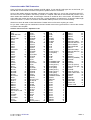
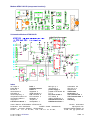
Users Manual
for the Packet-Radio-Modem
AFSK-1201
Layout Version AFSK1201-B
Issue 09/03/2004 12:03 PM
Production and Distribution: SYMEK GmbH, Datentechnik, Ulf Kumm, DK9SJ
Adress: D-70597 Stuttgart (Sonnenberg), Johannes-Krämer-Straße 34
Phone: +49 711 76 78 923, Fax: +49 711 76 78 924
eMail: info @ symek.com Internet: http://symek.com
Table of contents
Table of contents........................................................................ 1
Preface......................................................................................... 2
Technical data AFSK1201-B...................................................... 2
Short description........................................................................ 2
Bit-rate and baudrate ................................................................. 2
Copyright for Hard and Software.............................................. 2
Digital interface - 20 pin connector .......................................... 3
Signal description digital interface ................................... 3
Jumpers....................................................................................... 3
Test points and adjustment....................................................... 3
Connecting the radio to AFSK1201 .......................................... 4
Connection cables TNC/Transceiver........................................ 5
Amateur radio transceivers: Alphabetic order ................. 5
CB and other radios......................................................... 6
Cables for connection Modem - Radio: ................................... 6
Modem AFSK-1201-B (component location)) .......................... 14
Schematics Modem AFSK1201-B ............................................. 14
Index ............................................................................................ 14
Preface
This manual should help you to use the AFSK-Packet-Radio-Modem AFSK1201 in your TNC3 or TNC31
controller and to install the connection to your radio transceiver. If there are any problems, you may ask for
help via a-mail at [email protected].
Technical data AFSK1201-B
Power supply: 5 volt DC, typ 10 mA
Dimensions: ca. Length=120mm, Width=40mm, Height=25 mm, mass approx. 30 grams
Radio interface: 5-pin DIN connector, same pinning as TNC2, TNC2S, TNC2H etc. 1200 bit per second
AFSK (Audio Frequency Shift Keying) 1220/2200 Hz according to Bell 202 specifications.
AF-output level adjustable from 10 mVpp to 0.3 Vpp, Ri=:2kΩ, DC-free. Output is muted while reception. PTT :
max. 16V 0,2A to ground, input sensitivity: 200 mVpp to 10 Vpp at 25 kΩ, DC-free. (can be modified to increase sensitivity by factor 10)
Modem circuit: Texas-Instruments modem TCM3105. All frequencies are derived from a 4.433 MHz xtal.
Modem interface (digital): CMOS -level 5 volt. TXData, TXClock, RXData, RXClock, RTS CTS, DCD, + 5
volt, reset, ground. Connector: 20 pin (2x10) ribbon connector. Fits to TNC3, TNC31, TNC4 etc.
LED display: DCD (carrier detect), PTT (transmitter keying)
Jumpers and trimmers: Setting of output voltage with a 20 turn trimmer. Internal trimmers for DCD center
and trigger level. Solder jumpers for DCD source and watchdog disable.
Data Carrier Detect (DCD): Separate tone detector circuit (XR2211)
Watchdog: The PTT-switch is time-limited to approx. 40 seconds. In case of failure of the TNC, the PTT is
released after the maximum time. For tests or special applications (digipeaters with long transmission periods) the watchdog may be disabled by a solder jumper.
Measure Pins on board: DCD-PLL adjust and demodulator trigger level adjust.
Short description
A 'modem' contains modulator and demodulator circuits.
The FSK1201 converts the digital signals of a packet-radio-controller to low-frequent tones, which can be
transmitted by a FM radio. Further, it decodes the tones received by a FM radio and sends them to the
packet radio controller in digital form.
The modem AFSK1201 generates and receives audio frequency signals according the Bell 202 specifications, which is usual with amateur radio links (tone frequencies 1200 and 2200 Hz). All frequencies are
quartz controlled, adjustments are not necessary. The audio bandwidth of the signal goes from 300 Hz to
2500 Hz.
The transmit clock frequency (1200 Hz) is generated in the modem. The modem includes also the circuitry
for transmitter-keying (PTT) and transmit-time limiter (watchdog).
Bit-rate and baudrate
In this manual, the expressions bit-rate (bit/s, bit per second) and baud (Bd) are used for determining the
transmission speed. With the FSK1201 both values are equivalent, as there is exactly 1 bit transmitted with
every clock cycle. In general, it is possible to transmit more than 1 bit per clock, the speed (in bit/s) is then a
multiple of the clock rate.
Copyright for Hard and Software
All copyrights for schematics and board-layout belong to SYMEK GmbH or Ulf Kumm, Stuttgart.
The modem cannot be operated independently. So, it is a complex component and there is no need for a
EMI certification (CE-sign). When the modem is to be used in systems other than TNC3 or TNC31, the EMI
regulations have to be observed.
The contents of this manual may be copied as long as the author and the source is mentioned.
AFSK1201
Seite 2
Digital interface - 20 pin connector
Pin
Signal
Function
1
+ 5 Volt
power supply 5 volt 150 mA (from TNC)
3
+ 5 Volt
power supply 5 volt 150 mA (from TNC)
5
Reset
(not used in FSK9600)
7
DCD
AF carrier detect (from modem to TNC)
9
CTS
transmitter is keyed (from modem to TNC)
11
PTT
transmitter keying (from TNC to modem)
13
TXD
transmit data (from TNC to modem)
15
RXD*
receive data (from modem to TNC)
17
TXC
transmit clock (from modem to TNC)
19
RXC*
receive clock (from modem to TNC)
*: RXD and TXD can be encoded NRZ as well as NRZI.
Pin
Signal
2
4
6
8
10
12
14
16
18
20
Ground
Ground
Ground
Ground
Ground
Ground
Ground
Ground
Ground
Ground
Signal description digital interface
Reset (pin 5): (modem input) normally high, is pulled low for 50 ms at power-on of TNC3. (not used in
FSK1201)
DCD (pin 7) Data Carrier Detect: (modem output) High: modem receives no carrier, low: modem has detected a 1200 baud AFSK signal.
CTS (pin 9) Clear to Send: (modem output) Normally high. If the modem is ready to transmit data, the signal is low. With the FSK1200, CTS output is connected to PTT input. The TNC will wait for CTS=low before
data transmission starts.
PTT (pin 11) Push to talk, or RTS (Request to send): (modem input) normally high. When the transmitter is
to be keyed, the TNC pulls this signal to low.
TXD (pin 13) Transmit Data: (modem input): The data is latched at rising edge (low to high transition) of
transmit clock.
RXD (pin 15) Receive Data: (modem output): The data output changes at the falling edge and is valid at the
rising edge (low to high transition) of the receive clock.
TXC (pin 17) Transmit Clock: (modem output): The modem generates a clock frequency, which determines
the transmit baudrate and the data speed between TNC and modem. Transmit data signal TXD has to be
stable at the rising edge of TXC.
RXC (pin 19) Receive Clock: (modem output): the output of the receive clock recovery circuit is sent to the
TNC to synchronise the received data signal. RXD is stable at the rising edge of RXC. The frequency of
RXC corresponds to the transmit clock of the remote transmitter. If the internal clock of the modem and the
clock of the remote transmitter differ by some percent, the receive clock is adjusted by 1/16 clock cycle to
maintain synchronism.
Jumpers
Jumper J1 / J2 "DCD": AFSK-1201 has a carrier detect circuit using the XT2211 tone decoder. This circuit
is called Ädigital squelch' (however this expression isn't correct at all as the tone detection uses analog IC
only). The modem is shipped with the jumper set to XR2211-DCD, the channel is busy if a audio signal
within the normal bandwidth of a packet-radio signal is detected.
Sometimes it is desirable to define a channel to be busy if there is any audio frequency signal present (even
noise). If you prefer this, you can disconnect the XR2211 carrier detect and use the TCM3105 cattier detect
circuitry. Open the jumper J1 and close J2.
Jumper J3 "WATCHDOG": There is a time-limit for keying the transmitter. If the transwith time of approx.
40-50s is expired, the transmitter keying is released even when the controlling TNC keeps the PTT line
LOW. So, it is made sure that the transmitter never 'hangs'. This kind of protection circuit is called Watchdog.
For full duplex applications or digipeaters the watchdog may be disabled by installing a solder jumper to J3.
Test points and adjustment
Test point MP1 "DCD": The carrier detect with the ic XR2211 has to be set to the correct center frequency
by adjusting trimmer P 2. Watch the voltage at MP1 (oscilloscope) and adjust for best 1:1 duty cycle (HI:LO
ratio). The signal looks like a half way rectified sinewave, the adjustment is not critical.
AFSK1201
Seite 3
Test pin MP2 "MODEM RX": Generate a test signal with a alternating 1200 / 2200 Hz tone (frequency alternates every 1/600 second). You may use a TNC2 in TAPR mode and start the CAL command in diddlemode. Adjust the signal at MP2 to a 1:1 ratio (HI:LO) by carefullt tuning trimmer P3 (3105).
Connecting the radio to AFSK1201
Use a standard 5 pin (180°) DIN-connector. The pins are assigned as follows:
pin 1: MIC
pin 2: GND
pin 3: PTT
pin 4: SPK
pin 5:
Microphone of the radio, audio output of TNC
Ground
Push-to-talk contact, switched to ground to transmit
AF-output of the radio (loudspeaker)
not connected
Attention: the five pins are not enumerated in turn! The numbers of the contacts are printed on the black
insulating body of the plug (almost invisible figures) and on the rear panel of the TNC3/31. The pins are arranged in the following order: 3 (PTT), 5 (n.c.), 2 (GND), 4 (DEM), 1 (MOD). The middle pin 2 (GND) is made
as a soldering tag for attaching the screen wires of a microphone cable.
MIC (pin 1)
This is the AF output of the modem which is connected directly to the microphone input of the radio. You can
adjust the voltage from approx. 10 mV to 300 mV according to the sensitivity of the microphone input of the
radio.
The input impedance of the microphone input should be 10 kΩ or more. The output is decoupled (DC-free)
by a 0.1 µF ceramic capacitor. This is important when the modem is to be used with handheld radios using
the same wire for PTT and microphone.
SPK (pin 4)
This is the AF input of the modem, connected directly to the speaker output of the radio. The audio signal
should be 0,1 Vss or more (35 mV eff.). At a 8 Ω speaker this sounds 'quite weak'. More amplitude is OK,
turn the volume control to 1/4 or 'normal volume' for packet radio use with the AFSK1201.
Do not apply more than 6 volt (this is 'very loud' volume)', however you won't damage the modem as the
input is protected by two diodes. The SPK-input of AFSK1201 is coupled with a capacitor (DC-free).
PTT (pin 3)
This pin is switched to ground when the modem is set to transmit mode. All radios use a switch to ground to
key the transmitter (exception: some German police-radios). A N-channel VMOS-field effekt transistor, with a
switching capability of 25 Volt and 200 mA is used.
The 'ON' resistance of the FET is only few Ohms, the leakage current less than 1 µA.
For transceivers with other PTT circuits use an additional switching amplifier and a reed-relay with protection
diode parallel to the coil.
Many (handheld) transceivers use the same wire for PTT switch and microphone. The dc signal for the PTT
is decoupled by a capacitor. In series with the PTT-switch, there is a resistor (2 to 20 kΩ) so that the audio
signal from the microphone isn't short circuited. When pressing the PTT-key, the direct current can flow
through this resistor, keying the transmitter.
To connect such radios, you can simply connect pin 1 and pin 3 of the 5 pin DIN connector at the modem by
a approx. 4.7 kOhm miniature resistor. The common MIC and PTT wire is soldered to pin 1 of the DIN connector. Do not install the resistor inside of the TNC (at the modem board) because the resistor might cause
problems when the modem is to be used with other radios.
GND (pin 2)
Ground of the radio
Spare (pin 5)
This pin is not connected.
AFSK1201
Seite 4
Connection cables TNC/Transceiver
Here you find a list of all common amateur and CB radios. If your specific radio type can not be found, you
should refer to the manual to find the microphone, speaker and PTT connection.
Some of the cables need two separate connectors at the radio side (e.g. one for the microphone and PTT,
the other one for the speaker connection). Solder a Y-shaped cable and fix and isolate the junction of the
three cables with heatshrink tube. A total lenght of 60-80 cm would be OK in most cases. The distance between radio and modem should be not more than 1 meter (problems of interference). As long as cable length
does not exceed 1 m, there is no need to use shielded cables (however, this is recommended).
We did not check all cable circuits listed below. Please inform us if there is anything to correct.
Do you have a radio type not mentioned in the list? Please write us the type and how to connect the modem
to make the list complete.
Amateur radio transceivers: Alphabetic order
µ2E
µ4E
AOR Mini 400
AR240
AR446 ADI
C108
C401
C408
C500
C508
C520
C5200ED
C528
C558
C55D
C5608
C568
C608
C608
C7800
C8800
D410
DJ100E
DJ120
DJ460E
DJ560E
DJ580
DJ-G5T/E
DJS-1
DJS-4E
DJSF-1
DR410
DR510
DR570
DR590
DR605 T/E
EC10 Alinco 433
FT10
FT208R
FT209
FT212RH
FT23
FT290R
1
1
31
31
16
1
1
1
1
1
1
22
1
1
29
22
1
1
1
5
5
3
4
4
34
24
38
13
13
13
13
16
16
16
16
73
1
37
21
1
26
1
8
AFSK1201
FT290R II
FT40
FT470
FT4700
FT480R
FT50R
FT51
FT5100
FT51R
FT5200
FT530
FT6200
FT708R
FT709
FT712RH
FT7200
FT727
FT73
FT736
FT747GX
FT76
FT767
FT790R
FT790R II
FT8000
FT8100
FT847
FT8500
FX440
IC D1E, Z1E
IC W31E
IC02E
IC04E
IC1200
IC1210
IC1271
IC12E
IC211
IC21A
IC25
IC27
IC271
IC275 (ACC1)
26
37
1
26
7
37
1
26
1
26
1
26
21
1
26
26
1
1
27
25
1
32
8
26
39
39
39
39
36
1
1
1
1
3
3
3
1
12
14
3
3
3
33
IC275 (MIC)
IC28
IC281
IC2E
IC2WE
IC3200
IC3220
IC32E
IC45
IC45
IC47
IC471
IC475 (ACC1)
IC475 (MIC)
IC48
IC481
IC4E
IC701
IC706MK2 RJ45
IC706MK2 DIN
IC735 (ACC1)
IC735 (MIC)
IC751 (MIC)
IC820 (ACC1)
IC821 (ACC1)
IC821 (MIC)
IC970 (ACC1)
PCS9600 Azden
RV400
SRC430
TH21
TH25
TH28
TH41
TH45
TH48
TH55
TH77
TH78
TH79
TM221
TM255
TM421
3
3
40
1
37
3
3
1
3
3
3
3
33
3
3
40
1
12
72
39
33
3
3
33
33
3
33
39
24
30
2
2
2
2
2
2
2
2
2
2
6
39
6
TM441
TM451
TM455
TMV7E
TM701
TM731A
TM732A+Adapt
TM732A MIC soc
TM733 Packet
TM733A/E MIC
TM741
TM742A+Adapt
TM742A MIC soc
TR2300
TR751
TR9000
TRX4S (SYMEK)
TS140S
TS280
TS430S
TS711E (ACC2)
TS711E mic+spk
TS780
TS790E
TS811E (ACC2)
TS811 MIC+SPK
TS930S
TS940
TS950S
TW4000A
TW4100E
Yaesu 227
Yaesu 227R
6
39
39
39
6
6
35
41
39
41
41
35
41
23
19
20
74
17
15
19
17
28
19
11
17
28
19
17
19
16
16
10
9
Seite 5
CB and other radios
Note: Not all CB radios can be used for packet-radio! Make sure, packet-radio is mentioned in the manual.
Alan 27e
Alan 28d
Alan 48d, 48d80
Alan 78
Albrecht AE4100
Albrecht AE4200
Albrecht AE4400
Albrecht AE4450
Albrecht AE4500
Albrecht AE4550
Albrecht AE4600
Albrecht AE4800
Albrecht AE5000
Albrecht AE5000
Albrecht AE5100
Albrecht AE5150
Albrecht general
Albrech Alpa4000
Albrech Alpa4000
Albrecht P1000
Astracom
Conrad C-mobil
CV2000
Danita 1240
Danita Mark 5
DNT allgemein
DNT Carat
51
53
69
53
53
51
53
53
53
53
53
53
53
53
53
53
53
53
53
51
51
68
70
52
56
54
54
DNT Carat Exkus
DNT Cockpit
DNT contact III
DNT Formel 1
DNT Highway
DNT Meteor 5000
DNT Saphir
DNT Scanner
DNT Scanner FM
DNT speedy 8012
DNT Start 1
DNT Strato
DNT Strato 1
DNT Strato plus
DNT Titan
DNT Zirkon
EC10 Alinco 433
Emperor TS5010
Empire 2000
FuG (BOS-radio)
HR2510
Hotline HL1040
Jeffersn RCI2950
Kaiser 9012
Kaiser 9040 FM
Kaiser 9050 FM
Kaiser Giftzwerg
54
54
54
70
?
59
59
54
54
77
?
54
54
54
59
59
1
60
51
71
60
53
58
51
52
65
55
Kaiser KA9018/40
Kaiser KE9015/40
Kenwood
KF (BOS-radio)
Kurier 5040
Maxon 1000
Maxon 2000
Midland
Multitop (olt)
Multitop (LCD)
Pan
President George
President Grand
Pres. Jackson old
Prs. Jackson new
President James
President Lincoln
President P1000
President PC40
President PC404
stabo AE6080
stabo allgemein
stabo SH8000
stabo xf4000
stabo xf4012
stabo xf5012
stabo xf9082
55
65
64
71
53
53
53
51
61
62
52
53
52
52
65
53
60
52
52
52
66
51
67
65
65
51
76
stabo xh8082
stabo xm3000
stabo xm3082
stabo xm3400
stabo xm3500
stabo xm4000
stabo xm4012
stabo xm4042/82
stabo xm5000
stabo xm5012
stabo xm6012
stabo xm7082
stabo xm8082
stabo xrc Twinstar
Team gen.,TS404
Team Mem 5002
Wipe
Yaesu
Zodiac allgemein
Zodiac B40
Zodiac B4040
Zodiac M244
Zodiac M40
1
0
75
51
51
65
65
51
51
51
66
53
53
66
51
57
56
63
56
56
56
56
56
Cables for connection Modem - Radio:
Cable 0: these radios have no microphone-connector and are NOT suited for packet-radio
Cable 1: ICOM Handy transceiver IC2E, IC4E, IC12E, IC02E, IC04E, IC32E, µ2E, µ4E, Yaesu FT209,
FT470, FT709, FT727, FT23, FT73, FT76, Standard C201, C401, C408, C500, C520, C528, C558 etc.,
Alinco LPD EC10, stabo xh8082
pin 1 (MIC)---<br>--- 2,5 mm ear-phone plug MIC inner contact
pin 2 (GND)
---<wh>--- 2,5 mm ear-phone plug MIC outer contact
pin 2 (GND)
---<wh>--- 3,5 mm ear-phone plug SPKR outer contact
pin 4 (SPK)
---<gn>--- 3,5 mm ear-phone plug SPKR inner contact
solder 2,2 kΩ between pin 3 and pin 1 in DIN-plug
Cable 2: Kenwood Handy transceiver TH21, TH41, TH25, TH45, TH48, TH55, TH77 etc.
pin 1 (MIC)---<br>--- 3,5 mm stereo plug MIC middle contact
pin 2 (GND)
---<wh>--- 2,5 mm ear-phone plug SPKR outer contact
pin 3 (PTT)
---<yel>--- 3,5 mm stereo plug MIC outer contact
pin 4 (SPK)
---<gn>--- 2,5 mm ear-phone plug SPKR inner contact
<n.c.>-- 3,5 mm stereo plug inner contact
Cable 3: ICOM Mobile radio with 8-pin audio screw-locking line plug, as IC735, IC751, IC25, IC27, IC28,
IC821 etc.
pin 1 (MIC)---<br>--- pin 1 (MIC) (near the notch)
pin 2 (GND)
-<Schirm>- pin 7 (MIC GND) (near the notch)
pin 2 (GND)
---<wh>--- pin 6 (GND)
pin 3 (PTT)
---<yel>--- pin 5 (PTT)
pin 4 (SPK)
---<gn>--- pin 8 (SPKR) middle pin
Solder a 2,2 kΩ resistor between pin 3 and pin 1 in DIN-plug.
IC45, IC47, IC48, IC1200, IC1210, IC3200 IC3220, Alinco D410 etc.
AFSK1201
Seite 6
Cable 4: Alinco DJ100E and similar
pin 1 (MIC)---<br>--- 2,5 mm stereo plug MIC middle contact
pin 2 (GND)
---<wh>--- 2,5 mm stereo plug MIC outer contact
pin 4 (SPK)
---<gn>--- 2,5 mm stereo plug MIC inner contact
Solder a 2,2 kΩ resistor between pin 3 and pin 1 in DIN-plug.
Cable 5: Standard C7800, C8800 and similar with 7-pin audio screw-locking line plug
pin 1 (MIC)---<br>--- pin 1 (MIC)
pin 2 (GND
---<wh>--- pin 7 (GND) middle pin
pin 3 (PTT)
---<yel>--- pin 2 (PTT)
pin 4 (SPK)
---<gn>--- pin 3 (SPKR)
Cable 6: Kenwood TM221, TM421, TM701, TM731A, TM441 and similar 8-pin audio screw-locking line plug
pin 1 (MIC)---<br>--- pin 1 (MIC)
pin 2 (GND)
---<wh>--- pin 8 (GND) middle pin
pin 3 (PTT)
---<yel>--- pin 2 (PTT)
pin 4 (SPK)
---<gn>--- pin 6 (SPKR)
TM421: do not connedt to AUX-connector: There is no deemphasis. Better uns MIC and SPKR connection.
Cable 7: Yaesu FT480R and similar with 8-pin audio screw-locking line plug
pin 1 (MIC)---<br>--- pin 8 (MIC) middle pin
pin 2 (GND)
---<wh>--- pin 7 (GND) near the notch
pin 3 (PTT)
---<yel>--- pin 6 (PTT)
pin 2 (GND)
---<wh>--- 3,5 mm ear-phone plug SPKR outer contact
pin 4 (SPK)
---<gn>--- 3,5 mm ear-phone plug SPKR inner contact
Cable 8: Yaesu FT290R, FT790R with round 7-pin audio screw-locking line plug
pin 1 (MIC)---<br>--- pin 2 (MIC)
pin 2 (GND)
---<wh>--- pin 1 (GND)
pin 3 (PTT)
---<yel>--- pin 3 (PTT)
pin 4 (SPK)
---<gn>--- pin 5 (SPKR)
Cable 9: Yaesu 227R with 6-pin audio screw-locking line plug & ear-phone plug jack
pin 1 (MIC)---<br>--- pin 6 (MIC) middle pin
pin 2 (GND)
---<wh>--- pin 5 (GND)
pin 3 (PTT)
---<yel>--- pin 4 (PTT)
pin 4 (SPK)
---<gn>--- 3,5 mm ear-phone plug (SPKR) middle contact
pin 2 (GND)
---<wh>--- 3,5 mm ear-phone plug (SPKR) outer contact
Cable 10: Yaesu 227 with round 4-pin audio screw-locking line plug & ear-phone plug jack
pin 1 (MIC)---<br>--- pin 2 (MIC)
pin 2 (GND)
---<wh>--- pin 1 (GND)
pin 3 (PTT)
---<yel>--- pin 3 (PTT)
pin 4 (SPK)
---<gn>--- 3,5 mm ear-phone plug (SPKR) middle contact
pin 2 (GND)
---<wh>--- 3,5 mm ear-phone plug (SPKR) outer contact
Cable 11: Kenwood TS 790 E and similar with 13-pin plug
pin 1 (MIC)---<br>--- pin 11 (MIC)
pin 2 (GND)
---<wh>--- pin 12 and pin 4 (GND)
pin 3 (PTT)
---<yel>--- pin 9 (PTT)
pin 4 (SPK)
---<gn>--- pin 3 (SPKR)
Cable 12: ICOM IC701 or IC211 with round 4-pin audio screw-locking line plug
pin 1 (MIC)---<br>--- pin 1 (MIC)
pin 2 (GND)
---<wh>--- pin 4 (GND)
pin 3 (PTT)
---<yel>--- pin 2 (PTT)
pin 2 (GND)
---<wh>--- 6.3 mm mono earphone jack outer contact
pin 4 (SPK)
---<gn>--- 6.3 mm mono earphone jack inner contact
Cable 13: Alinco DJS-1, DJSF-1, DJS-4E, DJ-G5T etc. with ear-phone plug jack
pin 1 (MIC)---<br>--- 2,5 mm inner contact
pin 2 (GND)
---<wh>--- 2,5 mm outer contact
pin 4 (SPK)
---<gn>--- 3,5 mm inner contact
pin 2 (GND)
---<bl>--- 3,5 mm outer contact
solder 4700Ω between pin 3 and pin 1 in DIN plug.
AFSK1201
Seite 7
Cable 14: ICOM IC21A with 3-pin round plug and ear-phone plug jack
pin 1 (MIC)---<br>--- pin 1 (MIC)
pin 2 (GND)
---<wh>--- pin 3 (GND) and 3,5 mm ear-phone plug outer contact
pin 3 (PTT)
---<yel>--- pin 2 (PTT)
pin 4 (SPK)
---<gn>--- 3,5 mm ear-phone plug inner contact
Cable 15: TS280 with 8-pin DIN-plug
pin 1 (MIC)---<br>--pin 1 (MIC)
pin 2 (GND)
---<wh>--- pin 3 (GND)
pin 3 (PTT)
---<yel>--- pin 2 (PTT)
pin 4 (SPK)
---<gn>--- pin 5 (SPK)
Cable 16: TW4000A, TW4100E, DR410, DR510, DR570, DR590, ADI AR446 with 8-pin audio screw-locking
line plug and 3,5 mm ear-phone plug jack (35 cm length between MIC and SPK-plug)
pin 1 (MIC)---<br>--- pin 1 (MIC) near notch
pin 2 (GND)
---<wh>--- pin 7 (GND)
pin 2 (GND)
---<gr>--- pin 8 (GND) (middle pin)
pin 3 (PTT)
---<yel>--- pin 2 (PTT)
pin 4 (SPK)
---<gn>--- 3,5 mm ear phone jack inner contact
pin 2 (GND)
---<bl>--- 3,5 mm ear phone jack outer contact
Cable 17+18: TS140, TS940, TS811, TS711 with 13-pin DIN-plug ("ACC2")
pin 1 (MIC)---<br>--- pin 11 (MIC, DATA Input)
pin 2 (GND)
---<wh>--- pin 8, 12, 4 (GND)
pin 3 (PTT)
---<yel>--- pin 13 (PTT)
pin 4 (SPK)
---<gn>--- pin 3 (DATA)
Cable 19: TR751E, TS930S, TS430S, TS780, TS950S, with 8-pin audio screw-locking line plug
pin 1 (MIC)---<br>--- pin 1 (MIC)
pin 2 (GND)
---<wh>--- pin 7 (GND)
pin 3 (PTT)
---<yel>--- pin 2 (PTT)
pin 2 (GND)
---<bl>--- 6.3 mm mono ear phone jack outer contact
pin 4 (SPK)
---<gn>--- 6.3 mm mono ear phone jack inner contact
Cable 20: TR9000 with 6-pin audio screw-locking line plug
pin 1 (MIC)---<br>--- pin 1 (MIC)
pin 2 (GND)
---<wh>--- pin 6 (GND) (middle pin)
pin 3 (PTT)
---<yel>--- pin 2 (Stby)
pin 2 (GND)
---<bl>--- Speaker plug (ground)
pin 4 (SPK)
---<gn>--- Speaker plug (audio out)
Cable 21: Yaesu FT208R, FT708R with 6-pin mini round plug
pin 1 (MIC)---<br>--- pin 1 (MIC)
pin 2 (GND)
---<wh>--- pin 4 (GND)
pin 3 (PTT)
---<yel>--- pin 3 (PTT)
pin 4 (SPK)
---<gn>--- pin 2 (SPKR) or 3,5 mm ear phone jack (inner)
Cable 22: Standard C5200ED, C5608 with round 8-pin audio screw-locking line plug
pin 1 (MIC)---<br>--- pin 1 (MIC)
pin 2 (GND)
---<wh>--- pin 8 (GND)
pin 3 (PTT)
---<yel>--- pin 2 (PTT)
pin 4 (SPK)
---<gn>--- pin 3 (SPKR)
Cable 23: Trio TR2300 with round 4
pin 1 (MIC)---<br>--- pin 1 (MIC)
pin 2 (GND)
---<wh>--- pin 4 (GND)
pin 3 (PTT)
---<yel>--- pin 2 (PTT)
pin 2 (GND)
---<bl>--- 3,5 mm ear phone outer contact
pin 4 (SPK)
---<gn>--- 3,5 mm ear phone inner contact
Cable 24: Alinco DJ560E, Albrecht RV400 with ear-phone plug jack
pin 1 (MIC)---<br>--- 2,5 mm stereo ear-phone plug MIC middle contact
pin 2 (GND)
---<wh>--- 2,5 mm stereo ear-phone plug MIC outer contact
pin 2 (GND)
---<bl>--- 3,5 mm ear-phone plug SPKR outer contact
pin 4 (SPK)
---<gn>--- 3,5 mm ear-phone plug SPKR inner contact
solder a 470Ω resistor between pin 3 and pin 1 in DIN-plug
connect 2,5mm stereo ear-phone plug middle and inner contact
AFSK1201
Seite 8
Cable 25: Yaesu FT 747 GX (KW) with 8-pin audio screw-locking line plug
pin 1 (MIC)---<br>--- pin 8 (MIC) middle pin
pin 2 (GND)
---<wh>--- pin 7 (GND) near notch
pin 3 (PTT)
---<yel>--- pin 6 (PTT)
pin 2 (GND)
---<wh>--- 6,3 mm ear-phone plug SPKR outer contact
pin 4 (SPK)
---<gn>--- 6,3 mm ear-phone plug SPKR inner contact
Cable 26: FT4700, FT5200, FT6200, FT7200, FT212RH, FT712RH, FT290 II , FT790RII
with 8-pin audio screw-locking line plug
pin 1 (MIC)---<br>--- pin 8 (MIC)
pin 2 (GND)
---<wh>--- pin 7 (GND)
pin 3 (PTT)
---<yel>--- pin 6 (PTT)
pin 4 (SPK)
---<gn>--- pin 4 (SPKR)
the modification described in FT212 manual is not necessary (Burst/Sq).
Cable 27: FT736R with ear-phone plug jack
pin 1 (MIC)---<br>--- 3,5 mm stereo ear-phone plug inner contact
pin 2 (GND)
---<wh>--- 3,5 mm stereo ear-phone plug outer contact
pin 4 (SPK)
---<gn>--- 3,5 mm stereo ear-phone plug middle contact
pin 3 (PTT)
---<yel>--- Cynch plug inner contact
pin 2 (GND)
---<bl>--- Cynchplug outer contact
Cable 28: TS711E, TS811E with 8-pin audio screw-locking line plug
pin 1 (MIC)---<br>--- pin 1 (MIC)
pin 2 (GND)
---<wh>--- pin 7 (MIC GND)
pin 3 (PTT)
---<yel>--- pin 2 (PTT)
pin 2 (GND)
---<bl>--- 6.3 mm mono ear-phone jack outer contact
pin 4 (SPK)
---<gn>--- 6.3 mm mono ear-phone jack inner contact
Cable 29: Standard C55D with 8 pin DIN-plug
pin 1 (MIC)---<br>--- pin 7 (MIC)
pin 2 (GND)
---<wh>--- Plug-case (GND)
pin 3 (PTT)
---<yel>--- pin 6 (PTT)
pin 4 (SPK)
---<gn>--- pin 5 (SPKR)
Cable 30: Standard SR-C430 with 9 pin mini round plug
pin 1 (MIC)---<br>--- pin 2 (MIC)
pin 2 (GND)
---<wh>--- pin 1 (GND)
pin 3 (PTT)
---<yel>--- pin 3 (PTT)
pin 4 (SPK)
---<gn>--- pin 7 (SPKR)
Cable 31: AOR Mini 400, AR240 with 6 pin mini round plug
pin 1 (MIC)---<br>--- pin 6 (MIC) pin 2, 3, 4, 5, 6 count clockwise
pin 2 (GND)
---<wh>--- pin 1 (GND) (widest notch, view from solder side)
pin 3 (PTT)
---<yel>--- pin 2 (PTT)
pin 4 (SPK)
---<gn>--- pin 3 (SPKR) connect with pin 4 and pin 5, intern. MIC-disable
Cable 32: FT767 with 3 cynch plugs
pin 1 (MIC)---<br>--- Cynch plug 1 inner contact (MIC)
pin 2 (GND)
---<wh>--- Cynch plug 1 outer contact (GND)
pin 3 (PTT)
---<yel>--- Cynch plug 2 inner contact (PTT)
pin 4 (SPK)
---<gn>--- Cynch plug 3 inner contact (SPKR)
Cable 33: IC735, IC820, IC821 with 8-pin DIN plug ACC(1)
pin 1 (MIC)---<br>--- pin 4 (MOD)
pin 2 (GND)
---<wh>--- pin 2 (GND)
pin 3 (PTT)
---<yel>--- pin 3 (SEND)
pin 4 (SPK)
---<gn>--- pin 5 (9600 Baud) or pin 1 (1200 Mod)
Cable 34: Alinco DJ460E with ear-phone plug jack
pin 1 (MIC)---<br>--- 2,5 mm stereo ear-phone plug outer contact
pin 2 (GND)
---<wh>--- 2,5 mm stereo ear-phone plug inner contact
pin 2 (GND)
---<bl>--- 3,5 mm ear-phone plug outer contact
pin 4 (SPK)
---<gn>--- 3,5 mm ear-phone plug inner contact
solder a 3,3 kΩ resistor between pin 3 and pin 1 in DIN-plug
AFSK1201
Seite 9
Cable 35: Kenwood TM732A/E, TM742 A/E with MJ88 adapter 8-pin. audio screw locking line plug
and 3,5 mm ear-phone plug jack
pin 1 (MIC)---<br>--- pin 1 (MIC)
pin 2 (GND)
---<wh>--- pin 7 and pin 8
pin 3 (PTT)
---<yel>--- pin 2 (PTT)
pin 2 (GND)
---<bl>--- 3,5 mm ear-phone plug outer contact
pin 4 (SPK)
---<gn>--- 3,5 mm ear-phone plug inner contact
Cable 36: FX440 Ramsey 70cm kit transceiver
pin 1 (MIC)---<br>--- pin 1 (MIC)
pin 2 (GND)
---<wh>--- pin 2 (GND)
pin 3 (PTT)
---<yel>--- pin 3 (PTT)
pin 4 (SPK)
---<gn>--- pin 4 (SPK)
Cable 37: ICOM IC2WE, FT10/40/50R and similar with 3,5 mm stereo-ear-phone plug
pin 1 (MIC)---<br>--- 3,5 mm stereo plug MIC middle contact (near outer contact)
pin 2 (GND)
---<wh>--- 3,5 mm stereo plug MIC outer contact
pin 4 (SPK)
---<gn>--- 3,5 mm stereo plug MIC inner contact
solder a 2,2 kΩ resistor between pin 3 and pin 1 in DIN-plug
Cable 38: Alinco DJ580 connect according cable 24. Sometimes, the PTT circuit makes problems as the
transmitter keys only when PTT is pulled to ground with 470 Ohm or less. Use 220Ω in this case between
pin 1 and 3.
Cable 39: Kenwood TM255/455/451/733/V7E, Yaesu FT8100R, FT847, IC706MK2G
with 6-pin mini DIN plug for packet
pin 1 (MIC) ---<br>--pin 1 (MIC)
pin 2 (GND) ---<wh>--- pin 2 (GND)
pin 3 (PTT) ---<yel>--- pin 3 (PKS)
pin (SPK) ---<gn>--- pin 5 (PR1) 300 mV 1200 Baud
Problem: the opening at the radio is too narrow, so the connector cannot bei inserted correctly. Use readymade PS/2 keyboard cables and cut the plastic until the connector fits in place.
Cable 40: ICOM IC281 A/H/E, IC481 A/H/E with packet-connection (stereo ear-phone jack 2,5 and 3,5 mm)
pin 1 (MIC) ---<br>--2,5 mm stereo ear phone jack inner (Data Input)
pin 2 (GND) ---<wh>--- 2,5 mm stereo ear phone jack outer (GND)
pin 2 (GND) ---<wh>--- 3,5 mm stereo ear-phone jack outer (GND)
pin 3 (PTT) ---<yel>--- 2,5 mm stereo ear phone jack middle (PTT)
pin 4 (SPK) ---<gn>--- 3,5 mm stereo ear phone jack inner (AF out)
Cable 41: Kenwood TM732, 733, 742 with 8-pin Western plug (mikrophone)
pin 1 (MIC) ---<br>--pin 3 (MIC)
pin 2 (GND) ---<wh>--- pin 4 (GND MIC)
pin 2 (GND) ---<wh>--- pin 6 (GND)
pin 3 (PTT) ---<yel>--- pin 5 (PTT)
pin 4 (SPK) ---<gn>--- pin 2 (Audio 100mV)
Cable 51: Stabo, Team TS404, Astracom, Albrecht P1000 with 4-pin audio screw-locking line plug
pin 1 (MIC) ---<br>--pin 1 : Modulation
pin 2 (GND) ---<wh>--- pin 2 : GND
pin 3 (PTT) ---<yel>--- pin 4 : TX, PTT
pin 4 (SPK) ---<gn>--- pin 3 : SPKR, 'cold' end of speaker
Note: The loudspeaker is in series with pin 4 (SPKR). So you can hear a weak packet signal. If you don't like
this, insert a 3,5 mm mono ear-phone plug in the speaker socket. Solder a 100 Ω resistor between both terminals of the connector (an empty connector would interrupt the path of the audio voltage to the modem)
If you do not want to run the AF output of the radio without load, solder a 100 Ω resistor between pins 2 and
3 in the 4 pin Japan plug.
Alternatively, you can use cable 65 with additional 3,5 mm SPKR ear-phone jack.
Cable 52: President, Kaiser, Danita 1240 with 4-pin audio screw-locking line plug
pin 1 (MIC) ---<br>--pin 2 : Modulation
pin 2 (GND) ---<wh>--- pin 1 : GND
pin 3 (PTT) ---<yel>--- pin 3 : TX, PTT
pin 4 (SPK) ---<gn>--- pin 4 : SPKR
Cable 53: Albrecht AE5280, President, Alan (s.a. Cable 69), Stabo XM7082 DTMF, HL1040, XM8082 with
6-pin audio screw-locking line plug. (XM8082 has bad reception quality for packet-radio).
AFSK1201
Seite 10
pin 1 (MIC) ---<br>--pin 1 : Modulation
pin 2 (GND) ---<wh>--- pin 5 : GND
pin 3 (PTT) ---<yel>--- pin 3 : TX, PTT
pin 4 (SPK) ---<gn>--- pin 2 : SPKR
pin 5 (+12V) ---<rt>--pin 6 : + 12 V
eventually connect SPKR via 3,5 mm ear-phone jack as the speaker cannot be switched off.
At AE5280, pin 2 is the grond connection of the speaker.
Cable 54: DNT Strato, Scanner, Carat with 5 or 8-pin DIN-plug (7+center pin)
For both sides, a 5 pin DIN connector may be used. Pins 2 and 4 are cross-wired (2 to 4 and 4 to 2), pins 1
and 3 are wired 1:1 (1 to 1 and 3 to 3). So, it doesn't matter which of the two ends is plugged in the modem
or in the radio.
pin 1 (MIC) ---<br>--pin 1 : MIC
pin 2 (GND) ---<wh>--- pin 4 : GND
pin 3 (PTT) ---<yel>--- pin 3 : PTT
pin 4 (SPK) ---<gn>--- pin 2 : constant Audio
(pin 5 (+12V) ---<red>--- pin 8 (middle pin) : + 12 V)
Cable 55: Kaiser KA 9018 / 40 Giftzwerg with 5-pin DIN-plug and 3,5 mm ear-phone plug
pin 1 (MIC) ---<br>--pin 3 : Microphone
pin 2 (GND) ---<wh>--- pin 1+4 : GND
pin 3 (PTT) ---<yel>--- pin 2 : PTT
pin 2 (GND) ---<wh>--- 3,5 mm ear phone jack outer (GND)
pin 4 (SPK) ---<gn>--- 3,5 mm ear phone jack inner (SPK)
Cable 56: Danita, Wipe, Zodiac with 5-pin DIN-plug
pin 1 (MIC) ---<br>--pin 3 : Microphone
pin 2 (GND) ---<wh>--- pin 2 : GND
pin 3 (PTT) ---<yel>--- pin 1 : PTT
pin 4 (SPK) ---<gn>--- pin 5 : SPKR
Cable 57: Team Memory 5002 with 5-pin audio screw-locking line plug
pin 1 (MIC) ---<br>--pin 1 : Microphone
pin 2 (GND) ---<wh>--- pin 2 : GND
pin 3 (PTT) ---<yel>--- pin 4 : PTT
pin 4 (SPK) ---<gn>--- pin 3 : SPKR, cold end of speaker
This type is very rare.
Cable 58: Jefferson RCI 2950 with 6-pin audio screw-locking line plug and 3,5 mm ear-phone plug jack.
pin 1 (MIC) ---<br>--pin 2 : Microphone
pin 2 (GND) ---<wh>--- pin 1 : GND
pin 2 (GND) ---<wh>--- 3,5 mm ear-phone jack outer (GND)
pin 3 (PTT) ---<yel>--- pin 3 : PTT
pin 4 (SPK) ---<gn>--- 3,5 mm ear-phone jack inner (SPK)
Cable 59: DNT Zirkon, Saphir, Meteor with 6-pin Western-plug and 3,5 mm ear-phone jack.
pin 1 (MIC) ---<br>--contact 6 : Microphone
pin 2 (GND) ---<wh>--- contact 1 : GND
pin 2 (GND) ---<wh>--- 3,5 mm ear-phone jack, outer contact
pin 3 (PTT) ---<yel>--- contact 4 : PTT
pin 4 (SPK) ---<gn>--- 3,5 mm ear-phone jack, inner contact (speaker)
Cable 60: President Lincoln HR 2510, Emperor TS5010 with 5-pin audio screw-locking line plug
and 3,5 mm ear-phone
pin 1 (MIC) ---<br>--pin 1 : Microphone
pin 2 (GND) ---<wh>--- pin 2 : GND
pin 2 (GND) ---<wh>--- 3,5 mm ear-phone jack, outer contact
pin 3 (PTT) ---<yel>--- pin 3 : PTT
pin 4 (SPK) ---<gn>--- 3,5 mm ear-phone jack, inner contact (speaker)
Cable 61: Multitop (old version) with 6-pin mini-DIN-plug
pin 1 (MIC) ---<br>--pin 2 (?) : Microphone
pin 2 (GND) ---<wh>--- pin 1 (?) : GND
pin 3 (PTT) ---<yel>--- pin 4 (?) : PTT
pin 4 (SPK) ---<gn>--- pin 3 (?) : SPKR, cold end of speaker
(please compare to the radio manual)
AFSK1201
Seite 11
Cable 62: Multi-Top (LCD-display) with 6-pin mini-DIN-plug
pin 1 (MIC) ---<br>--pin 2 (?) : Microphone
pin 2 (GND) ---<wh>--- pin 1 (?) : GND
pin 2 (GND) ---<wh>--- 3,5 mm ear-phone plug, outer contact
pin 3 (PTT) ---<yel>--- pin 4 (?) : PTT
pin 4 (SPK) ---<gn>--- 3,5 mm ear-phone plug, inner contact (speaker)
(please compare to the radio manual)
Cable 63: Yaesu with 8-pin audio screw-locking line plug
pin 1 (MIC)---<br>--- pin 8 (MIC) middle pin
pin 2 (GND)
---<wh>--- pin 7 (GND) near the notch
pin 3 (PTT)
---<yel>--- pin 6 (PTT)
pin 4 (SPK)
---<gn>--- pin 4 (SPKR)
Cable 64: Kenwood with 8-pin audio screw-locking line plug
pin 1 (MIC) ---<br>--pin 1 (MIC)
pin 2 (GND) ---<wh>--- pin 8 (GND) middle pin
pin 3 (PTT) ---<yel>--- pin 2 (PTT)
pin 4 (SPK) ---<gn>--- pin 6 (SPKR)
Cable 65: Kaiser KA9040FM, 9050FM, KE9015/40 with 4-pin Mic and 3,5 mm SPKR ear-phone jack
pin 1 (MIC) ---<br>--pin 1 : Modulation
pin 2 (GND) ---<wh>--- pin 2 : GND and 3,5 mm ear-phone jack outer (GND)
pin 3 (PTT) ---<yel>--- pin 4 : TX, PTT
pin 4 (SPK) ---<gn>--- 3,5 mm ear -phone jack inner (SPK)
Cable 66: Stabo AE6080, xm6012, twinstar with 8-pin Western-plug
pin 1 (MIC) ---<br>--contact 5 : Microphone
pin 2 (GND) ---<wh>--- contact 4 : GND
pin 3 (PTT) ---<yel>--- contact 6 : PTT
pin 4 (SPK) ---<gn>--- contact 7 : Audio, NF
pin 5 (+12V) ---<rt>--contact 3 : + 12 V
Cable 67: stabo SH 8000 with 2,5 mm ear-phone (speaker) and 3,5 mm mikroph. stereo jack
pin 1 (MIC) ---<br>--3,5 mm stereo ear-phone jack middle contact : Microphone
pin 2 (GND) ---<wh>--- 3,5 mm stereo ear-phone jack outer contact : GND
pin 2 (GND) ---<wh>--- 2,5 mm ear-phone jack, outer contact : GND
pin 3 (PTT) ---<yel>--- 3,5 mm stereo ear-phone jack, inner contact : PTT
pin 4 (SPK) ---<gn>--- 2,5 mm ear-phone jack, inner contact (speaker)
Cable 68: Conrad C-mobil with 3,5 mm speaker jack and 8-pin DIN-plug (50cm distance between sockets)
pin 1 (MIC) ---<br>--pin 8: Microphone
pin 2 (GND) ---<wh>--- pin 1: GND
pin 3 (PTT) ---<yel>--- pin 7: PTT
pin 2 (GND) ---<wh>--- 3,5 mm ear-phone jack outer contact : GND
pin 4 (SPK) ---<gn>--- 3,5 mm ear-phone jack inner contact (speaker)
Cable 69: Alan 48 plus D80 with 6--pin audio screw-locking line plug and
3,5 mm ear-phone jack (see cable 53)
pin 1 (MIC) ---<br>--pin 1 : Modulation
pin 2 (GND) ---<wh>--- pin 5 : GND and 3,5 mm ear-phone jack outer contact (GND)
pin 3 (PTT) ---<yel>--- pin 3 : TX, PTT
pin 4 (SPK) ---<gn>--- 3,5 mm ear-phone jack inner contact (speaker)
Cable 70: Conrad CV2000, DNT Formel 1 etc. with 5-pin DIN-plug
pin 1 (MIC) ---<br>--pin 4 : Microphone
pin 2 (GND) ---<wh>--- pin 2 : GND
pin 3 (PTT) ---<yel>--- pin 3 : PTT
pin 4 (SPK) ---<gn>--- pin 5 : Audio, SPKR
Cable 71: BOS radios (police, fire brigade, ambulance) FuG (e.g. FuG 8b-1), KF (e.g. KF802) etc. with
10-pin NF 'NATO-headset' connector (UG77/U). PTT is switched to +12 volt. A PNP-transistor and 2x 10 kΩ
are required. These parts can be mounted inside the UG-plug.
pin 1 (MIC) ---<br>--contact F (microphone A)
pin 2 (GND) ---<wh>--- contact H (mikrophone B, ground) and contact D (ground speaker)
pin 4 (SPK) ---<gn>--- contact E (audio speaker)
pin 3 (PTT) ---<yel>--- R1 pin A
connect R2 pin A with emitter and contact B (12 V). Connect collector with contact C (PTT);
connect R1 pin B with R2 pin B and basis of transistor.
AFSK1201
Seite 12
Cable 72: ICOM IC706 MK II with 8-pin Western-plug
pin 1 (MIC) ---<br>--pin 6 Mic
pin 2 (GND) ---<wh>--- pin 5 and GND
pin 3 (PTT) ---<yel>--- pin 4 PTT
pin 4 (SPK) ---<gn>--- pin 3 AF out
Cable 73: Alinco DR605T/E with 8-pin. Western 3,5mm mono-ear-phone plug
pin 1 (MIC) ---<br>--Western pin 6
pin 2 (GND) ---<wh>--- Western pin 7 and pin 5 and 3,5 mm mono outer contact
pin 3 (PTT) ---<yel>--- Western pin 4
pin 4 (SPK) ---<gn>--- 3,5 mm mono inner contact
Cable 74: SYMEK TRX4S Data transceiver with 6-pin mini DIN Plug (NARROW mode)
pin 1 (MIC) ---<br>--pin 1 (Modulation, Data in)
pin 2 (GND) ---<wh>--- pin 2 (GND)
pin 3 (PTT) ---<yel>--- pin 3 (PTT)
pin (SPK) ---<gn>--- pin 4 (Demodulator, Data out)
Cable 75: Stabo XM3082 with 4-pin audio screw-locking line plug
pin 1 (MIC) ---<br>--pin 1 MIC
pin 2 (GND) ---<wh>--- Plug case
pin 3 (PTT) ---<yel>--- pin 4 PTT
pin 4 (SPK) ---<gn>--- pin 3 SPK (found out by trying a sample transceiver)
Cable 76: Stabo XF9082 Heimstation with 9-pin Sub-D Plug (female connector at the cable!) or 5-pin DIN
pin 1 (MIC) ---<br>--pin 7 : Microphone
pin 2 (GND) ---<wh>--- pin 5 : GND
pin 3 (PTT) ---<yel>--- pin 8 : PTT
pin 4 (SPK) ---<gn>--- pin 6 : constant audio output
pin 5 (+12V) ---<rt>--pin 4 : 10-12 V 0,1 A (Pins 1, 2, 3 and 9 not connected)
Simply use a 1:1 wired 5 pin DIN cable.
Cable 77: DNT speedy with 5-pin DIN-plug (similar to cable 70)
pin 1 (MIC) ---<br>--pin 4 : Microphone
pin 2 (GND) ---<wh>--- pin 1 : GND
pin 3 (PTT) ---<yel>--- pin 3 : PTT
pin 4 (SPK) ---<gn>--- pin 5 : Audio, SPKR
Connectors for radio and modem IMPORTANT: all connectors are shown viewing from the cable side.
The pictures show the view to the socket of the radio.
Japan 4-pin
Japan 6-pin
Japan 7-pin
Japan 8-pin
DIN 5-pin
Western 6-pin
Western 8-pin
mini-DIN 6-pin
AFSK1201
Seite 13
Modem AFSK-1201-B (component location))
Schematics Modem AFSK1201-B
Index
AF-output 4
baud (Bd) 2
bit-rate 2
carrier detect 3
CB radios 5
center frequency 3
component location 14
connection cables 5
copyright 2
CTS Clear to Send 3
DCD 3
DCD Data Carrier
Detect 3
digipeater 3
digital interface 3
DIN-connector 4
FET transistor 4
fullduplex 3
Jumpers 3
loudspeaker 4
MIC (pin 1) 4
mikrophone 4
power supply 2
printed circuit board 14
PTT 4
PTT Push to talk 3
PTT-switch 4
radio to AFSK1201 4
RXC Receive Clock 3
RXD Receive Data 3
Users Manual AFSK-Modem AFSK1201-B
Production and distribution:
SYMEK GmbH, Datentechnik,
Address: D-70597 Stuttgart (Sonnenberg),
Phone: +49 711 76 78 923, Fax: +49 711 76 78 924,
AFSK1201
schematics 14
SPK (pin 4) 4
test points 3
TRX4S data
transceiver 13
TXC Transmit Clk 3
TXD Transmit Data 3
volume 4
watchdog
Version: 09.03.2004
http://symek.com
Johannes-Krämer-Straße 34
e-mail: info @ symek.com
Seite 14