Download “was
Transcript
US007437025B2
(12) Ulllted States Patent
(10) Patent N0.:
Kychakoff et al.
(54)
(45) Date of Patent:
SENSING SYSTEM FOR DETECTION AND
5,462,358 A *
5,578,995 A * 11/1996 Bryant et a1.
TUBES IN RECOVERY AND POWER
BOILERS
5,646,338 A *
6,560,966 B1 *
( * ) Notice:
Subject to any disclaimer, the term of this
.
.
U.S.C. 154(1)) by 633 days.
)
7/1997
5/2003
340/627
Mercusot et a1. ..
.... .. 73/86
Fetescu et a1. .............. .. 60/775
* Cited by examiner
Primary ExamineriYOn Couso
(57)
ABSTRACT
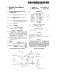
A system for detection and control of deposition on pendant
tubes .111 recqleliy and power bollérs includes one O.r more
about 4 or 8 7 microns and directl
.
.
'
.
.
roducin ima es of the
yP
.
g
g
mterlor of the bo1ler, or producmg feedmg s1gnals to a data
A 1' N '2 11/137 089
pp
0
’
(22) Filed:
10/1995 Werner ..................... .. 374/124
depos1t momtormg sensors operatmg 1n mfrared reg1ons of
Patent 15 extended or adjusted under 35
21
Oct. 14, 2008
CONTROL OF DEPOSITION ON PENDANT
(76) Inventors: George Kychakoff, 23618 SE. 25Lh s1,
Maple Valley, WA (US) 98038; Martin
A. Afromowitz, 4429 Forest Ave.,
Mercer Island, WA (US) 98040; Richard
E. Hogle, 12424 Littlerock Rd.,
Olympla’ WA (Us) 98512
(
US 7,437,025 B2
processing system for information to enable a distributed
control system by Which the boilers are operated to operate
May 24, 2005
said boilers more ef?ciently. The data processing system
mcludes an 1mage pre-processmg c1rcu1t 1n Wh1ch a 2-D
(65)
Prior Publication Data
Us Zoos/0220331 A1
(51)
(52)
00
G06K 9/00
image formed by the video data input is captured, and
includes a loW pass ?lter for performing noise ?ltering of said
video input. It also includes an image compensation system
for array compensation to correct for pixel variation and dead
Oct' 6’ 2005
2006 01
(2006'01)
cells, etc., and for correcting geometric distortion. An image
(
image pre-processing circuit for separating the image of the
'
segmentation module receives a cleaned image from the
)
U..S. Cl. ...... .... ...... ... .................... .. 382/312; 382/154
recovery boiler interior into baclqgrounds pendant tubes’ and
Fleld 0f CIaSSI?CatIOII Search
depOsitiOIL
. . . . . . . . . . . . . . . ..
382/141, 154, 173, 224, 264, 285, 312; 431/12,
431/13, 75; 110/186, 234; 162/301: 30-11;
_
_
250/3191, 330, 333
also accomplishes thresholding/clustering On
gray scale/texture and makes morphological transforms to
smooth regions, and identi?es regions by connected compo
nents. An image-understanding unit receives a segmented
See aPPhCaUOn ?le for Complete Search hlstory-
image sent from the image segmentation module and matches
References Cited
derived regions to a 3-D model ofsaid boiler. It derives a 3-D
structure the deposition on pendant tubes in the boiler and
U.S. PATENT DOCUMENTS
provides the information about deposits to the plant distrib
uted control system for more ei?cient operation of the plant
(56)
4,539,588 A *
9/1985
5,219,226
A
*
6/1993
Ariessohn et a1. ......... .. 348/164
5,355,845
A
*
10/1994
Burgess et a1.
5,368,471 A *
11/1994
Kychakoffetal. .......... .. 431/12
James
. . . . . . . . . . . . . . .
.....
. . . ..
374/124
. . . ..
122/504
pendant tube cleaning and operating systems.
12 Claims, 8 Drawing Sheets
76
80
75
70
79
)1
“was
65
US. Patent
0a. 14, 2008
Sheet 1 of8
US 7,437,025 B2
35
35
Kraft
Chemical
Recovery
Boiler
49/_
37
37
l“\
' _
q r\
Sensor
Data-Processing
System
‘\
4O
47
Distributed Control System
US. Patent
0a. 14, 2008
Sheet 2 of8
US 7,437,025 B2
60
2
Fig
92
US. Patent
0a. 14, 2008
Sheet 3 of8
US 7,437,025 B2
3
Fig
U
E
42
US. Patent
0a. 14, 2008
8%
Sheet 4 of8
US 7,437,025 B2
9;
Fig
4
55
L
3
99
[1
US. Patent
0a. 14, 2008
70
75
Sheet 6 of8
US 7,437,025 B2
f
f
65
g
8
JW
g:
Q
E,
\/
6078\
\
96
73
US. Patent
TrInRa(Pneas1mclo0tvie-hnrm)y
0a. 14, 2008
Sheet 7 of8
US 7,437,025 B2
(WMalvecrongst)h
Fig
9
US. Patent
0a. 14, 2008
Sheet 8 of8
US 7,437,025 B2
vmE w
moww
5IKI
o:3mmmg
mow?msEz:w 052 83
m:85ugms: CQ=E Qw
o9.
dm:29w6:5
6bm=>oum 26n9e8w2
coEwam
09mg 523819a
Jon?
AIR wncmEo l '
om
632m
US 7,437,025 B2
1
2
SENSING SYSTEM FOR DETECTION AND
CONTROL OF DEPOSITION ON PENDANT
TUBES IN RECOVERY AND POWER
BOILERS
Various efforts to control the rate and quantity of deposits
on the pendant tubes in the boiler have been undertaken in the
past. These include adjustments to conditions of combustion,
such as the noZZles that spray the black liquor into the com
bustion chamber, and the Way air is introduced into the com
bustion chamber. They also include systems, such as soot
The US. Government has a paid-up license in this inven
bloWers, for removing deposits on the tubes before they seri
ously impact the operation of the boiler. These control efforts
tion and the right in limited circumstances to require the
patent oWner to license others on reasonable terms as pro
vided for by the terms of Contract No. DE-FC36-99G010375
are most effective When they are immediately correlated to
by the Department of Energy.
the results they produce, but heretofore there has been no
reliable method of determining directly the amount of depos
This is related to US. Provisional Application No. 60/ 170,
Dec. 14, 2000 and further to US. Ser. No. 10/168,277 ?led on
its on the pendant tubes. Such control efforts have therefore
necessarily been based on indirect measurements and consid
Jun. 14, 2002, all entitled “Sensing System for Detection and
erations, and have usually yielded unsatisfactory results.
839 ?led on Dec. 14, 1999 and to PCT/US00/33879 ?led on
Control of Deposition on Pendant Tubes in Recovery and
PoWer Boilers”.
This invention pertains to a sensing system for detection
and control of deposition on pendant tubes in Kraft recovery
boilers, and more particularly to a mid-band infra-red imag
ing system that is tuned to a particular spectrum of infra-red
radiation to see into the otherWise visually impenetrable inte
rior of a recovery boiler in operation to provide information
about the condition of pendant steam tubes in the boiler.
BACKGROUND OF THE INVENTION
The severe environment of boilers, namely the high tem
perature, turbulent gas ?oW, particle laden atmosphere, and
intensity of radiation have made it di?icult to develop a sens
ing system for detection and control of deposition on pendant
tubes in Kraft recovery boilers that Would be economically
20
cameras for direct monitoring of pendant tube deposits have
failed to reliably produce good images over the span of large
boilers, and devices operating at longer Wavelengths have
25
In 1995, about 82% of the Wood pulp consumed at US
time, but operated in a Wavelength region of 1.5-1.8 micron,
Which has a relatively high susceptibility to light scattering by
likely to decline as neW processes come on line, it is expected
35
sodium hydroxide and sodium sul?de, called White liquor.
After cooking in the digester, the pulp is separated from the
residual liquid called black liquor. Black liquor is an aqueous
solution containing Wood lignins, organic material, and inor
ganic compounds oxidiZed in the digester during the cooking
SUMMARY OF THE INVENTION
Accordingly, this invention provides a method of directly
monitoring the depositions on recovery boiler pendant tubes.
boiler to generate steam, Which is used in the pulp mill for
The invention includes a focal plane array camera capable
45
called smelt, is collected in a molten bed at the bottom of the
boiler and discharged to a dissolving tank to be recycled into
neW White liquor.
Kraft chemical and energy recovery boilers, in Which the
black liquor is burned, are large and expensive, With capaci
50
55
The effective burning capacity of recover boilers is fre
quently determined by the processes governing the deposi
monitoring sensors feeding signals to a data processing sys
tem under control of a distributed control system. Preferably,
the deposit monitoring sensors include focal plane array cam
eras operating in the mid-infra-red band, in the region of
about 4-12 microns Wavelength. Clear images can be
obtained at a loW cost of the boiler interior and particularly of
the pendant Water and steam tubes in the boiler to enable for
the ?rst time a visual real time inspection of the condition of
the tubes and depositions thereon so that control schemes can
be implemented.
tion of fume, intermediate siZed particles, and carryover of
partially burnt liquor/ smelt drops on heat transfer surfaces of
the steam and Water tubes in the boiler, and the attendant
of creating images in a particular range of infrared radiation
that has loW absorption by molecules in the gas stream in a
chemical recovery boiler, and is not scattered signi?cantly by
particles normally present in the boiler gas stream. Another
aspect of the invention is a system of one or more deposit
ties installed in the last 30 years for pulp mills typically
exceeding 1000 tons of pulp per day. It is dif?cult economi
cally to add small incremental units of boiler capacity, so the
capacity of the chemical recovery boiler is often the factor
limiting the capacity of the entire pulp mill.
particles in the boiler gas stream.
Thus, there has long been a serious need for a deposition
detection system for recovery boiler pendant tubes to solve
the unful?lled requirement to monitor the degree and distri
bution of fume, intermediate siZed particles, and carryover
particle depositions on recovery boiler tubes.
40
process. It is concentrated and then burned in a recovery
pulp cooking and drying, and other energy requirements. The
material remaining after combustion of the black liquor,
been impractical for boiler-side use because of prohibitive
expense and the need for reliable cryogenic cooling.
US. Pat. No. 4,539,588 entitled “Imaging of Hot Infrared
Emitting Surfaces Obscured by Particulate Fume and Hot
Gasses” issued on Sep. 3, 1985 to Peter C. Ariessohn and R.
K. James discloses an improvement in the technology of the
paper and paperboard plants Was produced using the Kraft
process. Although the proportion of pulp from this source is
that Well over 50% of Wood pulp production Will still be
produced in 2020 using the Kraft process.
In the Kraft pulp production process, a ?brous material,
most commonly Wood chips, are broken doWn into pulp in a
digester under pressure in a steam-heated aqueous solution of
viable as a commercial product. Attempts to use near-IR
60
DESCRIPTION OF THE DRAWINGS
plugging of gas passages betWeen and around those pendant
The invention and its many attendant features and advan
steam and Water tubes. Much effort has been made and con
tages Will become clear upon reading the folloWing detailed
tinues to be made to improving the understanding of the
mechanism of particulate and vapor deposition on the tubes.
HoWever, there are still no reliable on-line methods for sys
tematically detecting the presence and build-up rates of these
deposits.
65
description of the preferred embodiment, in conjunction With
the folloWing draWings, Wherein:
FIG. 1 is a schematic diagram of the invention installed in
a Kraft recovery boiler;
US 7,437,025 B2
4
3
LCD display screen 80 in the case of the hand-held unit
FIG. 2 is a schematic elevation of a monitoring sensor
shoWn in FIG. 1;
shoWn in FIG. 3. The total length of the lens tube is about 36
FIG. 3 is an elevation of a hand-held sensor in accordance
inches, permitting the focal plane to be located remotely from
With this invention;
the boiler port. The lens tube 55 is cooled and purged by a
constant stream of air supplied at about 30 psi through a gas
coupling 81 into the space betWeen the inner and outer tubes
of the double-layered lens tube 55, through Which the air
?oWs and exits out through an axial opening 85 at the distal
end of the lens tube 65.
FIG. 4 is an elevation of the hand-held sensor of FIG. 3
showing the air ?oW system for the lens tube;
FIG. 5 is a sectional end elevation of the a monitoring
sensors shoWn in FIG. 2;
FIG. 6 is a sectional elevation of the a monitoring sensor
shoWn in FIG. 3 along lines 6-6 in FIG. 4;
FIG. 7 is an enlarged sectional elevation of the distal end of
Several camera models could be used: a ferroelectric array
camera, a PtSi camera, and a Si microbolometer array cam
the a monitoring sensor shoWn in FIG. 6;
FIG. 8 is a schematic diagram of the optical elements in the
sensor shoWn in FIG. 3;
FIG. 9 is a graph shoWing the light transmission over a
range of Wavelengths in a recovery boiler; and
FIG. 10 is a schematic ?oW diagram of the process of
receiving data from the monitoring sensors in FIGS. 1 and 3
to data input to the distributed control system in FIG. 1 for
control of deposition control systems in the boiler.
era. Also, an InSb array camera operating in the 3.9 micron
Wavelength region, has produced adequate images but Was
determined to be impractical because of its cost and the lim
ited lifetime of the necessary loW temperature cooling sys
tems required for operation of the camera. The ferroelectric
array camera is attractive because it does not require cryo
genic cooling, does not require frequent calibration and is
20
DESCRIPTION OF THE PREFERRED
EMBODIMENT
Turning noW to the draWings, and more particularly to FIG.
1 thereof, a deposition detection system in accordance With
such as the superimposition of artifacts such as curved lines
across the image. These problems can be addressed by chang
25
The sensor 35, shoWn in more detail in FIGS. 2 and 5-7,
cameras. The microbolometer array camera does not require
cryogenic cooling and does not use a chopper. It also has
30
The preferred camera is a ferroelectric array camera modi
35
are conducted via electrical lines 37 to a sensor data process
ing system 40, shoWn in more detail in FIG. 10 and described
in detail beloW. The hand-held sensor 36 shoWn in FIG. 3
40
vieWed on a display inside a hood 42 at the vieWer end of a
camera body 44.
A distributed control system 45, Which is the computer
system used by paper mill or poWer plant operators for con
trolling the operation of the plant, is connected to the sensor
data processing system 40 by a link 47 for advanced control of
the boiler operations in accordance With the information sup
45
3.5-4.0 microns, preferably about 3.9 microns; or infrared
radiation in a Wavelength band of about 8.5-9.0 microns,
preferably about 8.7 microns. This camera produces clear
images in the system outlined above and is inexpensive
enough to be affordable for pulp mills to purchase anduse. We
anticipate that other imaging arrays usable in our camera Will
be developed that Will be usable in the system shoWn in FIG.
The sensor shoWn in FIG. 3 includes the camera body 44
connected to the lens tube 65 by Way of an intermediate
structure 85. The intermediate structure 85 includes an adjust
able iris 90 and the lens 60, Which is axially movable to give
the lens train the ability of focus in a loW-light, Wide aperture
50
plant e?iciency.
condition. The hand-held unit 37 has a poWer sWitch 94 and
an electrical connector 96, Which provides the ability to con
nect electronically into the distributed control system 45. The
lens tube 55 is connected to a source 98 of air pressure
Turning noW to FIG. 2, one embodiment of the deposit
monitoring sensor 35 is shoWn having a focal plane array
through a pressure regulator 97 and a ?exible air hose 99.
The graph on FIG. 9 illustrates the bene?ts of operating in
camera 50 and a lens tube 55 connected to the camera 50 by
Way of a spectral band-pass ?lter 60 that limits the light
?ed to vieW infrared radiation in a Wavelength band of about
1
plied by the sensor data processing system 40, With operator
judgement and analysis Where necessary, to minimiZe depo
sition of the pendant steam tubes 49 and otherWise maximize
signi?cantly greater dynamic range than the ferroelectric
array camera. HoWever, it may require frequent (once-a-day)
re-calibration to produce acceptable images, and is signi?
cantly more expensive than the ferroelectric array camera.
converts the acquired infrared data to electrical signals, Which
converts the acquired infrared data directly to an image that is
ing required solutions to achieve satisfactory images. The
PtSi array camera requires cryogenic cooling and is quite
expensive, making it a less preferred version of the usable
this invention is shoWn installed in a Kraft recovery boiler 30.
The deposition detection system includes one or several
monitoring sensors 35, described in detail beloW, Which
acquire data in the midband infra-red spectrum Within a par
ticular ?eld of vieW from the interior of the recovery boiler.
The monitoring sensors 35 could be ?xed in position to per
manently monitor particular areas Within the boiler, or could
be integrated hand-held units 36 shoWn in FIG. 3.
relatively inexpensive. HoWever, it does use a semi-transpar
ent “chopper” Wheel to limit the intensity of the light to the
array. The chopper Wheel introduces its oWn set of problems
55
the regions of about 4 and 8.7 microns. As illustrated, there
admitted into the camera 50 to a particular band in the mid-IR
are several “Windows” available to vieWing the interior of a
spectrum.
The imaging optics consist of the double-layered steel lens
characteristics of the gas and vapors in the gas stream of a
chemical recovery boiler by virtue of the light absorption
tube 55, shoWn in FIGS. 5-7, containing a train of ZnSe or,
amorphous silicon lenses 65. The front lens 70 serves as the
objective, and has a ?eld of vieW of at least 20°. Three other
lenses 75, 76 and 77 serve as transfer optics, transporting the
60
image formed by the objective onto the focal plane array 78 of
the camera 50. The electrical signals from the imaging array
78 are processed in the electronic circuitry 79 and transmitted
to a remote processing system, in the case of the monitoring
system shoWn in FIG. 2, or displayed on a display such as an
65
chemical recovery boiler for a pulp mill. The visibility of the
boiler interior at these Wavelengths is also in?uenced by the
scattering effect of the particles in the boiler gas. The effec
tiveness of this particle scattering is greatly decreased at
longer Wavelengths, and for Wavelengths in excess of 3
microns does not signi?cantly degrade images of recovery
boiler interiors in the upper furnace and convection-pass sec
tions. By operating an a region of loW absorption and loW
scatter of the gas molecules and particles, respectively, in the
US 7,437,025 B2
6
5
an elongated lens tube containing high IR tranamissivity
optic elements and a spectral band-pass ?lter for passing
boiler gas stream, the resolution of the images that are pos
sible by infrared imaging in the chemical recovery boiler is
maximized.
Turning noW to FIG. 10, an image processing system 40
radiation in a preferred Wavelength band, coupled to a
camera sensitive to said Wavelength band, said lens tube
having a cooling channel to prevent excessive heating of
said optic elements from the boiler.
2. A deposit monitoring sensor as in claim 1, Wherein said
and a link to one version of the distributed control system is
shoWn having a video input 90 from the camera 50 to an
image pre-processing circuit 95 in Which the 2-D image is
captured and noise ?ltering is performed in a loW pass ?lter.
Array compensation is accomplished to correct for pixel
variation and dead cells, etc., and geometric distortion is
cooling channel comprises:
an inner Wall of said lens tube in Which lenses are mounted,
and an outer Wall surrounding said inner Wall;
an inlet ?uid coupling at one end of said outer tube for
corrected by image system compensation. A cleaned image
100 is sent from the image pre-processing circuit to an image
segmentation module 105 Where the image of the recovery
delivering a ?oW of cooling ?uid betWeen said inner Wall
and said outer Wall of said tube;
an outlet in said outer tube for conveying said cooling ?uid
out of said outer tube through said outlet for cooling to
boiler interior is separated into background, pendant tubes,
and deposition. Thresholding/ clustering on gray scale/texture
is accomplished and morphological transforms to smooth
prevent excessive heating from the boiler.
regions are made. Regions are identi?ed by connected com
3. A deposit monitoring sensor as in claim 1, Wherein said
ponents. The segmented image 110 is sent from the image
cooling channel comprises:
segmentation module 105 to an image-understanding unit
115 Where derived regions are matched to a 3-D model of the
recovery boiler and a 3-D structure 120 of the deposition is
an inner Wall of said lens tube has in Which lenses are
20
inferred. Those deposition estimates can be provided to the
distributed control system to update the computer model and
an air coupling for connection to a source of air pressure for
state 125 of the recovery boiler Which is fed back in a closed
loop to continually update the image understanding unit 115.
25
The deposition estimates 120 are fed to the “soot-bloWer”
control 130 for optimiZed control of the steam cleaning sys
tem for the pendant tubes 49 in the boiler.
A control scheme is envisioned that utiliZes the informa
tion from the deposition detection system to control or mini
30
35
removal Will minimiZe the steam usage as Well as tube Wear
can be optimiZed to minimize deposits on the pendant tubes.
Obviously, numerous modi?cations and variations of the
preferred embodiment described above are possible and Will
become apparent to those skilled in the art in light of this
40
45
are described for the preferred embodiment, but in some uses
of the invention, not all of these functions and advantages
Would be needed. Therefore, We contemplate the use of the
50
of the invention are disclosed herein, but not all are speci?
cally claimed, although all are covered by generic claims.
Nevertheless, it is our intention that each and every one of
55
be encompassed and protected Within the scope of the folloW
ing claims, and no dedication to the public is intended by
virtue of the lack of claims speci?c to any individual species.
Accordingly, We expressly intend that all these embodiments,
species, modi?cations and variations, and the equivalents
60
thereof, are to be considered Within the spirit and scope of the
invention as de?ned in the folloWing claims, Wherein We
claim:
The invention claimed is:
1. A deposit monitoring sensor for monitoring deposits on
8. A deposit monitoring sensor according to claim 1
Wherein:
said cooling channel in said lens tube includes an inner Wall
and an outer Wall surrounding and spaced from said
inner Wall and de?ning therebetWeen an annular space
for ?oW of cooling ?uid for conveying heat from said
outer Wall and protecting said inner Wall and said lens
tube from excessive heating from hot gasses in said
boiler.
9. A deposit monitoring sensor according to claim 8
Wherein:
said cooling channel in said lens tube includes a coupling
and advantages. Moreover, several species and embodiments
these species and embodiments, and the equivalents thereof,
silicon materials.
5. A deposit monitoring sensor according to claim 1
Wherein said preferred Wavelength band is in the region of 4
microns.
6. A deposit monitoring sensor according to claim 1
Wherein said preferred Wavelength band is in the region of 8 .7
microns.
7. A deposit monitoring sensor according to claim 1
Wherein said camera includes a focal plane array.
speci?cation. For example, many functions and advantages
inventionusing feWer than the complete set of noted functions
boiler.
4. A deposit monitoring sensor according to claim 1
Wherein:
said optic elements comprise Zinc selenide or amorphous
location of deposits and activates the steam cleaners, or “soot
bloWers”, that are most appropriate to clean the affected loca
caused by unnecessary over-cleaning. Moreover, it is noW
possible for the ?rst time to accurately relate the deposition
rate to the liquor burning parameters, so the boiler operation
delivering a ?oW of cooling air betWeen said inner Wall
and said outer Wall of said tube and for discharging said
cooling air ?oW out through said opening at said distal
end of said outer Wall;
Whereby a ?oW of cooling air is established along said lens
tube for cooling to prevent excessive heating from the
miZe further deposition, or optimiZe deposit removal pro
cesses. From the processed images, the system identi?es the
tion and prevent pluggage. Currently, the “soot-bloWers” are
operated “blind” on a timed cycle. Operating only the soot
bloWers only Where and When there are deposits needing
mounted, and an outer Wall surrounding said inner Wall,
said outer Wall having an open distal end;
65
for connecting a source of air pressure to said lens tube
for establishing a ?oW of cooling air around said inner
tube.
10. A deposit monitoring sensor according to claim 8
Wherein:
said cooling ?uid is Water.
11. A deposit monitoring sensor according to claim 9
Wherein said cooling channel in said lens tube includes an
opening at the distal end of said tube through Which said
cooling ?uid exits said lens tube.
12.A deposit monitoring sensor for monitoring deposits on
pendant tubes in a Kraft recovery boiler or a poWer boiler,
pendant tubes in a Kraft recovery boiler or a poWer boiler,
comprising:
comprising:
US 7,437,025 B2
7
at least one deposit monitoring sensor having an elongated
lens tube containing high IR transmissivity optic ele
ments and a spectral band-pass ?lter for passing radia
tion in a preferred Wavelength band, coupled to a camera
sensitive to said Wavelength bandfeeding signals for 5
producing an image for sending to a data processing
8
system for generating information about deposition on
said pendant tubes to enable a distributed control system
by Which said boilers are operated to operate said boilers
more e?iciently.
US007437025C1
(12) EX PARTE REEXAMINATION CERTIFICATE (7 594th)
United States Patent
(10) Number:
US 7,437,025 C1
Kychakoff et al.
(54)
(45) Certi?cate Issued:
SENSING SYSTEM FOR DETECTION AND
5,615,953 A
5,646,338 A
CONTROL OF DEPOSITION ON PENDANT
TUBES IN RECOVERY AND POWER
BOILERS
5,724,180 A
6,560,966 B1
Jul. 6, 2010
4/1997 Moskal
7/1997 Mercusot et al.
*
3/1998
Wellman et al.
.......... .. 359/359
5/2003 Fetescu et al.
OTHER PUBLICATIONS
(76) Inventors: George Kychakoff, 23618 SE. 25th St.,
Maple Valley, WA (U S) 98038; Martin
Weyerhaeuser Co., Maintenance and Installation Manual,
Version 2.0, High Temperature Imaging System/VIS, Pub
A. AfromoWitz, 4429 Forest Ave.,
Mercer Island, WA (US) 98040; Richard
E. Hogle, 12424 Littlerock Rd.,
lished by Sensor & Simulation Products, Tacoma, Washing
ton 98477, Nov. 30, 1988.
Olympia, WA (US) 98512
(Continued)
Primary ExamineriDeandra M Hughes
Reexamination Request:
No. 90/010,515, May 18, 2009
(57)
Reexamination Certi?cate for:
(51)
(52)
(58)
ABSTRACT
A system for detection and control of deposition on pendant
Patent No.:
Issued:
7,437,025
Oct. 14, 2008
tubes in recovery and poWer boilers includes one or more
App1.No.:
11/137,089
Filed:
May 24, 2005
about 4 or 8.7 microns and directly producing images of the
interior of the boiler, or producing feeding signals to a data
processing system for information to enable a distributed
control system by Which the boilers are operated to operate
said boilers more ef?ciently. The data processing system
includes an image pre-processing circuit in Which a 2-D
Int. Cl.
G06K 9/20
G06K 9/00
deposit monitoring sensors operating in infrared regions of
(2006.01)
(2006.01)
image formed by the video data input is captured, and
US. Cl. ...................................... .. 382/312; 382/154
Field of Classi?cation Search ...................... .. None
includes a loW pass ?lter for performing noise ?ltering of
said video input. It also includes an image compensation
system for array compensation to correct for pixel variation
See application ?le for complete search history.
(56)
and dead cells, etc., and for correcting geometric distortion.
An image segmentation module receives a cleaned image
from the image pre-processing circuit for separating the
image of the recovery boiler interior into background, pen
dant tubes, and deposition. It also accomplishes
References Cited
U.S. PATENT DOCUMENTS
3,021,386
3,609,236
4,005,327
4,539,588
4,679,891
4,709,381
5,096,502
5,219,226
5,355,845
A
A
A
A
A
A
A
A
A
2/1962
9/1971
1/1977
9/1985
7/1987
11/1987
3/1992
6/1993
10/1994
Clark
Heilman
Roosild et al.
Ariessohn et al.
Roberts
Beaudet
Carter et al.
James
Burgess et al.
thresholding/clustering on gray scale/texture and makes
morphological transforms to smooth regions, and identi?es
regions by connected components. An image-understanding
unit receives a segmented image sent from the image seg
mentation module and matches derived regions to a 3-D
model of said boiler. It derives a 3-D structure the deposition
11/1994 Kychakoffetal.
on pendant tubes in the boiler and provides the information
about deposits to the plant distributed control system for
5,462,358 A
10/1995 Werner
more e?icient operation of the plant pendant tube cleaning
5,578,995 A
11/1996 Bryant etal.
and operating systems.
5,368,471 A
30
35
Knfl
chemical
Rwmry
w
49
111
$5
37
37
US 7,437,025 C1
Page 2
OTHER PUBLICATIONS
Weyerhaeuser Co., High Temperature Imaging System/Lens
Weyerhaeuser Co., Maintenance and Installation Manual,
Tube, 1.75" Dia. Lens Tubes Maintenance Manual, Version
Version 2.0, High Temperature Imaging System/IR, Pub
1.1, Published by Sensor & Simulation Products, Tacoma,
WA 98477, copyright 1989.
lished by Sensor & Simulation Products, Tacoma, Washing
ton 98477, copyright 1989.
Weyerhaeuser Co., High temperature Imaging Sensor Lens
Tube, User Guide and Installation Manual, Published by
Sensor & Simulation Products, Tacoma, Washington 98477,
Jul. 1, 1992.
RCA ClosediCircuit Video Equipment, TC1005/01 Cam
eras, Installation and Operating Instructions, Serial No.
005838 and up, NeW Holland AVe., Lancaster, PA
1760443140 USA, Apr. 1984.
Weyerhaeuser Co., High Temperature Imaging System/ Lens
RCA ClosediCircuit Video Equipment, DXC*101/ 102,
Tube, 2.13" Dia. Lens Tubes Maintenance Manual, Version
Sony Service Manual, Apr. 1984.
1.0, Published by Sensor & Simulation Products, Tacoma,
WA 98477, copyright 1989.
Weyerhaeuser Co., High Temperature Imaging System/ Lens
SYNiFAB Inc.High Temperature & Industrial CCTV
Equipment, SE12 Solid State High Temperature Camera
Tube, 1.50" Dia. Lens Tubes Maintenance Manual, Version
System Speci?cations, Mobile, Alabama, Jul. 1995.
1.0, Published by Sensor & Simulation Products, Tacoma,
WA 98477, copyright 1989.
* cited by examiner
US 7,437,025 C1
1
EX PARTE
REEXAMINATION CERTIFICATE
ISSUED UNDER 35 U.S.C. 307
2
boiler wherein said preferred wavelength band is in the
region of 4 microns.
6. A deposit monitoring sensor [according to claim 1] for
monitoring deposits on pendant tubes in a Kraft recovery
boiler or apower boiler, comprising:
THE PATENT IS HEREBY AMENDED AS
INDICATED BELOW.
an elongated lens tube containing high IR transmissivity
optic elements and a spectral band-pass filter for pass
ing radiation in a preferred wavelength band, coupled
Matter enclosed in heavy brackets [ ] appeared in the
to a camera sensitive to said wavelength band, said
patent, but has been deleted and is no longer a part of the
patent; matter printed in italics indicates additions made
to the patent.
lens tube having a cooling channel to prevent excessive
heating of said optic elements from the boiler, wherein
said preferred wavelength band is in the region of 8.7
microns.
AS A RESULT OF REEXAMINATION, IT HAS BEEN
DETERMINED THAT:
7. A deposit monitoring sensor according to claim [1] 5
Claims 1-3 and 8-11 are cancelled.
wherein said camera includes a focal plane microbolometer
array.
Claims 4-7 and 12 are determined to be patentable as
on pendant tubes in a Kraft recovery boiler or a power boiler,
12. A deposit monitoring sensor for monitoring deposits
amended.
20
comprising:
at least one deposit monitoring sensor having an elon
4. A deposit monitoring sensor according to claim [1] 5
gated lens tube containing high IR transmissivity optic
wherein:
elements and a spectral band-pass ?lter for passing
radiation in a [preferred] wavelength band in the region
said optic elements comprise Zinc selenide or amorphous
silicon materials.
25
of 4 microns, coupled to a camera sensitive to said
5. A deposit monitoring sensor [according to claim 1] for
wavelength bandfeeding signals for producing an
monitoring deposits on pendant tubes in a Kraft recovery
image for sending to a data processing system for gen
erating information about deposition on said pendant
boiler or a power boiler, comprising: an elongated lens tube
containing high IR transmissivity optic elements and a spec
tral band-pass filter for passing radiation in a preferred
wavelength band, coupled to a camera sensitive to said
wavelength band, said lens tube having a cooling channel to
prevent excessive heating of said optic elements from the
30
tubes to enable a distributed control system by which
said boilers are operated to operate said boilers more
ef?ciently.


