1
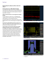
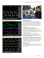
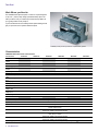
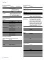
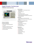
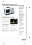
Digital Phosphor Oscilloscopes
TDS3000C Series Data Sheet
Ease-of-Use Features
Front-panel USB Host Port for Easy Storage and Transfer of
Measurement Data
25 Automatic Measurements
FFT Standard
Multiple Language User Interface
WaveAlert® Automatic Waveform Anomaly Detection
TekProbe® Interface Supports Active, Differential, and Current Probes for
Automatic Scaling and Units
Portable Design
Lightweight Design (only 7 lb./3.2 kg) for Easy Transport
Optional Internal Battery Operation Provides up to Three Hours Without
Line Power
Application Modules for Specialized Analysis
Features & Benefits
Key Performance Specifications
Advanced Analysis Module
Limit Testing Module
Telecommunications Mask Testing Module
100 MHz, 300 MHz, and 500 MHz Bandwidth Models
Extended Video Module
2 or 4 Channels
601 Serial Digital Video Module
Sample Rates up to 5 GS/s Real Time on All Channels
10 k Standard Record Length on All Channels
3,600 wfms/s Continuous Waveform Capture Rate
Suite of Advanced Triggers
Applications
Digital Design and Debug
Video Installation and Service
Power Supply Design
Education and Training
Telecommunications Mask Testing
Manufacturing Test
General Bench Testing
Data Sheet
Performance You Need at a Price You Can
Afford
Performance in an Affordable Package
The TDS3000C Series Digital Phosphor Oscilloscopes (DPO) provide you
with the performance you need at a price you can afford. Bandwidths range
from 100 MHz to 500 MHz, with up to 5 GS/s sample rates for accurate
representation of your signal.
DPOs Provide a Greater Level of Insight into Complex
Signals
To solve a problem, first you need to see it. The TDS3000C Series
combines 3,600 wfms/s continuous waveform capture rate and real-time
intensity grading so you can see the problem and solve it.
Fast waveform capture rates on a continuous basis save time by quickly
revealing the nature of faults so advanced triggers can be applied to isolate
them.
Real-time intensity grading highlights the details about the history of a
signal’s activity, making it easier to understand the characteristics of the
waveforms you’ve captured. Unlike other comparable oscilloscopes, the
history remains even after the acquisition is stopped.
Look for unintentional circuit noise with the TDS3000C Series’ FFT capability.
Quickly Debug and Characterize Signals with DRT
Sampling Technology and sin(x)/x Interpolation
The TDS3000C Series combines unique digital real-time (DRT) sampling
technology with sin(x)/x interpolation to allow you to accurately characterize
a wide range of signal types on all channels simultaneously. With the
TDS3000C Series there is no change in sampling rate when additional
channels are turned on, unlike other comparable oscilloscopes. This
sampling technology makes it possible to capture high-frequency
information, such as glitches and edge anomalies, that elude other
oscilloscopes in its class, while sin(x)/x interpolation ensures precise
reconstruction of each waveform.
Custom video triggering allows the TDS3000C Series to trigger on standards such as
RS-343 (26.2 kHz scan rate).
The TDS3000C Series provides breakthrough test speeds for telecommunications line
card testing. The telecom QUICKMENU puts all the commonly used telecom test functions
on a single menu.
2
www.tektronix.com
Digital Phosphor Oscilloscopes — TDS3000C Series
Easily transfer, document, and analyze data on your PC.
The TDS3000C Series with the TDS3LIM module is ideal for manufacturing test
applications where fast Go/No-Go decisions are required.
Easy Setup and Use
When working under tight deadlines, you need your oscilloscope to be
intuitive; you want to minimize time spent learning and relearning how to use
it. The TDS3000C Series oscilloscopes help reduce your learning curve.
Simple navigation and dedicated front-panel controls get you to where you
want to be quickly, so that you spend less time learning and more time on
the task at hand.
Trace and identify ITU-R BT.601 video signals with the TDS3SDI 601 Serial Digital Video
Module.
Simple Documentation and Analysis
The TDS3000C Series comes equipped with a USB host port so you can
easily store and transfer measurement information to your PC.
OpenChoice® PC Communication Software allows you to simply pull screen
images and waveform data into a standalone desktop application or directly
into Microsoft Word and Excel.
To complement OpenChoice, National Instruments LabVIEW
SignalExpress™ Tektronix Edition Software provides you with extended
capabilities including advanced analysis, data logging, remote instrument
control, and live waveform analysis.
If you prefer not to use a PC for analysis, the TDS3000C Series comes
standard with 25 automatic measurements, waveform add, subtract, divide,
and multiply math functions, and Fast Fourier Transform (FFT). Unlike other
comparable oscilloscopes, the TDS3000C Series math and measurement
allows you to use the full acquisition record length or isolate a specific
occurrence within an acquisition.
Instrument Control
Utilizing the built-in Ethernet port, e*Scope web-based remote control allows
you to a control TDS3000C Series oscilloscope from anywhere, using the
Internet and your PC.
WaveAlert waveform anomaly detection alerts you to any waveform that deviates from the
“normal” input such as the glitch on channel 2.
www.tektronix.com
3
Data Sheet
Work Where you Need to
The TDS3000C Series packs the power of a DPO in a compact design that
is only 5.9 in. (149 mm) deep, freeing up valuable benchtop space. And
when you need to move your oscilloscope to another lab, its portable 7 lb.
(3.2 kg) design makes for easy transport.
If your work demands even more mobility, then the optional battery pack will
give you up to three hours of operation without line power.
TDS3BATC provides you with up to three hours of portable battery operation.
Characteristics
TDS3000C Series Electrical Characteristics
Characteristic
Bandwidth
Calculated Rise Time
(typical)
Input Channels
External Trigger Input
Sample Rate on each
channel
Record Length
Vertical Resolution
Vertical Sensitivity,
1 MΩ
Vertical Sensitivity,
50 Ω
Input Coupling
Input Impedance
DC Gain Accuracy
Maximum Input
Voltage, 1 MΩ
Maximum Input
Voltage, 50 Ω
Position Range
Bandwidth Limit
Time Base Range
Time Base Accuracy
TDS3012C
TDS3014C
TDS3032C
TDS3034C
TDS3052C
TDS3054C
100 MHz
3.5 ns
100 MHz
3.5 ns
300 MHz
1.2 ns
300 MHz
1.2 ns
500 MHz
0.7 ns
500 MHz
0.7 ns
2
4
2
2
4
1.25 GS/s
1.25 GS/s
5 GS/s
5 GS/s
20 MHz, 150 MHz
1 ns to 10 s
20 MHz, 150 MHz
1 ns to 10 s
4
Included on all models
2.5 GS/s
2.5 GS/s
10 kpoints
9 bits
1 mV/div to 10 V/div
1 mV/div to 1 V/div
AC, DC, GND
1 MΩ in parallel with 13 pF or 50 Ω
±2%
150 VRMS with peaks at ≤400 V
5 VRMS with peaks at ≤30 V
20 MHz
4 ns to 10 s
20 MHz
4 ns to 10 s
±5 div
20 MHz, 150 MHz
20 MHz, 150 MHz
2 ns to 10 s
2 ns to 10 s
±20 ppm over any 1 ms time interval
Input/Output Interfaces
Ethernet Port
USB Port
GPIB Port
RS-232-C Port
VGA Video Port
External Trigger Input
4
www.tektronix.com
RJ-45 connector, supports 10Base-T LAN
Front-panel USB 2.0 host port
Supports USB flash drive
Full talk/listen modes, setting and measurements
(Optional with TDS3GV Communications Module)
DB-9 male connector, full talk/listen modes; control of all modes, settings and measurements
Baud rates up to 38,400
(Optional with TDS3GV Communications Module)
DB-15 female connector, monitor output for direct display on large VGA-equipped monitors
(Optional with TDS3GV Communications Module)
BNC connector, input impedance >1 MΩ in parallel with 17 pF; max input voltage is 150 VRMS
Digital Phosphor Oscilloscopes — TDS3000C Series
Acquisition Modes
Waveform Measurements
Description
Mode
Description
Characteristic
DPO
Captures and displays complex waveforms, random
events and subtle patterns in actual signal behavior.
DPOs provide 3 dimensions of signal information in real
time: Amplitude, time, and the distribution of amplitude
over time
High-frequency and random glitch capture. Captures
glitches as narrow as 1 ns (typical) using acquisition
hardware at all time base settings
Monitors the incoming signals on all channels and alerts
the user to any waveform that deviates from the normal
waveform being acquired
Sample data only
Waveform averaged, selectable from 2 to 512
Min-max values acquired over one or more acquisitions
Use the Single Sequence button to capture a single
triggered acquisition sequence at a time
Amplitude, Time
Cursors
Automatic Measurements Display any four measurements from any combination
of waveforms. Or display all measurements with
measurement snapshot feature. Measurements include
Period, Frequency, +Width, -Width, Rise time, Fall time,
+Duty cycle, -Duty cycle, +Overshoot, High, Low, Max,
Min, Peak-to-peak, Amplitude, Mean, Cycle mean,
RMS, Cycle RMS, Burst width, Delay, Phase, Area*1,
Cycle Area*1
Measurement Statistics Mean, Min, Max, Standard deviation. Requires
TDS3AAM application module
Thresholds
User-definable thresholds for automatic measurements;
settable in percent or voltage
Gating
Isolate a specific occurrence within an acquisition to
take measurements, using either the screen or cursors
Peak Detect
WaveAlert®
Sample
Average
Envelope
Single Sequence
Waveform Math
Trigger System
Characteristic
*1 Requires TDS3AAM application module.
Description
Main Trigger Modes
Auto (supports Roll Mode for 40 ms/div and slower),
Normal, Single Sequence
B Trigger
Trigger after time or events
Trigger After Time Range 13.2 ns to 50 s
1 to 9,999,999 events
Trigger After Events
Range
Characteristic
Description
Arithmetic
FFT
Add, subtract, multiply, and divide waveforms
Spectral magnitude. Set FFT vertical scale to Linear
RMS or dBV RMS, and FFT window to Rectangular,
Hamming, Hanning, or Blackman-Harris
Integrate, Differentiate, Define extensive algebraic
expressions including analog waveforms, math
functions, scalars, up to two user-adjustable variables
and results of parametric measurements. For example:
(Intg (Ch1-Mean(Ch1)) × 1.414 × VAR1)
Note: Requires TDS3AAM application module.
Advanced Math*1
Trigger Types
Trigger
Description
Edge
Conventional level-driven trigger. Positive or negative
slope on any channel. Coupling selections: AC, DC,
Noise Reject, HF Reject, LF Reject
Trigger on all lines or individual lines, odd/even or all
fields on NTSC, PAL, SECAM
Trigger on specific lines in broadcast and
non-broadcast (custom) standards and on analog
HDTV formats (1080i, 1080p, 720p, 480p). Requires
TDS3VID or TDS3SDI application module
Trigger on a pulse width <, >, =, ≠ to a selectable time
limit ranging from 39.6 ns to 50 s
Trigger on a pulse that crosses one threshold but fails to
cross a second threshold before crossing the first again
Trigger on pulse edge rates that are either faster or
slower than a set rate. Edges can be rising, falling, or
either
Specifies AND, OR, NAND, NOR when true or false for
a specific time
Any logic state. Triggerable on rising or falling edge of
a clock. Logic triggers can be used on combinations of
2 inputs (not 4)
Provides isolated pulse triggering required to perform
DS1/DS3 telecommunications mask testing per ANSI
T1.102 standard. Requires TDS3TMT application
module
Sequentially uses each active channel as a trigger
source
Video
Extended Video
Pulse Width
(or Glitch)
Runt
Slew Rate
Pattern
State
Comm
Alternate
*1 Requires TDS3AAM application module.
Waveform Processing
Characteristic
Description
Autoset
Single-button, automatic setup of all channels for
vertical, horizontal and trigger systems, with undo
autoset
Channel-to-channel deskew ±10 ns may be manually
entered for better timing measurements and more
accurate math waveforms
Deskew
Display Characteristics
Characteristic
Description
Display Type
Display Resolution
Interpolation
Waveform styles
Graticules
6.5 in. (165.1 mm) liquid-crystal TFT color display
640 horizontal × 480 vertical pixels (VGA)
Sin(x)/x
Dots, vectors, variable persistence, infinite persistence
Full, grid, crosshair, and frame. NTSC, PAL, SECAM,
and vectorscope (100% and 75% color bars) with
optional TDS3VID or TDS3SDI application modules
YT, XY, and Gated XYZ (XY with Z-axis blanking
available on 4-channel instruments only)
Format
Power Source
Characteristic
Description
AC line power
Source voltage
Source frequency
100 VRMS to 240 VRMS ±10%
45 Hz to 440 Hz from 100 V to 120 V
45 Hz to 66 Hz from 120 V to 240 V
Power consumption
75 W maximum
Battery power
Requires TDS3BATC, rechargeable lithium ion battery
pack
Operating time, typical 3 hours
www.tektronix.com
5
Data Sheet
Environmental and Safety
Characteristic
Temperature
Humidity
Altitude
Electromagnetic
Compatibility
Safety
Standard Accessories
Operating
Non-operating
0 ºC to +50 ºC
-40 ºC to +71 ºC
Operating and Nonoperating:
Up to 95% RH at or below +30 ºC
Operating and Nonoperating:
Up to 45% RH +30 ºC up to +50 ºC
To 3,000 m
15,000 m
Meets or exceeds EN61326 Class A, Annex D
radiated and conducted emissions and immunity;
EN6100-3-2 AC Powerline Harmonic Emissions;
EN6100-3-3 Voltage Changes, Fluctuation, and
Flicker; FCC 47 CFR, Part 15, Subpart B, Class
A; Australian EMC framework
UL61010B-1, CSA1010.1, IEC61010-1, EN61010-1
Accessory
One P6139B, 500 MHz,
10x passive probe per
channel
User Manual and
Translated Front-panel
Overlay
Power Cord
Accessory Tray
Protective Front Cover
OpenChoice® PC
Communication Software
NI LabVIEW
SignalExpress™
Tektronix Edition LE
Physical Characteristics
Instrument
Dimensions
mm
in.
Width
Height
Depth
375.0
176.0
149.0
14.8
6.9
5.9
Weight
kg
lb.
Instrument only
with accessories
3.2
4.5
7.0
9.8
Package Dimensions
mm
in.
Width
Height
Depth
502.0
375.0
369.0
19.8
14.8
14.5
Instrument Shipping
Traceable Certificate of
Calibration
Documentation CD
3 Year Warranty
Description
Please specify preferred language option - see chart
below
Please specify plug option - see chart below
Enables fast and easy communication between
Windows PC and the TDS3000C Series through
LAN, GPIB, or RS-232. Transfer and save settings,
waveforms, measurements, and screen images
A fully interactive measurement software environment
optimized for the TDS3000C Series. Enables you
to acquire, generate, analyze, compare, import,
and save measurement data and signals using an
intuitive drag-and-drop user interface that does not
require any programming. Standard TDS3000C
Series support for acquiring, controlling, viewing, and
exporting your live signal data is permanently available
through the software. A 30-day trial period of the full
version provides additional signal processing, advance
analysis, mixed signal, sweeping, limit testing, and
user-defined step capabilities. Order SIGEXPTE for
permanent full version capability
NIM/NIST
Covering all labor and parts excluding probes and
accessories
Rackmount (RM3000)
Dimension
mm
in.
Options
Width
Height
Depth
484.0
178.0
152.0
19.0
7.0
6.0
Option
Description
Opt. A0
Opt. A1
Opt. A2
Opt. A3
Opt. A5
Opt. A6
Opt. A10
Opt. A11
Opt. A99
North America
Universal Euro
United Kingdom
Australia
Switzerland
Japan
China
India
No power cord
Ordering Information
TDS3000C Series Digital Phosphor Oscilloscopes
Model
Description
TDS3012C
TDS3014C
TDS3032C
TDS3034C
TDS3052C
TDS3054C
100 MHz, 2 Channel, 1.25 GS/s
100 MHz, 4 Channel, 1.25 GS/s
300 MHz, 2 Channel, 2.5 GS/s
300 MHz, 4 Channel, 2.5 GS/s
500 MHz, 2 Channel, 5 GS/s
500 MHz, 4 Channel, 5 GS/s
6
www.tektronix.com
Language Options
Option
Description
Opt. L0
Opt. L1
Opt. L2
Opt. L3
Opt. L4
Opt. L5
Opt. L6
Opt. L7
Opt. L8
Opt. L9
Opt. L10
Opt. L99
English
French
Italian
German
Spanish
Japanese
Portuguese
Simplified Chinese
Traditional Chinese
Korean
Russian
No manual
Digital Phosphor Oscilloscopes — TDS3000C Series
Recommended Accessories
Recommended Probes
Accessory
Description
Probe
Description
TDS3GV
TDS3AAM
GPIB, VGA, RS-232 interface
Advanced Analysis Module. Adds extended math
capability, arbitrary math expressions, measurement
statistics, and additional automated measurements
Limit Testing Module. Adds custom waveform limit
testing capabilities
Telecom Mask Testing Module. Adds pass/fail
compliance of ITU-T G.703 and ANSI T1.102
standards, custom mask testing, and more
Extended Video Analysis Module. Adds video
quickmenu, autoset, hold, line count trigger, video
picture mode, vectorscope*2 mode, HDTV format
trigger graticules, and more
Serial/Digital Video Module. Adds 601 serial digital
video to analog video conversion, video picture,
vectorscope*2, and analog HDTV triggering capabilities,
and more
Lithium-ion battery pack for up to 3 hours continuous
operation without line power
Soft case for carrying instrument
Hard plastic case for carrying instrument
(requires AC3000)
Rackmount kit
NI LabVIEW SignalExpress™ Tektronix Edition
Software full version
English only (071-2507-xx)
Extensive instructions and step-by-step lab exercises
provide education about the operation of TDS3000C
Series Oscilloscopes. Kit includes self-paced CD-ROM
based manual and signal source board. Optional
hardcopy manual available for order separately
P6243
P5205
P5210
P5100
TCP202
TCP303*3
TCP305*3
TCP312*3
TCPA300
TCP404XL*4
TCPA400
ADA400A
1 GHz, ≤1 pF input C 10x active probe
1.3 kV, 100 MHz high-voltage differential probe
5.6 kV, 50 MHz high-voltage differential probe
2.5 kV, 100x high-voltage passive probe
50 MHz, 15 A AC/DC current probe
15 MHz, 150 A current probe
50 MHz, 50 A current probe
100 MHz, 30 A current probe
100 MHz probe amplifier
2 MHz, 500 A current probe
50 MHz probe amplifier
100x, 10x, 1x, 0.1x high-gain differential amplifier
TDS3LIM
TDS3TMT
TDS3VID
TDS3SDI
TDS3BATC
AC3000
HCTEK4321
RM3000
SIGEXPTE
Service Manual
TNGTDS01
*2 Vectorscope does not support composite video.
*3 Requires TCPA300 probe amplifier.
*4 Requires TCPA400 probe amplifier.
Service Options
Description
Option
Available at time of purchase
Opt. CA1
Provides a single calibration event or coverage for the
designated calibration interval, whichever comes first
Calibration Data Report
Repair Service - 5 year
Opt. D1
Opt. R5
Available after purchase
TDS30xxC-CA1
TDS30xxC-R1PW
TDS30xxC-R2PW
TDS30xxC-R5DW
Provides a single calibration event or coverage for the
designated calibration interval, whichever comes first
Repair service coverage 1 year post warranty
Repair service coverage 2 years post warranty
Repair service coverage 5 years (includes product
warranty period); 5-year period starts at time of
customer instrument purchase
Tektronix is registered to ISO 9001 and ISO 14001 by SRI Quality System Registrar.
Product(s) complies with IEEE Standard 488.1-1987, RS-232-C, and with Tektronix
Standard Codes and Formats.
www.tektronix.com
7
Data Sheet
Contact Tektronix:
ASEAN / Australasia (65) 6356 3900
Austria 00800 2255 4835*
Balkans, Israel, South Africa and other ISE Countries +41 52 675 3777
Belgium 00800 2255 4835*
Brazil +55 (11) 3759 7627
Canada 1 800 833 9200
Central East Europe and the Baltics +41 52 675 3777
Central Europe & Greece +41 52 675 3777
Denmark +45 80 88 1401
Finland +41 52 675 3777
France 00800 2255 4835*
Germany 00800 2255 4835*
Hong Kong 400 820 5835
India 000 800 650 1835
Italy 00800 2255 4835*
Japan 81 (3) 6714 3010
Luxembourg +41 52 675 3777
Mexico, Central/South America & Caribbean 52 (55) 56 04 50 90
Middle East, Asia, and North Africa +41 52 675 3777
The Netherlands 00800 2255 4835*
Norway 800 16098
People’s Republic of China 400 820 5835
Poland +41 52 675 3777
Portugal 80 08 12370
Republic of Korea 001 800 8255 2835
Russia & CIS +7 (495) 7484900
South Africa +41 52 675 3777
Spain 00800 2255 4835*
Sweden 00800 2255 4835*
Switzerland 00800 2255 4835*
Taiwan 886 (2) 2722 9622
United Kingdom & Ireland 00800 2255 4835*
USA 1 800 833 9200
* European toll-free number. If not accessible, call: +41 52 675 3777
Updated 10 February 2011
For Further Information. Tektronix maintains a comprehensive, constantly expanding
collection of application notes, technical briefs and other resources to help engineers working
on the cutting edge of technology. Please visit www.tektronix.com
Copyright © Tektronix, Inc. All rights reserved. Tektronix products are covered by U.S. and foreign patents,
issued and pending. Information in this publication supersedes that in all previously published material.
Specification and price change privileges reserved. TEKTRONIX and TEK are registered trademarks of
Tektronix, Inc. All other trade names referenced are the service marks, trademarks, or registered trademarks
of their respective companies.
16 Mar 2012
www.tektronix.com
41W-12482-20