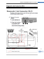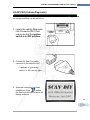
1
2007/7/17 2 MICROCORE SCAN‐‐DIY CAN OBD/EOBD‐II SC CAN TOOL USER’S MANUAL SSCAN‐DIY Codereader‐Pro | felix.Xu SCAN‐DIY CAN OBD/EOBD‐II SCAN Tool User’s Manual ‐ 2 ‐ Table of Contents -- Introduction --------------------------------------------------------------------------------------Product explanation ------------------------------------------------------------------------------------------------------ 3 Safety Precautions--------------------------------------------------------------------------------------------------------- 5 Vehicle Service Information------------------------------------------------------------------------------------------15 Introduction to On-Board Diagnostics OBD II------------------------------------------------------------17 -Diagnostic Link Connector (DLC) ------------------------------------------------------------------------18 -Data Link Connector (DLC) Pins--------------------------------------------------------------------------19 -OBD II Diagnostic Trouble Codes (DTCs) ---------------------------------------------------------20 --Using The Scan Tool-----------------------------------------------------------------------------The Scan Tool ---------------------------------------------------------------------------------------------------------------22 Keypad Functions ---------------------------------------------------------------------------------------------------------23 Display Functions ---------------------------------------------------------------------------------------------------------24 Getting Started --------------------------------------------------------------------------------------------------------------25 Settings: Adjustments --------------------------------------------------------------------------------------------------26 About …--------------------------------------------------------------------------------------------------------------------------28 Malfunction Indicator Lamp (MIL)-------------------------------------------------------------------------------29 --Vehicle Diagnostic--------------------------------------------------------------------------------SCAN CAR (Vehicle Diagnostic) --------------------------------------------------------------------------------30 1) READ DTCs-----------------------------------------------------------------------------------------------------33 2) ERASE DTCs---------------------------------------------------------------------------------------------------34 3) VIEW LIVE DATA---------------------------------------------------------------------------------------------35 -OBD-II GENERIC OPERATIONAL DATA ITEMS------------------------------------36 -OBD-II GENERIC OPERATIONAL DATA ITEMS (CONT..) ------------------37 4) VIEW FREEZE FRAME----------------------------------------------------------------------------------38 5) MIL STATUS ----------------------------------------------------------------------------------------------------39 6) I/M Readiness---------------------------------------------------------------------------------------------------40 7) VIEW VEHICLE INFORMATION-------------------------------------------------------------------42 LAST SCAN -------------------------------------------------------------------------------------------------------------------43 Select M.F (SELECT MANUFACTORY) -------------------------------------------------------------------45 -SUPPORT MANUFACTORY--------------------------------------------------------------------------------46 --Appendix--------------------------------------------------------------------------------------------Appendix A – PID Definitions---------------------------------------------------------------------------------------47 Appendix B – Glossary-------------------------------------------------------------------------------------------------50 Appendix C – Support Manufactory Vehicle-------------------------------------------------------------61 Appendix D – Common OBDII DTC Definitions reference-------------------------------------68 Copyright Information----------------------------------------------------------------------------------------------------88 Microcore | SCAN‐DIY Codereader‐Pro ‐ 2 ‐ SCAN‐DIY CAN OBD/EOBD‐II SCAN Tool User’s Manual rve d. ‐ 3 ‐ The Product is: rig hts r ese Codereader Codereader‐Pro Scanner OEM product Product Features: Scanner Yes OEM product □ Yes Yes □ .,L td All Codereader‐Pro Yes Yes □ Yes Yes Yes Yes Yes Yes □ □ □ Yes Yes Yes Yes □ □ No Yes No Yes Yes No Yes Yes Yes □ □ □ Codereader Codereader‐Pro Yes Yes Yes □ Yes Yes Yes □ Yes Yes Yes □ Yes Yes Yes □ Yes Yes Yes □ No No Yes □ GM OBDI Cable No No Yes □ rig Codereader Displays the DTC definitions on Yes screen unlike previous models works with CAN‐equipped Yes vehicles Reads and clears all generic, and Yes some manufacturer, specific DTCs Resets check engine lights Yes Views OBD‐II Freeze Frame data Yes Determines the Malfunction No Indicator lamp (MIL) status I/M readiness status No Retrieves the Vehicle Identification No Ford OBDI Cable No No Yes □ Chrysler OBDI Cable No No Yes □ PC Upgrade Software CD No No Yes □ Ele ctr on ic Co Yes Number (VIN) Scanning live data Saves scanning Data co re PC Software upgrade The Product Kit Includes: Mi cro Base Tool 00 7 OBDII Cable Manual/CD Manu Index Co ‐ 3 ‐ py ht Updated Cable ©2 Box Microcore | SCAN‐DIY Codereader‐Pro Scanner OEM product ese Features: Display: 128x64 pixel LCD with contrast adjustment and backlight Easy‐to‐Read screen and also saves up to 38 scans for later viewing. Operating temperature:20℃‐50 ℃(‐4℉ to 122 ℉) Operation Voltage : DC 9 ~15V provided by vehicle battery td .,L Co on ic rig ht ©2 00 7 Mi cro co re Ele ctr Support Protocol: 1) SAEJ1850 PWM 2) SAEJ1850 VPW 3) ISO14230 4) ISO9141 5) ISO157654 (CAN BUS) All rig hts r ‐ 4 ‐ rve d. SCAN‐DIY CAN OBD/EOBD‐II SCAN Tool User’s Manual Co py ‐ 4 ‐ Microcore | SCAN‐DIY Codereader‐Pro SCAN‐DIY CAN OBD/EOBD‐II SCAN Tool User’s Manual rve d. ‐ 5 ‐ Safety Precautions All rig hts r ese For your safety, read this manual thoroughly before operating your Scan Tool. Always refer to and follow safety messages and test procedures provided by the manufacturer of the vehicle or equipment being tested. The safety messages presented below and throughout this user’s manual are reminders to the operator to exercise extreme care when using this test instrument. td Read All Instructions Co .,L Read, understand and follow all safety messages and instructions in this manual and on the test equipment. Safety messages in this section of the manual contain a signal word with a three-part message and, in some instances, an icon. Ele ctr on ic Safety Messages Safety messages are provided to help prevent personal injury and equipment damage. All safety messages are introduced by a signal word. The signal word indicates the level of the hazard in a situation. The types of safety messages are. co re Mi cro Indicates a possible hazardous situation which, if not avoided, will result in death or serious injury to operator or bystanders. 00 7 Indicates a possible hazardous situation which, if not avoided, could result in death or serious injury to operator or bystanders. ©2 Indicates a possible hazardous situation which, if not avoided, may result in moderate or minor injury to operator or bystanders. py Indicates a condition which, if not avoided, may result in damage to test equipment or vehicle. Co ‐ 5 ‐ rig ht Microcore | SCAN‐DIY Codereader‐Pro ‐ 6 ‐ rve d. SCAN‐DIY CAN OBD/EOBD‐II SCAN Tool User’s Manual Safety Precautions ese 3 Safety Type: rig hts r Safety messages contain three different type: • Normal type states the hazard. All • Bold type states how to avoid the hazard. • Italic type states the possible consequences of not avoiding the hazard. td Icons used: Co .,L An icon, when present, gives a graphical description of a potential hazard. on ic Example: co re Ele ctr Engine systems can malfunction expelling fuel, oil vapors, hot steam, hot toxic exhaust gases, acid, refrigerant and other debris. ©2 00 7 Mi cro Safety goggles and protective gloves must be Worn by the operator and any bystanders. Even if everyday eyeglasses have impact resistant lenses, they are NOT safety glasses. rig ht Engine systems that malfunction can cause injury. Co py ‐ 6 ‐ Microcore | SCAN‐DIY Codereader‐Pro SCAN‐DIY CAN OBD/EOBD‐II SCAN Tool User’s Manual rve d. ‐ 7 ‐ rig hts r ese Safety Precautions Ele ctr on ic Co .,L td All Risk of electric shock. • Do not exceed voltage limits between inputs indicated in the Specifications. • Use extreme caution when working with circuits that have voltage greater than 60 volts DC or 24 volts AC. Electric shock can cause injury. Risk of explosion. co re • Safety goggles and protective clothing must be worn by the operator and any bystanders. Mi cro - Even if everyday glasses have impact resistant lenses, they are NOT safety glasses, and may not provide adequate protection. py • Use this Scan Tool in locations with mechanical ventilation providing at least 4 air changes per hour. • Flammable fuel and vapors can ignite. • Do not smoke, strike a match, or cause a spark in the vicinity of the battery. Battery gases can ignite. Co ‐ 7 ‐ rig ht ©2 00 7 • Do not use this scan tool in environments where explosive vapors may collect. These areas include: - below-ground pits. - confined areas. - areas that are less than 18 inches above floor. Microcore | SCAN‐DIY Codereader‐Pro ‐ 8 ‐ rve d. SCAN‐DIY CAN OBD/EOBD‐II SCAN Tool User’s Manual rig hts r ese Safety Precautions All • Avoid making an accidental connection between the battery terminals. Do not place uninsulated metal tools on the battery. .,L td •When removing battery cables, remove the ground cable first. Co • Avoid sparks when connecting or disconnecting power leads to the battery. Ele ctr on ic •Make sure ignition is off, headlights and other accessories are off and vehicle doors are closed before disconnecting the battery cables. - This also helps prevent damage to on-board computer systems. Mi cro co re • Always disconnect the battery ground connections before servicing electrical system components. 00 7 Explosion can cause injury. Risk of poisoning. Co py rig ht ©2 • Use this Scan Tool in locations with mechanical ventilation providing at least 4 air changes per hour. Engine exhaust contains odorless gas which can be lethal. • Route the exhaust outside while testing with the engine running. Poisoning can result in death or serious injury. Microcore | SCAN‐DIY Codereader‐Pro ‐ 8 ‐ SCAN‐DIY CAN OBD/EOBD‐II SCAN Tool User’s Manual rve d. ‐ 9 ‐ rig hts r ese Safety Precautions All Battery acid is a highly corrosive sulfuric acid. ! td • Safety goggles and protective gloves must be worn by the operator and any bystanders. Co .,L - Even if your everyday glasses have impact resistant lenses, they are NOT safety glasses, and may not provide adequate protection. on ic •Make sure someone can hear you or is close nough to provide aid when working near a battery. Ele ctr • Have plenty of fresh water and soap nearby. co re - If battery acid contacts skin, clothing, or eyes, flush exposed area with soap and water for 10 minutes. Seek medical help. • Do not touch eyes while working near battery. py Co ‐ 9 ‐ rig ht ©2 00 7 Mi cro Battery acid can burn eyes and skin. Microcore | SCAN‐DIY Codereader‐Pro ‐ 10 ‐ rve d. SCAN‐DIY CAN OBD/EOBD‐II SCAN Tool User’s Manual ese Safety Precautions rig hts r Risk of fire. All • Safety goggles and protective clothing must be worn by the operator and any bystanders. - Even if your everyday glasses have impact esistant lenses, they are NOT safety glasses, and may not provide adequate protection. .,L td • Do not position your head directly in front of or Over the throttle body. Ele ctr on ic Co • Do not pour gasoline down the throttle body When cranking or running the engine, when working with fuel delivery systems or any open fuel line. - Engine backfire can occur when the air cleaner is Out of position. • Do not use fuel injector cleaning solvents When performing diagnostic testing. co re • Keep cigarettes, sparks, open flame and other sources of ignition away from vehicle. Mi cro • Keep a dry chemical (Class B) fire extinguisher Rated for gasoline, chemical and electrical fires in work area. 00 7 Fire can cause death or serious injury. Co py rig ht ©2 Risk of flying particles. • Safety goggles and protective gloves must be Worn by the operator and any bystanders while using electrical equipment. - Electrical equipment or rotating engine parts can cause flying particles. - Even if your everyday glasses have impact resistant lenses, they are NOT safety glasses, and may not provide adequate protection. Flying particles can cause eye injury. Microcore | SCAN‐DIY Codereader‐Pro ‐ 10 ‐ SCAN‐DIY CAN OBD/EOBD‐II SCAN Tool User’s Manual rve d. ‐ 11 ‐ ese Safety Precautions rig hts r Risk of burns. td All • Batteries can produce a short-circuit current high enough to weld jewelry to metal. - Remove jewelry such as rings, bracelets and watches before working near batteries. Short circuits can cause injury. .,L Risk of burns. Co • Do not remove radiator cap unless engine is cold. on ic - Pressurized engine coolant may be hot. • Do not touch hot exhaust systems, manifolds, engines, radiators, sample probe. Ele ctr • Wear insulated gloves when handling hot engine components. co re • Tester leads can become hot after extended testing in close proximity to manifolds. Mi cro Hot components can cause injury. Risk of expelling fuel, oil vapors, hot steam, hot toxic exhaust gases, acid, refrigerant and other debris. py Co ‐ 11 ‐ rig ht ©2 00 7 • Safety goggles and protective clothing must be worn by the operator and any bystanders. - Even if your everyday glasses have impact resistant lenses, they are NOT safety glasses, and may not provide adequate protection. • Engine systems can malfunction, expelling fuel, oil vapors, hot steam, hot toxic exhaust gases, acid, refrigerant and other debris. Fuel, oil vapors, hot steam, hot toxic exhaust gases, acid, refrigerant and other debris can cause serious injury. Microcore | SCAN‐DIY Codereader‐Pro Safety Precautions rig hts r ese Engine compartment contains electrical Onnections and hot or moving parts. ‐ 12 ‐ rve d. SCAN‐DIY CAN OBD/EOBD‐II SCAN Tool User’s Manual All •Keep yourself, test leads, clothing and other bjects clear of electrical connections and hot or moving engine parts. .,L td • Do not wear watches, rings, or loose fitting clothing when working in an engine compartment. on ic Co • Do not place tools or test equipment on fenders or other places in engine compartment. • Barriers are recommended to help identify danger zones in test area. Ele ctr • Prevent personnel from walking through test area. Contacting electrical connections and hot or moving parts can cause injury. co re Risk of injury. Mi cro • The Scan Tool should be operated by qualified personnel only. Co py rig ht ©2 00 7 • Use the scan tool only as described in the user’s manual. • Use only manufacturer’s recommended attachments. • Do not operate the Scan Tool with damaged cables. • Do not operate the Scan Tool if it has been dropped or damaged, until examined by a qualified service representative. Operation of the Scan Tool by anyone other than qualified personnel may result in injury. Microcore | SCAN‐DIY Codereader‐Pro ‐ 12 ‐ SCAN‐DIY CAN OBD/EOBD‐II SCAN Tool User’s Manual rve d. ‐ 13 ‐ rig hts r Risk of unexpected vehicle movement. ese Safety Precautions • Block drive wheels before performing a test with engine running. • Unless instructed otherwise: Co .,L td All - set parking brake - put gear selector in neutral for manual transmissions - put gear selector in park for automatic transmissions - disconnect release mechanism on the automatic parking brake release for testing and reconnect when testing is completed. on ic • Do not leave a running engine unattended. Ele ctr A moving vehicle can cause injury. Risk of equipment or circuit damage. co re • Unless specifically directed by manufacturer, make sure ignition is off before connecting or disconnecting connectors or any vehicle electrical terminals. Mi cro • Do not create a short between battery terminals with a jumper wire or tools. py Co ‐ 13 ‐ rig ht ©2 00 7 Improper equipment use can cause equipment or circuit damage. Microcore | SCAN‐DIY Codereader‐Pro ‐ 14 ‐ rve d. SCAN‐DIY CAN OBD/EOBD‐II SCAN Tool User’s Manual rig hts r ese Safety Precautions 00 7 Mi cro co re Ele ctr on ic Co .,L td All Misdiagnosis may lead to incorrect or improper repair and/or adjustment. • Do not rely on erratic, questionable, or obviously erroneous test information or results. - If test information or results are erratic, questionable, or obviously erroneous, make sure all connections and data entry information are correct and test procedures were performed correctly. - If test information or results are still suspicious, do not use them for diagnosis. Improper repair and/or adjustment may cause vehicle or equipment damage or unsafe operation. Some vehicles are equipped with air bags. • Follow service manual warnings when working around air bag components or wiring. - If service manual instructions are not followed, an air bag may deploy unexpectedly, resulting in injury. - Note an air bag can still deploy several minutes after ignition key is off (or even if vehicle battery is disconnected) because of a special energy reserve module. rig ht ©2 An airbag opening can cause injury. Co py ‐ 14 ‐ Microcore | SCAN‐DIY Codereader‐Pro SCAN‐DIY CAN OBD/EOBD‐II SCAN Tool User’s Manual Gting Started Vehicle Service Information rve d. ‐ 15 ‐ ese The following is a list of web sites and phone numbers where electronic engine control (EEC) diagnostic information is available. .,L td All 1-800-551-4123 1-800-551-4123 1-800-551-4123 1-800-551-4123 1-800-333-4CAD 1-800-553-6000 on ic Ele ctr co re www.audi.com www.vw.com www.bmw.com www.mini.com www.jaguar.com www.volvo.com www.mercedes-benz.com www.landrover.com www.porsche.com www.saab.com Web Site www.acura.com www.honda.com www.lexus.com www.scion.com www.toyota.com ht ©2 00 7 Mercedes-Benz Land Rover Porsche Saab Co py rig www.chevrolet.com www.pontiac.com www.oldsmobile.com www.buick.com www.cadillac.com www.saturn.com Mi cro MINI Jaguar Volvo ‐ 15 ‐ Phone Number www.ford.com www.lincoln.com www.mercury.com www.chrysler.com www.dodge.com Not Available Not Available European VehiclesAudi Volkswagon BMW Asian Vehicles Acura Honda Lexus Scion Toyota Web Site Co Domestic Vehicles General Motors Chevrolet Pontiac Oldsmobile Buick Cadillac Saturn Ford Ford Lincoln Mercury ChryslerChrysler Dodge Plymouth Eagle rig hts r ✓ Some manuals may be available at your local dealer, auto parts stores or local public libraries. Microcore | SCAN‐DIY Codereader‐Pro 1-800-392-3673 1-800-392-3673 1-800-392-3673 1-800-348-4696 1-800-348-4696 1-800-348-4696 1-800-348-4696 1-800-544-8021 1-800-544-8021 1-201-307-4000 1-201-307-4000 1-800-4-JAGUAR 1-800-458-1552 1-800-367-6372 1-800-637-6837 1-800-PORSCHE 1-800-955-9007 Phone Number 1-800-999-1009 1-800-999-1009 1-800-255-3987 1.866.70.SCION 1-800-GO-TOYOTA 1-800-633-5151 1-800-662-6200 1-800-nissan1 1-800-333-4542 1-800-222-5500 1-822-759-2114 1-800-SUBARU3 1-800-255-6727 Not Available 1-888-MITSU2004 1-800-934-0934 All rig hts r ese www.hyundai.com www.infiniti.com www.nissanusa.com www.kia.com www.mazda.com www.daewoo.com www.subaru.com www.isuzu.com Not Available www.mitsubishi.com www.suzukiauto.com rig ht ©2 00 7 Mi cro co re Ele ctr on ic Co .,L td Hyundai Infiniti Nissan Kia Mazda Daewoo Subaru Isuzu Geo Mitsubishi Suzuki ‐ 16 ‐ rve d. SCAN‐DIY CAN OBD/EOBD‐II SCAN Tool User’s Manual Co py ‐ 16 ‐ Microcore | SCAN‐DIY Codereader‐Pro SCAN‐DIY CAN OBD/EOBD‐II SCAN Tool User’s Manual rve d. ‐ 17 ‐ ese Introduction to On-Board Diagnostics OBD II rig hts r On-board diagnostics version II (OBD II) is a system that the Society of Automotive Engineers (SAE) developed to standardize automotive electronic diagnosis. Beginning in 1996, most new vehicles sold in the United States were fully OBD II compliant. td All ✓ Technicians can now use the same tool to test any OBD II compliant vehicle without special adapters. SAE established guidelines that provide: SAE Publications Mi cro co re Ele ctr on ic Co .,L ❒ A universal connector, called the DLC, with dedicated pin assignments. ❒ A standard location for the DLC, visible under the dash on driver’s side. ❒ A standard list of diagnostic trouble codes (DTCs) used by all manufacturers. ❒ A standard list of parameter identification (PID) data used by all manufacturers. ❒ Ability for vehicle systems to record operating conditions when a fault occurs. ❒ Expanded diagnostic capabilities that records a code whenever a condition occurs that affects vehicle emissions. ❒ Ability to clear stored codes from the vehicle’s memory with a Scan Tool. ©2 00 7 SAE has published hundreds of pages of text defining a standard communication protocol that establishes hardware, software, and circuit parameters of OBD II systems. py Co ‐ 17 ‐ rig ht • SAE publishes recommendations, not laws, but the Environmental Protection Agency (EPA) and California Air Resources Board (CARB) made many of SAE’s recommendations legal requirements. Microcore | SCAN‐DIY Codereader‐Pro ‐ 18 ‐ rve d. SCAN‐DIY CAN OBD/EOBD‐II SCAN Tool User’s Manual rig ht ©2 00 7 Mi cro co re Ele ctr on ic Co .,L td All rig hts r ese Diagnostic Link Connector (DLC) Co py ‐ 18 ‐ Microcore | SCAN‐DIY Codereader‐Pro SCAN‐DIY CAN OBD/EOBD‐II SCAN Tool User’s Manual rve d. ‐ 19 ‐ py Co ‐ 19 ‐ rig ht ©2 00 7 Mi cro co re Ele ctr on ic Co .,L td All rig hts r ese Data Link Connector (DLC) Pins Microcore | SCAN‐DIY Codereader‐Pro ‐ 20 ‐ Mi cro co re Ele ctr on ic Co .,L td All rig hts r ese rve d. SCAN‐DIY CAN OBD/EOBD‐II SCAN Tool User’s Manual rig ht ©2 00 7 Within each category (Power train, Chassis, Body and Network) of DTCs there are assigned ranges for different vehicle systems. Co py ‐ 20 ‐ Microcore | SCAN‐DIY Codereader‐Pro SCAN‐DIY CAN OBD/EOBD‐II SCAN Tool User’s Manual py Co ‐ 21 ‐ rig ht ©2 00 7 Mi cro co re Ele ctr on ic Co .,L td All rig hts r ese rve d. ‐ 21 ‐ Microcore | SCAN‐DIY Codereader‐Pro ‐ 22 ‐ rve d. SCAN‐DIY CAN OBD/EOBD‐II SCAN Tool U User’s Manual Using The Scan To ool rig ht ©2 00 7 Mi cro co re Ele ctr on ic Co .,L td All rig hts r ese The Scan Tool Co py ‐ 22 ‐ Microcore | SCAN‐DIY Codereader‐Pro SCAN‐DIY CAN OBD/EOBD‐II SC CAN Tool User’s Manual rve d. ‐ 23 ‐ Keypad Functions: ese rig hts r on Power ON or OFF butto YES button to confirm selection All td NO button to cancel thiis operation and return previous menu .,L Ele ctr Page Up button for meenu roll up Page Down button for m menu roll down Mi cro 00 7 ©2 ht rig py Co ‐ 23 ‐ co re on ic Co Help button for abbreviation query. Suggestion: more help button for higher word efficiency While Indecisive indiication. Microcore | SCAN‐DIY Codereader‐Pro o ‐ 24 ‐ rve d. SCAN‐DIY CAN OBD/EOBD‐II SCAN Tool User’s Manual Display Functions: ese All rig hts r ① Diagnostic Trouble Codes Display Area. When the DTC reader found a fault code in the PCM, it will display here. Each fault is assigned a code number that is specific to the fault. Co .,L td ② PENDING Icon: Indicates the currently display DTC is a “Pending” Code. on ic ③ DTC Definitions: Information on DTC definitions, Freeze Frame data and test messages are displayed here. co re Ele ctr ④ DTC Number Sequence: The DTC reader assigns a code sequence number to each DTC found in the vehicle’s PCM. The sequence will start from 1. This number will indicate which code is currently displayed. / DTC Enumerator Indicates the total number of codes retrieved from the vehicle’s computer. Link Icon: Indicates whether that the DTC Reader is communicating with the vehicle’s computer or not. 00 7 ⑥ Mi cro ⑤ G/E instruction: Generic DTC / Enhanced DTC rig ht ©2 ⑦ LED instruction: Color changing display to indicate the Scan Tool system status. RED-SYSTEM Working YELLOW- Establishing a communication with the vehicle and PENDING Code Co py ‐ 24 ‐ Microcore | SCAN‐DIY Codereader‐Pro SCAN‐DIY CAN OBD/EOBD‐II SCAN Tool User’s Manual rve d. ‐ 25 ‐ Getting Started: rig hts r ese Before you use Scan Tool on the vehicle, please ensure that mechanical problems such as low oil level, damaged hoses, wiring or electrical connections are fixed FIRST. They may cause a fault code to set. The following Areas need to be checked before starting any test: .,L td All ¾ The levels of engine oil, power steering fluid, transmission fluid (if auto transmission), engine coolant and other fluids must be at proper level. Top up if necessary. on ic Co ¾ Check the condition of air hoses and the air filter must be cleaned. Replace if necessary. ¾ Make sure the timing belts are in good conditions and properly tensioned. Ele ctr ¾ Make sure the spark plugs are cleaned and in good condition. Check for loose, damaged, disconnected or missing plug cables. Mi cro co re ¾ Make sure that all mechanical linkages to the engine sensors (throttle, gearshift position, transmission, etc) are secure and properly connected. Refer to Service Manuals for locations. 00 7 ¾ Check all electrical wirings and harnesses for proper connections and condition of its insulation. ©2 ¾ Check all rubber hoses (radiator) and steel hoses (vacuum and fuel) for leaks, cracks, blockage or other damages. py ¾ Always refer to the manufacturer’s Service Manual if you are not sure of the repair procedures. Co ‐ 25 ‐ rig ht ¾ Make sure the engine is mechanically sound. Do a compression check, engine vacuum check, timing check, etc. Microcore | SCAN‐DIY Codereader‐Pro ‐ 26 ‐ rve d. SCAN‐DIY CAN OBD/EOBD‐II SCAN Tool User’s Manual Settings: Adjustments ese To enter the MENU Mode: on ic Co .,L td All rig hts r 1、Once the Scan Tool is powered up through the DLC connection, Press . Button, the wake up screen will display as below: 00 7 Mi cro co re Ele ctr 2、 After a few seconds, it will switch to: “carmaker select”: 3、 Press OR button, the screen will change to: “Scan function”: rig ht ©2 Co py ‐ 26 ‐ Microcore | SCAN‐DIY Codereader‐Pro SCAN‐DIY CAN OBD/EOBD‐II SCAN Tool User’s Manual rve d. ‐ 27 ‐ 4 、 Press .,L td All rig hts r ese button, the screen will change to: “ System setting” Press button, the screen will change to: “contrast adjust ion” 6、 Press button, the screen will change to: py 7、 Press or Co ‐ 27 ‐ rig ht ©2 00 7 Mi cro co re Ele ctr on ic Co 5、 Microcore | SCAN‐DIY Codereader‐Pro button, button to increase or decrease the Brightness ranges from 1 to 9. ‐ 28 ‐ rve d. SCAN‐DIY CAN OBD/EOBD‐II SCAN Tool User’s Manual button, Exit Menu. rig hts r 9、To exit totally, press ese 8、Once the brightness adjustment had been selected to your desired setting, press YES button to exit to the main Menu. About … td button. The screen will change to: or button co re Press Ele ctr on ic Co .,L Press All Enter the Setting Menu, Mi cro : 00 7 The screen will change to button. rig ht ©2 Press Co py ‐ 28 ‐ Microcore | SCAN‐DIY Codereader‐Pro SCAN‐DIY CAN OBD/EOBD‐II SCAN Tool User’s Manual rve d. ‐ 29 ‐ The screen will change to: rig hts r button, Exit All To exit totally, press Menu. ese SW:Scan tool Software Number HW:Scan tool Hardware Number SN: Scan tool Serial Number DTC Loaded: DTC Loaded quantity .,L td Malfunction Indicator Lamp (MIL): on ic Co When the vehicle on board computer detects a problem in the emission related systems or components, its diagnostic program will assign a fault code (DTC) and store it in its memory. It also records a “Freeze Frame” of the conditions present when the fault was found and set the malfunction indicator lamp (MIL) alight. Some faults require detection for two trips in a row before the MIL is turned on. Definition of Trip Mi cro co re Ele ctr Three typical examples of MIL are shown below: ht ©2 00 7 ‘A Trip’ is define as a Key-ON, Key-OFF event in which the powertrain control module (PCM) detects the following: o • Engine coolant temperature should exceed 70 C o • Engine coolant temperature should change more than 20 C after starting the engine. • Engine speed should go over 400 RPM. rig py Co ‐ 29 ‐ st When the powertain control module (PCM) detects a fault during the 1 trip, the DTC and the corresponding ‘Freeze Frame’ data are stored in the PCM’s memory. The MIL nd will not light up until the fault is again detected during the 2 trip. Certain DTCs are capable of turning the MIL on or blinking during the first trip. Microcore | SCAN‐DIY Codereader‐Pro ‐ 30 ‐ rve d. SCAN‐DIY CAN OBD/EOBD‐II SCAN Tool User’s Manual SCAN CAR (Vehicle Diagnostic) rig hts r ese When everything had been confirmed and checked as mentioned in Getting Started, the testing operation can be carried out. 2. Connect the Scan Tool cable Ele ctr on ic Co .,L td All 1. Locate the vehicle Diagnostic Link Connector (DLC) and make sure that the ignition switch is in OFF position. connector to the vehicle’s DLC. 00 7 Mi cro co re • If problem of connecting, o rotate it to 180 and try again. ©2 3. When the connection has been rig ht established, Press button, the Scan tool will light up and it will display as below: Co py ‐ 30 ‐ Microcore | SCAN‐DIY Codereader‐Pro SCAN‐DIY CAN OBD/EOBD‐II SCAN Tool User’s Manual rve d. ‐ 31 ‐ 4. After a few seconds, it will switch to: All rig hts r ese 6.Turn the ignition on. DO NOT start the engine. Mi cro co re py rig ht ©2 00 7 7.Press the button once, the Scan tool will automatically starts to Link up to the vehicle’s computer and search which type of communication protocol it is using. Once the Scan tool identifies the computer’s communications protocol, a communication Link is established. The protocol type will be shown on the LCD display. Co ‐ 31 ‐ Ele ctr Microcore | SCAN‐DIY Codereader‐Pro .,L Co Otherwise Press NO jump to Select MF on ic OBD-II,But the DTC Code is MANUFACTORY,Please press UP or DN button,then press yes , the screen will change to: td 5. If the vehicle Diagnostic Protocol is ‐ 32 ‐ ese rve d. SCAN‐DIY CAN OBD/EOBD‐II SCAN Tool User’s Manual on ic co re Ele ctr 9. If the Scan tool fails to link up with the vehicle’s computer, it will show a message as displayed on the LCD screen: Co .,L td All rig hts r 8. After a few seconds, the screen will change to: wait the Scan Tool will retrieve and display any Diagnostic Trouble Codes, Freeze Frame data Live Data....from the vehicles computer memory. rig ht ©2 00 7 Mi cro Cause: 1. DLC invalid link 2. Car Key is not on 3. The car diagnostic protocol is not international standard. Co py ‐ 32 ‐ Microcore | SCAN‐DIY Codereader‐Pro SCAN‐DIY CAN OBD/EOBD‐II SCAN Tool User’s Manual 10.Press or button the screen will change to: rig hts r ese 1) READ DTCs rve d. ‐ 33 ‐ td All ✓ The READ DTCs function allows the Scan Tool to read the DTCs from the vehicle’s control modules. DTCs are used to help determine the cause of a problem or problems with a vehicle. These codes cause the control module to illuminate the malfunction indicator lamp (MIL) when emission-related or driveability fault occurs. MIL is also known as service engine soon or check engine lamp. Ele ctr on ic Co .,L ✓ READ DTCs can be done with the key on engine off (KOEO) or with the key on engine running (KOER). 00 7 Mi cro co re Press button the screen will change to: py Co ‐ 33 ‐ rig ht ©2 Press button, View more help information Microcore | SCAN‐DIY Codereader‐Pro ‐ 34 ‐ rve d. SCAN‐DIY CAN OBD/EOBD‐II SCAN Tool User’s Manual ese 2) ERASE DTCs The ERASE DTCs function deletes DTCs and I/M Readiness data from vehicle’s control module(s). Perform this function with KOEO. Do not start the engine. rig hts r ✓ The ERASE DTCs function may also erase View Freeze Data...... esults depending on vehicle. td All ✓ The ERASE DTCs function sets monitors to inc. Co .,L Back to the Previous Menu, Select Erase DTCs Ele ctr on ic Press change to: button the screen will button the screen will rig ht ©2 Press change to: 00 7 Mi cro co re Erase DTC Press YES, Otherwise Press NO Co py ‐ 34 ‐ Microcore | SCAN‐DIY Codereader‐Pro SCAN‐DIY CAN OBD/EOBD‐II SCAN Tool User’s Manual 3) rve d. ‐ 35 ‐ VIEW LIVE DATA All rig hts r ese The VIEW LIVE DATA function allows real time viewing of the vehicles computer module’s PID data. As the computer monitors the vehicle, information is simultaneously transmitted to scan tool. Ele ctr on ic Co .,L td Back to the Previous Menu, Select Live Data Press change to: button the screen will Use the and ©2 00 7 Mi cro to view other sensors. co re arrow keys ht Press button, View more Help information py Co ‐ 35 ‐ rig Microcore | SCAN‐DIY Codereader‐Pro ‐ 36 ‐ rve d. SCAN‐DIY CAN OBD/EOBD‐II SCAN Tool User’s Manual OBD-II GENERIC OPERATIONAL DATA ITEMS 0 to 105 gr/sec High Perf. Vehicles: 0 to 255 gr/sec Mass air flow sensor input is used by the ECM to calculate fuel delivery. As the air flow increases, the fuel delivery must also increase. Displayed in grams per second. rig hts r ese Mass Air Flow (Grams/Sec) Range: All Calculated Load Value Range: 0% to 100% An indication of the current airflow divided by peak airflow, where peak airflow is corrected for altitude, if available. This value is not engine specific. It gives the service technician an indication of the percent of engine capacity being used (with a full load as 100%). .,L td Commanded Secondary Air Status Commanded Secondary Air provided to the exhaust system. on ic Co Engine Coolant Temperature Range: -40 C to 215 C The temperature of the vehicle coolant is used to determine when to transition into closed loop and to calculate spark advance during cold starts. The PCM converts the voltage from the sensor to a temperature. Ele ctr Engine RPM - Engine Speed reading displayed in revolutions per minute. Fuel Pressure (Gage) Range: Fuel pressure of the fuel delivery system. 0 to 765 kPaG co re Fuel System Status-Information describing the operation of the fuel control. Mi cro Open loop - Operating condition during engine warm up/idle in which the fuel mixture isn’t being corrected to compensate for a rich/lean condition. Closed Loop - Operating condition in which the fuel mixture is being corrected for a rich/lean condition. 00 7 OL Drive - Vehicle in Open Loop due to driving conditions (power enrichment, deceleration). ©2 OL Fault - Vehicle in Open Loop due to a detected system fault. rig ht CL O2 Fault - Vehicle in Closed Loop, but a fault with at least one oxygen sensor - may be using simple oxygen sensor for fuel control. Co py Ignition Timing Advance Range: -64 to 63.5 The relationship between ignition timing and top dead center, displayed in crankshaft degrees. Microcore | SCAN‐DIY Codereader‐Pro ‐ 36 ‐ SCAN‐DIY CAN OBD/EOBD‐II SCAN Tool User’s Manual rve d. ‐ 37 ‐ OBD-II GENERIC OPERATIONAL DATA ITEMS (CONT.) rig hts r ese Intake Air Temperature Range: -40 C to 215 C Temperature of the air drawn through a cleaner and distributed to each cylinder for use in combustion. Intake Manifold Pressure Range: 10 to 105 kPa, or 0 to 5 Volts The manifold absolute pressure displayed in kilopascals or volts. A low reading will indicate that the pressure is low (vacuum is high) and a high reading will indicate that the pressure is high (vacuum is low). Co .,L td All Long Term Fuel Trim (Bank 1 / Bank 2) Long Term adjustments to the Bank 1 fuel calibration schedule which compensate for vehicle differences and gradual changes that occur over time. Range: -100.00% to 99.92% (-100% indicating a maximum lean condition, 99.92% indicating a maximum rich condition, and 0% indicating no adjustment). on ic OBD-II Require Requirement level for the On Board Diagnostics designed for the vehicle. Ele ctr OBD-II (CARB) - Vehicle designed with OBD requirements for California Air Resource Board OBD-II. co re OBD (Fed EPA) - Vehicle designed with OBD requirements for Federal EPA OBD. OBD and OBD-II - Vehicle designed with OBD requirements for OBD and OBD-II. Mi cro OBD-I - Vehicle designed with OBD requirements for OBD-I. Not Intended - Vehicle not intended to meet any OBD requirements. ©2 00 7 Oxygen Sensor The detection of Oxygen (O2) content in the exhaust gases. The sensor readings are used by the ECM to help calculate the air-fuel mixture to maintain proper vehicle performance. py Vehicle Speed (MPH) - Sensor reading displayed in miles per hour. Co ‐ 37 ‐ rig ht Short Term Fuel Trim (Bank 1/2) Dynamic or instantaneous adjustments to the Bank 1 base fuel schedule. Range: -100.00% to 99.92% (-100% indicating a maximum lean condition, 99.92% indicating a maximum rich condition, and 0% indicating no adjustment). Microcore | SCAN‐DIY Codereader‐Pro ‐ 38 ‐ rve d. SCAN‐DIY CAN OBD/EOBD‐II SCAN Tool User’s Manual 4) VIEW FREEZE FRAME All rig hts r ese When an emission-related fault occurs, certain vehicle conditions are recorded by the on-board computer. This information is referred to as Freeze frame data. VIEW FREEZE FRAME is a snapshot of the operating conditions at the time of an emission-related fault. ✓VIEW FREEZE FRAME can be overwritten by faults with a higher priority. ✓ If codes were erased, VIEW FREEZE FRAME may not be stored in vehicle memory depending on vehicle. Ele ctr on ic Co .,L td Back to the Previous Menu, Select Freeze Frame button the screen will Use the and co re Press change to: arrow keys ©2 00 7 Mi cro to view other sensors. rig ht Press button, View more help information Co py ‐ 38 ‐ Microcore | SCAN‐DIY Codereader‐Pro SCAN‐DIY CAN OBD/EOBD‐II SCAN Tool User’s Manual rve d. ‐ 39 ‐ rig hts r ese 5) MIL STATUS button the screen will Mi cro co re Ele ctr on ic Press change to: Co .,L td All Back to the Previous Menu, Select MIL Status py Co ‐ 39 ‐ rig ht ©2 00 7 If the system is normal. the screen will change to: Microcore | SCAN‐DIY Codereader‐Pro ‐ 40 ‐ rve d. SCAN‐DIY CAN OBD/EOBD‐II SCAN Tool User’s Manual 6) I/M Readiness Ele ctr on ic Co .,L td All rig hts r ese The I/M Readiness (Inspection / Maintenance) function is used to view a snapshot of the operations for the emission system on OBD II vehicles. ✓ I/M Readiness is a very useful function. To guarantee no faults exist make sure all monitors are ok or n/a and no DTC’s exist. ✓ Refer to the vehicles service manual for the drive cycle operation. ✓ During normal driving conditions, the vehicle’s computer scans the emission system. After a specific amount of drive time (each monitor has specific driving conditions and time required), the computer’s monitors decide if the vehicles emission system is working correctly or not as well as detecting out of range values. When the monitor’s status is: • Has Run - vehicle was driven enough to complete the onitor. • Has Not Run - vehicle was not driven enough to complete the monitor. • Don’t support- vehicle does not support that monitor. ✓ Depending on vehicle, disconnecting or a discharged battery may erase DTCs and clear monitor status. ✓ Monitors may be cleared by: ❒ Erasing codes ❒ Vehicle control modules losing power ✓ I/M Readiness can be done with the KOER or KOEO. co re Abbreviations and names for OBD II Monitors supported by the Scan Tool are shown below. They are required by the United States Environmental Protection Agency (EPA). Not all monitors are supported by all vehicles. • Expanded Name - MIS Misfire Monitor - FUE - CCM 00 7 - Mi cro • Abbreviated Name Comprehensive Components Monitor CAT Catalyst Monitor HCA Heated Catalyst Monitor EVA Evaporative System Monitor - AIR Secondary Air System Monitor - ACR Air Conditioning Refrigerant Monitor - O2S Oxygen Sensor Monitor - HTR Oxygen Sensor Heater Monitor - EGR Exhaust Gas Recirculation System Monitor - rig ht ©2 - Co py Fuel System Monitor Microcore | SCAN‐DIY Codereader‐Pro ‐ 40 ‐ SCAN‐DIY CAN OBD/EOBD‐II SCAN Tool User’s Manual ese rve d. ‐ 41 ‐ button the screen will Ele ctr on ic Co .,L Press change to: td All rig hts r Back to the Previous Menu, Select I/M Readiness ©2 00 7 Mi cro co re Press button, View more help information Use the and arrow keys py Co ‐ 41 ‐ rig ht To view more help Microcore | SCAN‐DIY Codereader‐Pro ‐ 42 ‐ rve d. SCAN‐DIY CAN OBD/EOBD‐II SCAN Tool User’s Manual 7) VIEW VEHICLE INFORMATION (VIN) Vehicle Info function applies to model year 2000 and newer OBD II compliant vehicles. The Scan Tool cannot verify if data is correct for scanned vehicles. CVNs are calculated values required by OBD II regulations. All The CVN calculation may take several minutes. CVNs are reported to determine if emission-related calibrations have been changed. Multiple CVNs may be reported for a control module. .,L td ✓ ✓ ✓ ✓ ✓ rig hts r ese The Vehicle Info function allows the Scan Tool to request the vehicle’s VIN number, calibration ID(s) which identifies software version in vehicle control module(s), and calibration verification numbers (CVN(s).) Co Back to the Previous Menu, Select Vehicle info co re Ele ctr on ic Press button the screen will change to: Vehicle info and arrow keys ht Use the ©2 00 7 Mi cro rig To View more information py ‐ 42 ‐ Co Microcore | SCAN‐DIY Codereader‐Pro SCAN‐DIY CAN OBD/EOBD‐II SCAN Tool User’s Manual rve d. ‐ 43 ‐ LAST SCAN: rig hts r ese The Scan Tool auto save the last test communication mode and car model, which will simply use for the next test until changing. The Scan Tool also auto save last test course to the ROM of Scan Tool until next test covering, which could easy review the history data before next test .,L td All Auto saving items: Last DTCs Last Freeze Frame Last MIL Status Last Readiness Last Vehicle info Co Back to Main Menu, Select LAST SCAN co re Ele ctr button the screen will Use the and Mi cro Press change to: arrow keys ht ©2 00 7 To Select. py Co ‐ 43 ‐ rig Or Last Freeze Frame on ic Microcore | SCAN‐DIY Codereader‐Pro ‐ 44 ‐ rve d. SCAN‐DIY CAN OBD/EOBD‐II SCAN Tool User’s Manual ese Co .,L td All rig hts r Or Last MIL Status 00 7 Mi cro Or Last Vehicle info co re Ele ctr on ic Or Last Readiness rig ht ©2 To View more information. Co py ‐ 44 ‐ Microcore | SCAN‐DIY Codereader‐Pro SCAN‐DIY CAN OBD/EOBD‐II SCAN Tool User’s Manual rve d. ‐ 45 ‐ Select M.F (SELECT MANUFACTORY) on ic Exact car Selection help more help info. Co .,L td All rig hts r ese Manufacturer controlled codes (non-uniform DTCs) Areas within each alpha designator have been made available for manufacturer-controlled DTCs. These are fault codes that will not generally be used by a majority of the manufacturers due to basic system differences, implementation differences, or diagnostic strategy differences. Each vehicle manufacturer or supplier who designs and specifies diagnostic algorithms, software, and diagnostic trouble codes are strongly encouraged to remain consistent across their product line when assigning codes in the manufacturer controlled area. For powertrain codes, the same groupings should be used as in the ISO /SAE controlled area, i.e. 100's and 200's for fuel and air metering, 300's for ignition system or misfire, etc. Code groupings for non-powertrain codes will be specified at a later date. While each manufacturer has the ability to define the controlled DTCs to meet their specific controller algorithms, all DTC words shall meet ISO 15031-2. Ele ctr To enter the MENU Mode: 1. Once the Scan Tool is powered up through the DLC connection, Press . Button, the wake up ©2 00 7 Mi cro co re screen will display as below: ht After a few seconds, it will switch to: arrow keys py To Select. Co ‐ 45 ‐ and rig Use the Microcore | SCAN‐DIY Codereader‐Pro ‐ 46 ‐ rve d. SCAN‐DIY CAN OBD/EOBD‐II SCAN Tool User’s Manual 2. button the screen will Use the and .,L Press change to: td All rig hts r ese Back to Main Menu, Select M.F Co arrow keys Ele ctr [16]- Land Rover [17]- Lexus [18]- Mazda [19]- Mercedes [20]- Mitsubishi [21]- Nissan [22]- Porsche [23]- Saab [24]- Saturn [25]- Subaru [26]- Suzuki [27]- Toyota [28]- Volkswagen [29]- Volvo [30]- Others ht ©2 00 7 Mi cro co re SUPPORT MANUFACTORY [0]- Generic [1]- Acura [2]- Alfa Romeo [3]- Audi [4]- BMW [5]- Chrysler [6]- Ford [7]- Ford Diesel [8]- Geo [9]- GM [10]- Honda [11]- Hyundai [12]- Infiniti [13]- Isuzu [14]- Jaguar [15]- Kia on ic To Select. rig Reference Appendix A–SUPPORT MANUFACTORY VEHICLE(part) Co py ‐ 46 ‐ Microcore | SCAN‐DIY Codereader‐Pro SCAN‐DIY CAN OBD/EOBD‐II SCAN Tool User’s Manual ese Appendix A – PID Definitions rve d. 47 Global PID Definitions All rig hts r All global parameter identification (PID) data listed were verified on actual vehicles to guarantee accuracy. PID definitions were obtained from reliable sources and are accurate at time of printing. It is possible that some newer vehicles may contain data different from what is listed. Always refer to vehicle service manual for manufacturer specific PIDs. td Remember, always refer the applicable service manual for detailed diagnostic procedures when troubleshooting PID values. Co .,L Types of Data Parameters These data parameters are obtained from sensor circuit outputs. Sensor circuit outputs are inputs to the vehicles PCM. For example, if oxygen sensor circuit was generating a 400mV signal, then the code reader would read O2S (v).40. OUTPUT: These data parameters are outputs or commands that come directly from control module(s). For example, the ignition spark advance is controlled by PCM, on most vehicles, monitoring this PID shows spark output from PCM. co re Ele ctr on ic INPUT: Information that is stored in the control module(s) memory and determined to be useful to service technician. An example of this is TROUBLE CODE values, the DTC that caused a freeze frame capture. ©2 00 7 PCM VALUE: Mi cro CALCULATED These data parameters are calculated after analyzing VALUE: various inputs to the vehicles control module(s). For example, the engine load. The PCM calculates this from sensor inputs and displays in a percentage. Several different causes can have the same parameter indication. For information on diagnostics consult applicable service anuals. The Scan Tool only displays the PID’s the vehicle supports. py NOTE: Co 47 rig ht NOTE: Microcore | SCAN‐DIY Codereader‐Pro 48 rig ht ©2 00 7 Mi cro co re Ele ctr on ic Co .,L td All rig hts r ese rve d. SCAN‐DIY CAN OBD/EOBD‐II SCAN Tool User’s Manual Co py 48 Microcore | SCAN‐DIY Codereader‐Pro SCAN‐DIY CAN OBD/EOBD‐II SCAN Tool User’s Manual py Co 49 rig ht ©2 00 7 Mi cro co re Ele ctr on ic Co .,L td All rig hts r ese rve d. 49 Microcore | SCAN‐DIY Codereader‐Pro 50 rve d. SCAN‐DIY CAN OBD/EOBD‐II SCAN Tool User’s Manual Appendix B – Glossary Co py rig ht ©2 00 7 Mi cro co re Ele ctr on ic Co .,L td All rig hts r ese A/C: Air Conditioner A/D: Analog to Digital A/F: Air/Fuel ratio. The proportion of air and fuel delivered to the cylinder for combustion. For example, an A/F ratio of 14:1 denotes 14 times as much air as fuel in the mixture. Ideally the A/F ratio is 14.7:1. ABS: Anti-lock Brake System A/C Clutch Relay: The PCM uses this relay to energize the A/C clutch, turning the A/C compressor on or off. A/C Pressure Sensor: Measures air conditioning refrigerant pressure and sends a voltage signal to the PCM. A/C Pressure Switch: A mechanical switch connected to the A/C refrigerant line. The switch is activated (sending a signal to the PCM) when the A/C refrigerant pressure becomes too low or high. Actuator: Actuators such as relays, solenoids, and motors allow the PCM to control the operation of vehicle systems. Air Injection Reaction (AIR) System: An emission control system operated by the PCM. During cold starts, an air pump injects outside air into the exhaust manifold to help burn hot exhaust gases. This reduces pollution and speeds warm-up of oxygen sensors and catalytic converters. After the engine is warm, the air will either be dumped back to the atmosphere (or into the air cleaner assembly) or sent to the catalytic converter. APP: Acceleration Pedal Position (Sensor) ASR: Acceleration Slip Regulation AFC: Air Flow Control ALDL: Assembly Line Diagnostic Link. Former name for GM (only) Data Link Connector, the connector socket into which the scan tool plug is inserted; sometimes used to refer to any pre-OBD II computer signals Microcore | SCAN‐DIY Codereader‐Pro 50 SCAN‐DIY CAN OBD/EOBD‐II SCAN Tool User’s Manual rve d. 51 Co .,L td All rig hts r ese Bank x: The standard way of referring to the bank of cylinders containing cylinder #x. In-line engines have only one bank of cylinders. Most commonly used to identify the location of oxygen sensors. See O2S, Sensor x, Sensor x. BARO: Barometric Pressure Sensor. See MAP Sensor. BBV: Brake Boost Vacuum (Sensor BCM: Body Control Module Boost Control Solenoid: A solenoid that is energized by the PCM, in order to control turbo/supercharger boost pressure. Brake Switch Signal: An input signal to the PCM indicating that the brake pedal is being pressed. This signal is typically used to disengage Cruise Control systems and Torque Converter Clutch (TCC) solenoids. See also TCC. py Co 51 rig ht ©2 00 7 Mi cro co re Ele ctr on ic CAM: Camshaft Position Sensor. Sends a frequency signal to the PCM in order to synchronize fuel injector and spark plug firing. Catalytic Converter: Designed to reduce exhaust emissions. CAN: Controller Area Network CARB: California Air Resources Board. Governing body for emissions control in California. CFI: Central Fuel Injection (a.k.a. Throttle Body Fuel Injection TBI) CFI: Continuous Fuel Injection CKP REF: Crankshaft Position Reference. CKP: Crankshaft Position. See CPS. CKT: Circuit Closed Loop (CL): A feedback system that uses the O2 Sensor(s) to monitor the results of combustion. Based on the signal(s) from the O2 sensor(s), the PCM modifies the air/fuel mixture to maintain optimum performance with lowest emissions. In closed loop mode, the PCM can fine tune control of a system to achieve an exact result. CMP: Camshaft Position Sensor Microcore | SCAN‐DIY Codereader‐Pro 52 rve d. SCAN‐DIY CAN OBD/EOBD‐II SCAN Tool User’s Manual Co .,L td All rig hts r ese CO: Carbon Monoxide; odorless gas produced by incomplete combustion. Code Scanner: A device that interfaces with and communicates information via a data link. Continuous Memory Codes: See Pending Codes. CPS: Crankshaft Position Sensor. Sends a frequency signal to the PCM. It is used to reference fuel injector operation and synchronize spark plug firing on distributorless ignition systems (DIS). CTS: Coolant Temperature Sensor. A resistance sensor that sends a voltage signal to the PCM indicating the temperature of the coolant. This signal tells the PCM whether the engine is cold or warm. CVRTD: Continuous Variable Real Time Damping Co py rig ht ©2 00 7 Mi cro co re Ele ctr on ic D/R: Drive/Reverse Data Link Connector (DLC): Connector providing access and/or control of the vehicle information, operating conditions, and diagnostic information. Vehicles with OBD II use a 16-pin connector located in the passenger compartment. Data Stream: The actual data communications sent from the vehicle’s PCM to the data connector. DEPS: Digital Engine Position Sensor. Detonation: See Knock. DI/DIS: Direct Ignition/Distributorless Ignition System. A system that produces the ignition spark without the use of a distributor. DPFE: Differential Pressure Feedback – Exhaust Gas Recirculation Sensor Driving Cycle - A specific sequence of start-up, warm-up and driving tasks that tests all OBD II functions DTC: Diagnostic Trouble Code. An alphanumeric identifier for a fault condition identified by the On Board Diagnostic System. Duty Cycle: A term applied to signals that switch between on and off. Duty cycle is the percentage of time the signal is on. For example, if the signal is on only one fourth of the time, then the duty cycle is 25%. The PCM uses duty cycle type signals to maintain precise control of an actuator. EBCM: Microcore | SCAN‐DIY Codereader‐Pro 52 SCAN‐DIY CAN OBD/EOBD‐II SCAN Tool User’s Manual rve d. 53 ©2 00 7 Mi cro co re Ele ctr on ic Co .,L td All rig hts r ese Electronic Brake Control Module EBTCM: Electronic Brake/Traction Control Module ECM Engine Control Module or Electronic Control Module ECT: Engine Coolant Temperature sensor. See CTS. EEPROM or E2PROM Electrically Erasable Programmable Read Only Memory EFE: Early Fuel Evaporation EFI: Electronic Fuel Injection. Any system where a computer controls fuel delivery to the engine by using fuel injectors. EGR: Exhaust Gas Recirculation. The PCM uses the EGR system to recirculate exhaust gases back into the intake manifold to reduce emissions. EGR is used only during warm engine cruise conditions. EMR: Electronic Module Retard EOP: Engine Oil Pressure (Switch) EOT Engine Oil Temperature (Sensor) EPA: Environmental Protection Agency. ESC: Electronic Spark Control. An ignition system function that warns the PCM when knock is detected. The PCM then retards spark timing to eliminate the knocking condition. EST: Electronic Spark Timing. An ignition system that allows the PCM to control spark advance timing. The PCM determines optimum spark timing from sensor information — engine speed, throttle position, coolant temperature, engine load, vehicle speed, Park/Neutral switch position, and knock sensor condition. EVAP: Evaporative Emissions System. py Co 53 rig ht FC: Fan Control Freeze Frame: A block of memory containing DTCs of the vehicle operating conditions for a specific time. FTP: Federal Test Procedure. Strict test of vehicle’s emissions. Microcore | SCAN‐DIY Codereader‐Pro 54 rve d. SCAN‐DIY CAN OBD/EOBD‐II SCAN Tool User’s Manual ese Fuel Trim: Engine computer function that keeps the air/fuel mixture as close to the ideal 14.7:1 stoichiometric ratio as possible rig hts r Ground (GND): An electrical conductor used as a common return for an electric circuit(s) and with a relative zero potential (voltage). on ic Co .,L td All Hall Effect Sensor: Any of a type of sensor utilizing a permanent magnet and a transistorized Hall Effect switch. Hall Effect type sensors may be used to measure speed and position of the crankshaft or camshaft — for spark timing and fuel injector control. HC: Hydrocarbons HEI: High Energy Ignition HO2S: Heated Oxygen Sensor. See O2S. HVAC: Heating, Ventilation & Air Conditioning (System) rig ht ©2 00 7 Mi cro co re Ele ctr I/M: Inspection and Maintenance. An emission control program. IAC: Idle Air Control. A device mounted on the throttle body which adjusts the amount of air bypassing a closed throttle so that the PCM can control idle speed. IAT: Intake Air Temperature (Sensor) ICM: Ignition Control Module. IMRC: Intake Manifold Runner Control IPC: Instrument Panel Cluster ISC: Idle Speed Control. A small electric motor mounted on the throttle body and controlled by the PCM. The PCM can control idle speed by commanding the ISC to adjust its position. ISO: International Organization of Standardization also know as International Standards Organization. Co py ISO 9141: International Standards Organization OBDII communication mode, used by Chrysler and most foreign cars. One of three hardware layers defined by OBD II Microcore | SCAN‐DIY Codereader‐Pro 54 SCAN‐DIY CAN OBD/EOBD‐II SCAN Tool User’s Manual rve d. 55 Co .,L td All rig hts r ese J1850PWM: (Pulse Width Modulated) SAE-established OBD II communication standard used by Ford domestic cars and light trucks. One of three hardware layers defined by OBD II J1850VPW: (Variable Pulse Width Modulated) SAE-established OBD II communication standard used by GM cars and light trucks. One of three hardware layers defined by OBD II J1962 – SAE: established standard for the connector plug layout used for all OBD II scan tools J1978 – SAE: established standard for OBD II scan tools J1979 – SAE: established standard for diagnostic test modes J2012 – SAE: established standard accepted by EPA as the standard test report language for emission tests ©2 00 7 LCD: Liquid Crystal Display LTFT: Long Term Fuel Trim Mi cro co re Ele ctr on ic KAM: Keep Alive Memory Knock Sensor (KS): Used to detect engine detonation or knock. The sensor contains a piezoelectric element and is threaded into the engine block. Special construction makes the element sensitive only to engine vibrations associated with detonation. Knock: Uncontrolled ignition of the air/fuel mixture in the cylinder. Also referred to as detonation or ping. Knock indicates extreme cylinder pressures or “hotspots” which are causing the air/fuel mixture to detonate prematurely. KOEO: Key On Engine Off. Turn the ignition key to on, but don’t start engine. KOER: Key On Engine Running. Start the vehicle. py Co 55 rig ht M/T: Manual transmission or manual transaxle. MAF: Mass Air Flow (sensor). Measures the amount and density of air entering the engine and sends a frequency or voltage signal to the PCM. The PCM uses this signal in its fuel delivery calculations. MAP: Manifold Absolute Pressure (sensor). Measures intake manifold vacuum or Microcore | SCAN‐DIY Codereader‐Pro 56 rve d. SCAN‐DIY CAN OBD/EOBD‐II SCAN Tool User’s Manual on ic Co .,L td All rig hts r ese pressure and sends a frequency or voltage signal (depending on sensor type) to the PCM. This gives the PCM information on engine load for control of fuel delivery, spark advance, and EGR flow. MAT: Manifold Air Temperature (sensor). A resistance sensor in the intake manifold that sends a voltage signal to the PCM indicating the temperature of the incoming air. The PCM uses this signal for fuel delivery calculations. MIL: Malfunction Indicator Lamp. The MIL is most commonly known as the Check Engine or Service Engine Soon light. A required on-board indicator to alert the driver of an emission-related malfunction. Misfire: Caused by the air fuel ratio being incorrect. Monitor: A test performed by the on-board computer to verify proper operation of emission-related systems or components. MPFI or MFI: Multi-Port Fuel Injection. MPFI is a fuel injection system using one (or more) injector(s) for each cylinder. The injectors are mounted in the intake manifold, and fired in groups rather than individually. Ele ctr NOx: Oxides of Nitrogen. The system EGR and Camshafts injects exhaust gases into the intake manifold to reduce these gases at the tailpipe. Co py rig ht ©2 00 7 Mi cro co re O2S: Oxygen Sensor. Generates a voltage of 0.6 to 1.1 volts when the exhaust gas is rich (low oxygen content). The voltage changes to 0.4 volts or less when the exhaust gas is lean (high oxygen content). This sensor only operates after it reaches a temperature of approximately 349ºC (660ºF). O2 sensors are usually found both upstream and downstream of the catalytic converter. The PCM uses these sensors to fine tune the air-fuel ratio and to monitor the efficiency of the catalytic converter. See Bank 1, Bank 2, Sensor 1, Sensor 2. OBD II: On-Board Diagnostics, Second Generation. OBD II is a U.S. Government-mandated standard requiring all cars and light trucks to have a common data connector, connector location, communication protocol, DTCs and code definitions. OBD II first appeared on vehicles in late 1994, and is required to be present on all cars sold in the US after January 1, 1996. ODM: Output Device Monitor. Open Loop (OL): A control system mode that does not monitor the output to verify if the desired results were achieved. A fuel delivery system usually operates in open loop mode during cold engine warm-up because the oxygen sensors are not yet ready to send a signal. Without the oxygen sensor signal, the computer cannot Microcore | SCAN‐DIY Codereader‐Pro 56 SCAN‐DIY CAN OBD/EOBD‐II SCAN Tool User’s Manual rve d. 57 check the actual results of combustion. py QDM: Co 57 rig ht ©2 00 7 Mi cro co re Ele ctr on ic Co .,L td All rig hts r ese PCM: Powertrain Control Module. The brains of the engine and transmission control systems housed in a metal box with a number of sensors and actuators connected via a wiring harness. Its job is to control fuel delivery, idle speed, spark advance timing, and emission systems. The PCM receives information from sensors, then energizes various actuators to control the engine. The PCM is also known as the ECM (Engine Control Module). PCV: Positive Crankcase Ventilation Pending Codes: Also referred to as Continuous Memory codes and Maturing Diagnostic Trouble Codes. Pending Codes may be set by emission related powertrain components and systems. If the fault does not occur after a certain number of drive cycles, the code is erased from memory. PID: Parameter Identification. Identifies an address in memory which contains vehicle operating information. PNP: Park/Neutral Position. A switch that tells the PCM when the gear shift lever is in the Park or Neutral position. When in Park or Neutral, the PCM operates the engine in an idle mode. PROM: Programmable Read-Only Memory. The PROM contains programming information the PCM needs to operate a specific vehicle model/engine combination. Proprietary Readings: Parameters shown by on-board computers which are not required by OBD II, but included by manufacturer to assist in trouble-shooting specific vehicles. PSPS: Power Steering Pressure Switch Purge Solenoid: Controls the flow of fuel vapors from the carbon canister to the intake manifold. The canister collects vapors evaporating from the fuel tank, preventing them from escaping to the atmosphere and causing pollution. During warm engine cruise conditions, the PCM energizes the Purge Solenoid so the trapped vapors are drawn into the engine and burned. PTC: Pending Trouble Code PWM: Pulse Width Modulated PZM: Platform Zone Module Microcore | SCAN‐DIY Codereader‐Pro 58 rve d. SCAN‐DIY CAN OBD/EOBD‐II SCAN Tool User’s Manual Quad Driver Module .,L td All rig hts r ese RAM: Random Access Memory Relay: An electromechanical device in which connections in one circuit are switched. Reluctance Sensor: A type of sensor typically used to measure crankshaft or camshaft speed and/or position, driveshaft speed, and wheel speed. ROM: Read-Only Memory. Permanent programming information stored inside the PCM, containing the information the PCM needs to operate a specific vehicle model/engine combination. RPM: Revolutions Per Minute py rig ht ©2 00 7 Mi cro co re Ele ctr on ic Co SAE: Society of Automotive Engineers. Scan Tool: A device that interfaces with and communicates information on a data link. SDM: Sensing and Diagnostic Module Sensor x: A standard term used to identify the location of oxygen sensors. Sensor 1 is located upstream of the catalytic converter. See O2S, Bank 1, Bank 2. Sensor: Any device that reports information to the PCM. The job of the sensor is to convert a parameter such as engine temperature into an electrical signal that the PCM can understand. SES: Service Engine Soon dash light, now referred to as MIL SFI or SEFI: Sequential Fuel Injection or Sequential Electronic Fuel Injection. A fuel injection system that uses one or more injectors for each cylinder. The injectors are mounted in the intake manifold and are fired individually. Solenoid: A device consisting of an electrical coil which when energized, produces a magnetic field in a plunger, which is pulled to a central position. A solenoid may be used as an actuator in a valve or switch. STFT: Short Term Fuel Trim. STS: Service Throttle Soon Co TAC: Throttle Actuator Control Microcore | SCAN‐DIY Codereader‐Pro 58 SCAN‐DIY CAN OBD/EOBD‐II SCAN Tool User’s Manual rve d. 59 ©2 00 7 Mi cro co re Ele ctr on ic Co .,L td All rig hts r ese TBI: Throttle Body Injection. A fuel injection system having one or more injectors mounted in a centrally located throttle body, as opposed to positioning the injectors close to an intake valve port. TBI is also called Central Fuel Injection (CFI) in some vehicles. TCC: Torque Converter Clutch TCM: Transmission Control Module TCS: Traction Control System for PCM and brakes TDC: Top Dead Center. When a piston is at its uppermost position in the cylinder. TFP: Transmission Fluid Pressure TFT: Transmission Fluid Temperature (Sensor) Throttle Body: A device which performs the same function as a carburetor in a fuel injection system. On a throttle body injection (TBI) system, the throttle body is both the air door and the location of the fuel injectors. On port fuel injection systems (PFI, MPFI, SFI, etc.), the throttle body is simply an air door. Fuel is not added until the injectors at each intake port are activated. In each case, the throttle body is attached to the accelerator pedal. TPS: Throttle Position Sensor. Potentiometer-type sensor connected to the throttle shaft. Its voltage signal output increases as the throttle is opened. The PCM uses this signal to control many systems such as idle speed, spark advance, fuel delivery, etc. Traction Assist: Assist in traction with brakes only. Trip: Vehicle operation for a period of time so the systems can be monitored. TTS: Transmission Temperature Sensor. A resistance sensor mounted in the transmission housing in contact with the transmission fluid. It sends a voltage signal to the PCM indicating the temperature of the transmission. py Co 59 rig ht VECI: Vehicle Emission Control Information. A decal located in the engine compartment containing information about the emission control systems found on the vehicle. The VECI is the authoritative source for determining whether a vehicle is OBD II compliant. VIN: Vehicle Identification Number. This is the factory-assigned vehicle serial number. This number is stamped on a number of locations throughout the Microcore | SCAN‐DIY Codereader‐Pro 60 rve d. SCAN‐DIY CAN OBD/EOBD‐II SCAN Tool User’s Manual All rig hts r ese vehicle, but the most prominent location is on top of the dashboard on the driver’s side, visible from outside the car. The VIN includes information about the car, including where it was built, body and engine codes, options, and a sequential build number. VSS: Vehicle Speed Sensor. Sends a frequency signal to the PCM. The frequency increases as the vehicle moves faster to give the PCM vehicle speed information used to determine shift points, engine load, and cruise control functions. VTD: Vehicle Theft Deterrent rig ht ©2 00 7 Mi cro co re Ele ctr on ic Co .,L td Warm-up Cycle: Warm-up cycle is when the engine coolant temperature rises at least 40 degrees above that at engine start up. WOT: Wide-Open Throttle. The vehicle operating condition brought about when the throttle is completely (or nearly) open. The PCM typically delivers extra fuel to the engine and de-energizes the A/C compressor at this time for acceleration purposes. The PCM uses a switch or the TPS to identify the WOT condition. Co py 60 Microcore | SCAN‐DIY Codereader‐Pro SCAN‐DIY CAN OBD/EOBD‐II SCAN Tool User’s Manual rve d. 61 Appendix C –SUPPORT MANUFACTORY VEHICLE(part) rig hts r ese Note: Specific parameters supported are dependent on; year and make, engine, transmission, options, etc. A Acura 2.3CL Acura 2.5TL Acura 3.0CL Acura 3.2CL Acura 3.2TL Acura 3.5RL Acura Integra Acura MDX Acura NSX Acura RSX Acura SLX Acura TSX Co .,L td All Audi A3 Audi A4 Audi A6 Audi A8 Audi A8L Audi All road Audi Cabriolet Audi S4 Audi S6 Audi S8 Audi TT on ic B Mi cro co re Ele ctr BMW 320i BMW 320iA BMW 323i BMW 323Ti BMW 325Ci BMW 325i BMW 330Ci BMW 330i BMW 530i BMW 545i BMW 745i BMW 745Li ht ©2 Cadillac Catera Cadillac CTS Cadillac DeVille Cadillac DHS Cadillac DTS Cadillac Seville Cadillac STS Cadillac XLR 00 7 C py rig Chevrolet Astro, AWD Chevrolet Avalanche Chevrolet Aveo Chevrolet B7-Chassis Chevrolet Blazer, 2WD, 4WD Co 61 Microcore | SCAN‐DIY Codereader‐Pro BMW 760Li BMW M3 BMW X3 BMW X5 BMW Z3 BMW Z4 Buick Allure Buick LaCrosse Buick LeSabre Buick Park Avenue Buick Rainier Buick Rendezvous 3.6 Buick Terraza Chevrolet C-Series Chevrolet C1500, 2WD Chevrolet C2500 2WD, 08600 Chevrolet C3500, 2WD Chevrolet Camaro Chevrolet Cavalier Chevrolet Cobalt 2.0L, 2.2L Chevrolet Colorado Chevrolet Corvette Chevrolet Equinox Chevrolet Express, Acces Chevrolet G2500 Van Chevrolet Impala Chevrolet K1500 Chevrolet MD W4 Series Chevrolet MD WT5500 Chevrolet Medium Duty Chevrolet Metro Chevrolet Monte Carlo rig hts r ese Chevrolet K2500 O8600 Chevrolet K3500 Chevrolet Lumina Chevrolet Malibu Chevrolet MD B7-Chassis Chevrolet MD C-Series Chevrolet MD T-Series Chevrolet Prizm Chevrolet S-10 2WD Chevrolet S10 Chevrolet Silv O8600 GVW Chevrolet Silv. 2500 HD Chevrolet Silv. 3500 2WD Chevrolet Silverado Chevrolet SSR Chevrolet Suburban Chevrolet Tahoe Chevrolet Tracker Chevrolet Trailblazer Chevrolet Uplander Chevrolet Venture Chevrolet W4 Series co re Ele ctr on ic Co .,L td All Chevrolet WT5500 Chrysler 300 Tour. AWD Chrysler 300 Touring Chrysler 300M Chrysler Cirrus Chrysler Concorde Chrysler Crossfire Chrysler Intrepid Chrysler LHS Chrysler Neon Chrysler Pacifica, AWD Chrysler Sebring Convertible, Coupe, Sedan Chrysler Town & Country Chrysler Voyager E Eagle Summit ©2 F 00 7 Mi cro D Daewoo Lanos Daewoo Leganza Daewoo Nubira Dodge Avenger Dodge Caravan Dodge Colt Dodge Dakota 4X2, 4X4 Dodge Durango 4X2, 4X4 Dodge Grand Caravan Co py rig ht Ford Aspire Ford Club Wagon Ford Contour Ford Crown Victoria Ford E-Super Duty Ford Econoline, E150, E250 Ford Econoline E350, E450 Ford Escape Ford Escort 62 rve d. SCAN‐DIY CAN OBD/EOBD‐II SCAN Tool User’s Manual Dodge Intrepid Dodge Magnum, AWD Dodge Neon Dodge Ram 1500 4X2, 4X4 Dodge Ram 2500 4X2, 4X4 Dodge Ram 3500 4X2, 4X4 Dodge Ram SRT-10 Dodge Ram Van 1500, 2500, 3500 Dodge Ram Wagon 1500, 2500, 3500 Dodge Sprinter Dodge SRT-4 Dodge Stealth Dodge Stratus, Cuope, Sedan Dodge Viper Eagle Talon Ford Excursion Ford Exp Sport Trac Ford Expedition Ford Explorer, Sport, Postal Ford F-150, Heritage, Reg. Cab Ford F-150 Supr Cab Ford F-250, Reg. Cab, Ford F-250 Supr Cab Ford Five Hundred Microcore | SCAN‐DIY Codereader‐Pro 62 Ford Super Club Ford Super Van Ford SuperDuty Ford Taurus Ford Thunderbird Ford Windstar Ford ZX2 rig hts r Ford Focus Ford Ford GT Ford Freestar Ford Freestyle Ford Motorhome Ford Mustang Ford Ranger G td .,L Co on ic Ele ctr ht ©2 00 7 Mi cro H co re GM of Canada Firefly GMC C-Series GMC C1500 GMC C2500 O8600 GMC C3500 GMC Canyon GMC Envoy, XL, XUV GMC Jimmy, 2WD, 4WD GMC Jimmy 4X2, 4x4 GMC K1500, 4WD GMC K2500 O8600 GMC K2500 U8600 GMC K3500, 4WD GMC MD B7-Chassis GMC MD C-Series GMC MD T-Series GMC MD W4 Series GMC MD WT5500 GMC Medium Duty py Infiniti FX35 Infiniti FX45 Infiniti G20 Infiniti G20t Infiniti G35 Co 63 rig I GMC P35 Comm GMC Safari, AWD, RWD GMC Savana GMC Sierra GMC Sierra 2500 HD, 2WD GMC Sierra 3500 HD, 4WD GMC Sierra C3 AWD GMC Sierra Denali GMC Sierra PHT GMC Sonoma, 3WD, 4WD GMC Suburban 2WD, 4WD GMC Suburban O8600 GMC Suburban U8600 GMC T-Series GMC W4 Series GMC WT5500 GMC Yukon, 2WD, 4WD GMC Yukon Denali GMC Yukon XL GMC Yukon XL 2WD GMC Yukon XL 4WD GMC Yukon XLDenali All Geo Metro Geo Prizm Geo Tracker Honda Accord Honda Civic Honda CR-V Honda Element Honda Insight Honda Odyssey Honda Passport 2WD Honda Passport 4WD Honda Pilot Honda Prelude Honda S2000 rve d. SCAN‐DIY CAN OBD/EOBD‐II SCAN Tool User’s Manual ese 63 Microcore | SCAN‐DIY Codereader‐Pro Hummer H2 Hyundai Accent Hyundai Elantra Hyundai Elantra Wagon Hyundai Santa Fe Hyundai Sonata Hyundai Tiburon Hyundai Tuscon Hyundai XG300 Hyundai XG350 Infiniti I30 Infiniti I30t Infiniti I35 Infiniti M45 Infiniti Q45 Isuzu Ascender Isuzu Axiom Isuzu Hombre Isuzu Oasis Isuzu Amigo rig hts r J Jeep Cherokee Jeep Grand Cherokee Jeep Liberty Jeep Liberty 4x2, 4X4 Jeep Wrangler All Jaguar S-Type Jaguar X-Type Jaguar XJ Jaguar XK td K Kia Sephia Kia Sorento Kia Spectra Kia Sportage on ic M Co py rig ht ©2 Mazda 626 Mazda B-2300 Mazda B-2500 Mazda B-3000 Mazda B-4000 Mazda Mazda3 Mazda Mazda6 Mazda Miata Mazda Miata Mazda Spd 00 7 Mi cro co re Ele ctr L Land Rover Discovery Land Rover Freelander Land Rover Range Rover 75 Lexus ES 300 Lexus ES 330 Lexus ES300 Lexus GS 300 Lexus GS 430 Lexus GS300 Lexus GS400 Lexus GX 470 Lexus GX 470 Lexus IS 300 Lexus LS 430 Lexus LS400 Co .,L Kia Amanti Kia Optima Kia Rio Kia Rio Cinco Kia Sedona ese Infiniti Q45t Infiniti QX4 Infiniti QX56 64 rve d. SCAN‐DIY CAN OBD/EOBD‐II SCAN Tool User’s Manual Lexus LX 470 Lexus LX450 Lexus LX470 Lexus RX 300 Lexus SC 430 Lexus SC300 Lexus SC400 Lincoln Aviator Lincoln Blackwood Lincoln Continental Lincoln LS Lincoln Navigator Lincoln Town Car Mazda Miata MX-5 Mazda Millenia Mazda MPV Mazda Protege Mazda Tribute Mercedes Benz C200 K Mercedes Benz C200 KT Mercedes Benz C240 (203) Mercedes Benz C32 AMG (203) Microcore | SCAN‐DIY Codereader‐Pro 64 rig hts r ese Mercedes Benz SL500 (129) Mercedes Benz SL55 AMG (129) Mercedes Benz SL600 (129) Mercedes Benz SLK200K Mercedes Benz SLK230 (170) Mercedes Benz SLK320 (170) Mercedes Benz SLK320 AMG Mercedes Benz SLK32AMG (170) Mercedes Benz SLK350 on ic Co .,L td All Mercury Cougar Mercury Grand Marquis Mercury Marauder Mercury Mariner Mercury Montego Mercury Monterey Mercury Mountaineer Mercury Mystique Mercury Sable Mercury Villager Mi cro co re Mercedes Benz C320 (203) Mercedes Benz C43 AMG (202) Mercedes Benz C55 AMG Mercedes Benz CL200 K Mercedes Benz CL230 K Mercedes Benz CL500 (140) Mercedes Benz CL500 (215) Mercedes Benz CL55 AMG (215) Mercedes Benz CL600 (140) Mercedes Benz CL600 (215) Mercedes Benz CL600 (215) Mercedes Benz CLK320 (208) Mercedes Benz CLK430 (208) Mercedes Benz CLK500 (208) Mercedes Benz CLK55AMG (208) Mercedes Benz E320 (210) Mercedes Benz E430 (210) Mercedes Benz E500 (210) Mercedes Benz E55 AMG (210) Mercedes Benz G500 (463) Mercedes Benz G55 AMG (463) Mercedes Benz ML320 (163) Mercedes Benz ML350 (163) Mercedes Benz ML430 (163) Mercedes Benz ML500 (163) Mercedes Benz ML55 AMG (163) Mercedes Benz S430 (220) Mercedes Benz S500 (220) Mercedes Benz S500L Mercedes Benz S55 AMG (220) Mercedes Benz S600 (220) Mercedes Benz S600L Mercedes Benz SL350 rve d. SCAN‐DIY CAN OBD/EOBD‐II SCAN Tool User’s Manual Ele ctr 65 N ht O PP py rig Oldsmobile Alero Oldsmobile Aurora Oldsmobile Bravada Co 65 Nissan Pathfinder Nissan Quest Nissan Sentra Nissan Titan Nissan Xterra ©2 00 7 Nissan 350Z Nissan Altima Nissan Frontier Nissan Maxima Nissan Murano Nissan PathfindArmada Mitsubishi 3000GT Mitsubishi 3000GT Spyder Mitsubishi Diamante Mitsubishi Eclipse Mitsubishi Eclipse Spyder Mitsubishi Endeavor Mitsubishi Galant Mitsubishi Lancer Mitsubishi Mirage Mitsubishi Montero Mitsubishi Montero Sport Mitsubishi Outlander Pontiac Aztek Microcore | SCAN‐DIY Codereader‐Pro Oldsmobile Cutlass Oldsmobile Eighty Eight Oldsmobile Intrigue Oldsmobile LSS Pontiac Bonneville Porsche 911 Carrera Porsche Boxster Porsche Cayenne rig hts r Plymouth Breeze Plymouth Colt Plymouth Grand Voyager Plymouth Neon Plymouth Prowler Plymouth Voyager All Porsche 911 S Subaru Forester Subaru Impreza Subaru Legacy Subaru Outback Subaru SVX .,L td Saab Saab 9-3 Saab Saab 9-5 Co Saturn Ion, 2.0L, 2.2L Saturn LS, LW Saturn Relay Saturn SC1, SC2 Saturn SL, SC, SW Saturn SL1, SL2 Saturn SW1, SW2 Saturn VUE Subaru Baja rig Toyota MR2 Spyder Toyota Paseo Toyota Previa Toyota Rav4 Toyota Sequoia Toyota Sienna Toyota T-100 Toyota Tacoma Toyota Tercel Toyota Tundra ht ©2 00 7 Mi cro T Toyota 4-Runner Toyota Avalon Toyota Camry Toyota Camry Solara Toyota Celica Toyota Corolla Toyota Echo Toyota Highlander Toyota Land Cruiser Toyota Matrix Toyota MR2 Suzuki Aerio Suzuki Esteem Suzuki Forenza Suzuki Grand Vitara Suzuki Sidekick Suzuki Swift Suzuki Verona Suzuki Vitara Suzuki X-90 Suzuki XL-7 on ic Ele ctr co re Scion TC Scion xA Scion xB V ese Pontiac Firebird Pontiac G6 Pontiac Grand Am Pontiac Grand Prix Pontiac GTO Pontiac Montana Pontiac Montana SV6 Pontiac Pursuit Pontiac Sunfire Pontiac Vibe Pontiac Vibe 1.8L LV6 66 rve d. SCAN‐DIY CAN OBD/EOBD‐II SCAN Tool User’s Manual Co py Volkswagen Beetle Volkswagen Bora Volkswagen Eurovan L5 Volkswagen Eurovan VR6 66 Volkswagen Golf A3 Volkswagen Golf A4 Volkswagen GTI Volkswagen Jetta A3 Microcore | SCAN‐DIY Codereader‐Pro Volkswagen Jetta A4 Volkswagen Passat Volkswagen Touareg Volvo C70 Volvo S40 Volvo S60 rve d. SCAN‐DIY CAN OBD/EOBD‐II SCAN Tool User’s Manual Volvo S80 Volvo V40 Volvo V70 Volvo XC70 Volvo XC90 rig hts r ese 67 AND: on ic Ele ctr Note: If communication establishment defeat ,Please confirm py rig ht ©2 00 7 Mi cro co re diagnostic protocol Complies with (SAE and ISO)international standardin your automobile . Co 67 Co .,L td All - Supports ISO, VPW and PWM bus systems as well as can bus systems - U.S. Models - European - Japanese - Asian - German - Korean: - Suitable for almost all cars after 1996 . - GM '96 - Current Year (OBD-II) - Ford '96 - Current Year (OBD-II) - Chrysler '96 - Current Year (OBD-II) - Toyota '96 - Current Year (OBD-II) - Honda '96 - Current Year (OBD-II) - NISSAN '96 - Current Year (OBD-II) -All other - Asian and European '96 - Current Year (OBD-II) Microcore | SCAN‐DIY Codereader‐Pro ‐ 68 ‐ rve d. SCAN‐DIY CAN OBD/EOBD‐II SCAN Tool User’s Manual Appendix D –Common OBDII DTC Definitions reference (P0xx part): Co py rig ht ©2 00 7 Mi cro co re Ele ctr on ic Co .,L td All rig hts r ese P0000 No Diagnostic Trouble Codes Found P0001 Fuel Volume Regulator Control ‐Circuit Open P0002 Fuel volume Regulator Control ‐Circuit Range/Performance P0003 Fuel Volume Regulator Control ‐Circuit Low P0004 Fuel Volume Regulator Control ‐Circuit High P0005 Fuel Shut‐off Valve ‐Circuit Open P0006 Fuel Shut‐off Valve ‐Circuit Low P0007 Fuel Shut‐off Valve ‐Circuit High P0008 Engine Position System Performance Bank 1 P0009 Engine Position System Performance Bank 2 P0010 “A” Camshaft Position Actuator Circuit (Bank 1) P0011 “A” Camshaft Position ‐ Timing Over‐Advanced or System Performance (Bank 1) P0012 “A” Camshaft Position ‐ Timing Over‐Retarded (Bank 1) P0013 “B” Camshaft Position ‐ Actuator Circuit (Bank 1) P0014 “B” Camshaft Position ‐ Timing Over‐Advanced or System Performance (Bank 1) P0015 “B” Camshaft Position ‐Timing Over‐Retarded (Bank 1) P0020 “A” Camshaft Position Actuator Circuit (Bank 2) P0021 “A” Camshaft Position ‐ Timing Over‐Advanced or System Performance (Bank 2) P0022 “A” Camshaft Position ‐ Timing Over‐Retarded (Bank 2) P0023 “B” Camshaft Position ‐ Actuator Circuit (Bank 2) P0024 “B” Camshaft Position ‐ Timing Over‐Advanced or System Performance (Bank 2) P0025 “B” Camshaft Position ‐ Timing Over‐Retarded (Bank 2) P0030 HO2S Heater Control Circuit (Bank 1 Sensor 1) P0031 HO2S Heater Control Circuit Low (Bank 1 Sensor 1) P0032 HO2S Heater Control Circuit High (Bank 1 Sensor 1) P0033 Turbo Charger Bypass Valve Control Circuit P0034 Turbo Charger Bypass Valve Control Circuit Low P0035 Turbo Charger Bypass Valve Control Circuit High P0036 HO2S Heater Control Circuit (Bank 1 Sensor 2) P0037 HO2S Heater Control Circuit Low (Bank 1 Sensor 2) P0038 HO2S Heater Control Circuit High (Bank 1 Sensor 2) P0042 HO2S Heater Control Circuit (Bank 1 Sensor 3) P0043 HO2S Heater Control Circuit Low (Bank 1 Sensor 3) P0044 HO2S Heater Control Circuit High (Bank 1 Sensor 3) P0050 HO2S Heater Control Circuit (Bank 2 Sensor 1) P0051 HO2S Heater Control Circuit Low (Bank 2 Sensor 1) P0052 HO2S Heater Control Circuit High (Bank 2 Sensor 1) P0056 HO2S Heater Control Circuit (Bank 2 Sensor 2) P0057 HO2S Heater Control Circuit Low (Bank 2 Sensor 2) P0058 HO2S Heater Control Circuit High (Bank 2 Sensor 2) P0062 HO2S Heater Control Circuit (Bank 2 Sensor 3) Microcore | SCAN‐DIY Codereader‐Pro ‐ 68 ‐ SCAN‐DIY CAN OBD/EOBD‐II SCAN Tool User’s Manual rve d. ‐ 69 ‐ py Co ‐ 69 ‐ rig ht ©2 00 7 Mi cro co re Ele ctr on ic Co .,L td All rig hts r ese P0063 HO2S Heater Control Circuit Low (Bank 2 Sensor 3) P0064 HO2S Heater Control Circuit High (Bank 2 Sensor 3) P0065 Air Assisted Injector Control Range/Performance P0066 Air Assisted Injector Control Circuit or Circuit Low P0067 Air Assisted Injector Control Circuit High P0070 Ambient Air Temperature Sensor Circuit P0071 Ambient Air Temperature Sensor Range/Performance P0072 Ambient Air Temperature Sensor Circuit Low Input P0073 Ambient Air Temperature Sensor Circuit High Input P0074 Ambient Air Temperature Sensor Circuit Intermittent P0075 Intake Valve Control Solenoid Circuit (Bank 1) P0076 Intake Valve Control Solenoid Circuit Low (Bank 1) P0077 Intake Valve Control Solenoid Circuit High (Bank 1) P0078 Exhaust Valve Control Solenoid Circuit (Bank 1) P0079 Exhaust Valve Control Solenoid Circuit Low (Bank 1) P0080 Exhaust Valve Control Solenoid Circuit High (Bank 1) P0081 Intake valve Control Solenoid Circuit (Bank 2) P0082 Intake Valve Control Solenoid Circuit Low (Bank 2) P0083 Intake Valve Control Solenoid Circuit High (Bank 2) P0084 Exhaust Valve Control Solenoid Circuit (Bank 2) P0085 Exhaust Valve Control Solenoid Circuit Low (Bank 2) P0086 Exhaust Valve Control Solenoid Circuit High (Bank 2) P0100 Mass or Volume Air Flow Circuit P0101 Mass or Volume Air Flow Circuit Range/Performance Problem P0102 Mass or Volume Air Flow Circuit Low Input P0103 Mass or Volume Air Flow Circuit High Input P0104 Mass or Volume Air Flow Circuit Intermittent P0105 Manifold Absolute Pressure/Barometric Pressure Circuit P0106 Manifold Absolute Pressure/Barometric Pressure Circuit Range/Performance Problem P0107 Manifold Absolute Pressure/Barometric Pressure Circuit Low Input P0108 Manifold Absolute Pressure/Barometric Pressure Circuit High Input P0109 Manifold Absolute Pressure/Barometric Pressure Circuit Intermittent P0110 Intake Air Temperature Circuit P0111 Intake Air Temperature Circuit Range/Performance Problem P0112 Intake Air Temperature Circuit Low Input P0113 Intake Air Temperature Circuit High Input P0114 Intake Air Temperature Circuit Intermittent P0115 Engine Coolant Temperature Circuit P0116 Engine Coolant Temperature Circuit Range/Performance Problem P0117 Engine Coolant Temperature Circuit Low Input P0118 Engine Coolant Temperature Circuit High Input P0119 Engine Coolant Temperature Circuit Intermittent P0120 Throttle/Pedal Position Sensor/Switch A Circuit Microcore | SCAN‐DIY Codereader‐Pro ‐ 70 ‐ rve d. SCAN‐DIY CAN OBD/EOBD‐II SCAN Tool User’s Manual Co py rig ht ©2 00 7 Mi cro co re Ele ctr on ic Co .,L td All rig hts r ese P0121 Throttle/Pedal Position Sensor/Switch A Circuit Range/Performance Problem P0122 Throttle/Pedal Position Sensor/Switch A Circuit Low Input P0123 Throttle/Pedal Position Sensor/Switch A Circuit High Input P0124 Throttle/Pedal Position Sensor/Switch A Circuit Intermittent P0125 Insufficient Coolant Temperature for Closed Loop Fuel Control P0126 Insufficient Coolant Temperature for Stable Operation P0127 Intake Air Temperature Too High P0128 Coolant Thermostat (Coolant Temperature Below Thermostat Regulating Temperature) P0130 O2 Sensor Circuit (Bank 1 Sensor 1) P0131 O2 Sensor Circuit Low Voltage (Bank 1 Sensor 1) P0132 O2 Sensor Circuit High Voltage (Bank 1 Sensor 1) P0133 O2 Sensor Circuit Slow Response (Bank 1 Sensor 1) P0134 O2 Sensor Circuit No Activity Detected (Bank 1 Sensor 1) P0135 O2 Sensor Heater Circuit (Bank 1 Sensor 1) P0136 O2 Sensor Circuit Malfunction (Bank 1 Sensor 2) P0137 O2 Sensor Circuit Low Voltage (Bank 1 Sensor 2) P0138 O2 Sensor Circuit High Voltage (Bank 1 Sensor 2) P0139 O2 Sensor Circuit Slow Response (Bank 1 Sensor 2) P0140 O2 Sensor Circuit No Activity Detected (Bank 1 Sensor 2) P0141 O2 Sensor Heater Circuit (Bank 1 Sensor 2) P0142 O2 Sensor Circuit Malfunction (Bank 1 Sensor 3) P0143 O2 Sensor Circuit Low Voltage (Bank 1 Sensor 3) P0144 O2 Sensor Circuit High Voltage (Bank 1 Sensor 3) P0145 O2 Sensor Circuit Slow Response (Bank 1 Sensor 3) P0146 O2 Sensor Circuit No Activity Detected (Bank 1 Sensor 3) P0147 O2 Sensor Heater Circuit (Bank 1 Sensor 3) P0148 Fuel Delivery Error P0149 Fuel Timing Error P0150 O2 Sensor Circuit (Bank 2 Sensor 1) P0151 O2 Sensor Circuit Low Voltage (Bank 2 Sensor 1) P0152 O2 Sensor Circuit High Voltage (Bank 2 Sensor 1) P0153 O2 Sensor Circuit Slow Response (Bank 2 Sensor 1) P0154 O2 Sensor Circuit No Activity Detected (Bank 2 Sensor 1) P0155 O2 Sensor Heater Circuit (Bank 2 Sensor 1) P0156 O2 Sensor Circuit Malfunction (Bank 2 Sensor 2) P0157 O2 Sensor Circuit Low Voltage (Bank 2 Sensor 2) P0158 O2 Sensor Circuit High Voltage (Bank 2 Sensor 2) P0159 O2 Sensor Circuit Slow Response (Bank 2 Sensor 2) P0160 O2 Sensor Circuit No Activity Detected (Bank 2 Sensor 2) P0161 O2 Sensor Heater Circuit (Bank 2 Sensor 2) P0162 O2 Sensor Circuit Malfunction (Bank 2 Sensor 3) P0163 O2 Sensor Circuit Low Voltage (Bank 2 Sensor 3) P0164 O2 Sensor Circuit High Voltage (Bank 2 Sensor 3) Microcore | SCAN‐DIY Codereader‐Pro ‐ 70 ‐ ese P0165 O2 Sensor Circuit Slow Response (Bank 2 Sensor 3) P0166 O2 Sensor Circuit No Activity Detected (Bank 2 Sensor 3) P0167 O2 Sensor Heater Circuit (Bank 2 Sensor 3) P0168 Fuel Temperature Too High P0169 Incorrect Fuel Composition P0170 Fuel Trim (Bank 1) P0171 System too Lean (Bank 1) P0172 System too Rich (Bank 1) P0173 Fuel Trim Malfunction (Bank 2) P0174 System too Lean (Bank 2) P0175 System too Rich (Bank 2) P0176 Fuel Composition Sensor Circuit P0177 Fuel Composition Sensor Circuit Range/Performance P0178 Fuel Composition Sensor Circuit Low Input P0179 Fuel Composition Sensor Circuit High Input P0180 Fuel Temperature Sensor A Circuit P0181 Fuel Temperature Sensor A Circuit Range/Performance P0182 Fuel Temperature Sensor A Circuit Low Input P0183 Fuel Temperature Sensor A Circuit High Input P0184 Fuel Temperature Sensor A Circuit Intermittent P0185 Fuel Temperature Sensor B Circuit P0186 Fuel Temperature Sensor B Circuit Range/Performance P0187 Fuel Temperature Sensor B Circuit Low Input P0188 Fuel Temperature Sensor B Circuit High Input P0189 Fuel Temperature Sensor B Circuit Intermittent P0190 Fuel Rail Pressure Sensor Circuit P0191 Fuel Rail Pressure Sensor Circuit Range/Performance P0192 Fuel Rail Pressure Sensor Circuit Low In put P0193 Fuel Rail Pressure Sensor Circuit High Input P0194 Fuel Rail Pressure Sensor Circuit Intermittent P0195 Engine Oil Temperature Sensor P0196 Engine Oil Temperature Sensor Range/Performance P0197 Engine Oil Temperature Sensor Low P0198 Engine Oil Temperature Sensor High P0199 Engine Oil Temperature Sensor Intermittent P0200 Injector Circuit P0201 Injector Circuit ‐ Cylinder 1 P0202 Injector Circuit ‐ Cylinder 2 P0203 Injector Circuit ‐ Cylinder 3 P0204 Injector Circuit ‐ Cylinder 4 P0205 Injector Circuit ‐ Cylinder 5 P0206 Injector Circuit ‐ Cylinder 6 P0207 Injector Circuit ‐ Cylinder 7 P0208 Injector Circuit ‐ Cylinder 8 rve d. SCAN‐DIY CAN OBD/EOBD‐II SCAN Tool User’s Manual py Co ‐ 71 ‐ rig ht ©2 00 7 Mi cro co re Ele ctr on ic Co .,L td All rig hts r ‐ 71 ‐ Microcore | SCAN‐DIY Codereader‐Pro ‐ 72 ‐ rve d. SCAN‐DIY CAN OBD/EOBD‐II SCAN Tool User’s Manual Co py rig ht ©2 00 7 Mi cro co re Ele ctr on ic Co .,L td All rig hts r ese P0209 Injector Circuit ‐ Cylinder 9 P0210 Injector Circuit ‐ Cylinder 10 P0211 Injector Circuit ‐ Cylinder 11 P0212 Injector Circuit ‐ Cylinder 12 P0213 Cold Start Injector 1 P0214 Cold Start Injector 2 P0215 Engine Shutoff Solenoid P0216 Injector/Injection Timing Control Circuit P0217 Engine Coolant Over Temperature Condition P0218 Transmission Fluid Over Temperature Condition P0219 Engine Over Speed Condition P0220 Throttle/Pedal Position Sensor/Switch “B” Circuit P0221 Throttle/Pedal Position Sensor/Switch “B” Circuit Range/Performance Problem P0222 Throttle/Pedal Position Sensor/Switch “B” Circuit Low Input P0223 Throttle/Pedal Position Sensor/Switch “B” Circuit High Input P0224 Throttle/Pedal Position Sensor/Switch “B” Circuit Intermittent P0225 Throttle/Pedal Position Sensor/Switch “C” Circuit P0226 Throttle/Pedal Position Sensor/Switch “C” Circuit Range/Performance Problem P0227 Throttle/Pedal Position Sensor/Switch “C” Circuit Low Input P0228 Throttle/Pedal Position Sensor/Switch “C” Circuit High Input P0229 Throttle/Pedal Position Sensor/Switch “C” Circuit Intermittent P0230 Fuel Pump Primary Circuit P0231 Fuel Pump Secondary Circuit Low P0232 Fuel Pump Secondary Circuit High P0233 Fuel Pump Secondary Circuit Intermittent P0234 Turbo/Super Charger Overboost Condition P0235 Turbo/Super Charger Boost Sensor “A” Circuit P0236 Turbo/Super Charger Boost Sensor “A” Circuit Range/Performance P0237 Turbo/Super Charger Boost Sensor “A” Circuit Low P0238 Turbo/Super Charger Boost Sensor “A” Circuit High P0239 Turbo/Super Charger Boost Sensor “B” Circuit P0240 Turbo/Super Charger Boost Sensor “B” Circuit Range/Performance P0241 Turbo/Super Charger Boost Sensor “B” Circuit Low P0242 Turbo/Super Charger Boost Sensor “B” Circuit High P0243 Turbo/Super Charger Wastegate Solenoid “A” P0244 Turbo/Super Charger Wastegate Solenoid “A” Range/Performance P0245 Turbo/Super Charger Wastegate Solenoid “A” Low P0246 Turbo/Super Charger Wastegate Solenoid “A” High P0247 Turbo/Super Charger Wastegate Solenoid “B” P0248 Turbo/Super Charger Wastegate Solenoid “B” Range/Performance P0249 Turbo/Super Charger Wastegate Solenoid “B” Low P0250 Turbo/Super Charger Wastegate Solenoid “B” High P0251 Injection Pump Fuel Metering Control “A” (Cam/rotor/Injector) P0252 Injection Pump Fuel Metering Control “A” Range/Performance Microcore | SCAN‐DIY Codereader‐Pro ‐ 72 ‐ SCAN‐DIY CAN OBD/EOBD‐II SCAN Tool User’s Manual rve d. ‐ 73 ‐ py Co ‐ 73 ‐ rig ht ©2 00 7 Mi cro co re Ele ctr on ic Co .,L td All rig hts r ese (Cam/Rotor/Injector) P0253 Injection Pump Fuel Metering Control “A” Low (Cam/Rotor/Injector) P0254 Injection Pump Fuel Metering Control “A” High (Cam/Rotor/Injector) P0255 Injection Pump Fuel Metering Control “A” Intermittent (Cam/Rotor/Injector) P0256 Injection Pump Fuel Metering Control “B” (Cam/Rotor/Injector) P0257 Injection Pump Fuel Metering Control “B” Range/Performance (Cam/Rotor/Injector) P0258 Injection Pump Fuel Metering Control “B” Low (Cam/Rotor/Injector) P0259 Injection Pump Fuel Metering Control “B” High (Cam/Rotor/Injector) P0260 Injection Pump Fuel Metering Control “B” Intermittent (Cam/Rotor/Injector) P0261 Cylinder 1 Injector Circuit Low P0262 Cylinder 1 Injector Circuit High P0263 Cylinder 1 Contribution/Balance P0264 Cylinder 2 Injector Circuit Low P0265 Cylinder 2 Injector Circuit High P0266 Cylinder 2 Contribution/Balance P0267 Cylinder 3 Injector Circuit Low P0268 Cylinder 3 Injector Circuit High P0269 Cylinder 4 Contribution/Balance P0270 Cylinder 4 Injector Circuit Low P0271 Cylinder 4 Injector Circuit High P0272 Cylinder 4 Contribution/Balance P0273 Cylinder 5 Injector Circuit Low P0274 Cylinder 5 Injector Circuit High P0275 Cylinder 5 Contribution/Balance P0276 Cylinder 6Injector Circuit Low P0277 Cylinder 6 Injector Circuit High P0278 Cylinder 6 Contribution/Balance P0279 Cylinder 7 Injector Circuit Low P0280 Cylinder 7 Injector Circuit High P0281 Cylinder 7 Contribution/Balance P0282 Cylinder 8 Injector Circuit Low P0283 Cylinder 8 Injector Circuit High P0284 Cylinder 8 Contribution/Balance P0285 Cylinder 9 Injector Circuit Low P0286 Cylinder 9 Injector Circuit High P0287 Cylinder 9 Contribution/Balance P0288 Cylinder 10 Injector Circuit Low P0289 Cylinder 10 Injector Circuit High P0290 Cylinder 10 Contribution/Balance P0291 Cylinder 11 Injector Circuit Low P0292 Cylinder 11 Injector Circuit High P0293 Cylinder 11 Contribution/Balance P0294 Cylinder 12 Injector Circuit Low Microcore | SCAN‐DIY Codereader‐Pro ‐ 74 ‐ rve d. SCAN‐DIY CAN OBD/EOBD‐II SCAN Tool User’s Manual Co py rig ht ©2 00 7 Mi cro co re Ele ctr on ic Co .,L td All rig hts r ese P0295 Cylinder 12 Injector Circuit High P0296 Cylinder 12 Contribution/Balance P0298 Engine Oil Over Temperature P0300 Random/Multiple Cylinder Misfire Detected P0301 Cylinder 1 Misfire Detected P0302 Cylinder 2 Misfire Detected P0303 Cylinder 3 Misfire Detected P0304 Cylinder 4 Misfire Detected P0305 Cylinder 5 Misfire Detected P0306 Cylinder 6 Misfire Detected P0307 Cylinder 7 Misfire Detected P0308 Cylinder 8 Misfire Detected P0309 Cylinder 9 Misfire Detected P0310 Cylinder 10 Misfire Detected P0311 Cylinder 11 Misfire Detected P0312 Cylinder 12 Misfire Detected P0313 Misfire Detected with Low Fuel P0314 Single Cylinder Misfire (Cylinder not Specified) P0320 Ignition/Distributor Engine Speed Input Circuit P0321 Ignition/Distributor Engine Speed Input Circuit Range/Performance P0322 Ignition/Distributor Engine Speed Input Circuit No Signal P0323 Ignition/Distributor Engine Speed Input Circuit Intermittent P0324 Knock Control System Error P0325 Knock Sensor 1 Circuit (Bank 1 or Single Sensor) P0326 Knock Sensor 1 Circuit Range/Performance (Bank 1 or Single Sensor) P0327 Knock Sensor 1 Circuit Low Input (Bank 1 or Single Sensor) P0328 Knock Sensor 1 Circuit High Input (Bank 1 or Single Sensor) P0329 Knock Sensor 1 Circuit Input Intermittent (Bank 1 or Single Sensor) P0330 Knock Sensor 2 Circuit (Bank 2) P0331 Knock Sensor 2 Circuit Range/Performance (Bank 2) P0332 Knock Sensor 2 Circuit Low Input (Bank 2) P0333 Knock Sensor 2 Circuit High Input (Bank 2) P0334 Knock Sensor 2 Circuit Input Intermittent (Bank 2) P0335 Crankshaft Position Sensor A Circuit P0336 Crankshaft Position Sensor A Circuit Range/Performance P0337 Crankshaft Position Sensor A Circuit Low Input P0338 Crankshaft Position Sensor A Circuit High Input P0339 Crankshaft Position Sensor A Circuit Intermittent P0340 Camshaft Position Sensor “A” Circuit (Bank 1 or Single Sensor) P0341 Camshaft Position Sensor “A” Circuit Range/Performance (Bank 1 or Single Sensor) P0342 Camshaft Position Sensor “A” Circuit Low Input (Bank 1 or Single Sensor) P0343 Camshaft Position Sensor “A” Circuit High Input (Bank 1 or Single Sensor) P0344 Camshaft Position Sensor “A” Circuit Intermittent (Bank 1 or Single Sensor) Microcore | SCAN‐DIY Codereader‐Pro ‐ 74 ‐ SCAN‐DIY CAN OBD/EOBD‐II SCAN Tool User’s Manual rve d. ‐ 75 ‐ py Co ‐ 75 ‐ rig ht ©2 00 7 Mi cro co re Ele ctr on ic Co .,L td All rig hts r ese P0345 Camshaft Position Sensor “A” Circuit (Bank 2) P0346 Camshaft Position Sensor “A” Circuit Range/Performance (Bank 2) P0347 Camshaft Position Sensor “A” Circuit Low Input (Bank 2) P0348 Camshaft Position Sensor “A” Circuit High Input (Bank 2) P0349 Camshaft Position Sensor “A” Circuit Intermittent (Bank 2) P0350 Ignition Coil Primary/Secondary Circuit P0351 Ignition Coil “A” Primary/Secondary Circuit P0352 Ignition Coil “B” Primary/Secondary Circuit P0353 Ignition Coil “C” Primary/Secondary Circuit P0354 Ignition Coil “D” Primary/Secondary Circuit P0355 Ignition Coil “F” Primary/Secondary Circuit P0356 Ignition Coil “F” Primary/Secondary Circuit P0357 Ignition Coil “G” Primary/Secondary Circuit P0358 Ignition Coil “H” Primary/Secondary Circuit P0359 Ignition Coil “I” Primary/Secondary Circuit P0360 Ignition Coil “J” Primary/Secondary Circuit P0361 Ignition Coil “K” Primary/Secondary Circuit P0362 Ignition Coil “L” Primary/Secondary Circuit P0365 Camshaft Position Sensor “B” Circuit (Bank 1) P0366 Camshaft Position Sensor “B” Circuit Range/Performance (Bank 1) P0367 Camshaft Position Sensor “B” Circuit Low Input (Bank 1) P0368 Camshaft Position Sensor “B” Circuit High Input (Bank 1) P0369 Camshaft Position Sensor “B” Circuit Intermittent (Bank 1) P0370 Timing Reference High Resolution Signal “A” P0371 Timing Reference High Resolution Signal “A” Too Many Pulses P0372 Timing Reference High Resolution Signal “A” Too Few Pulses P0373 Timing Reference High Resolution Signal “A” Intermittent/Erratic Pulses P0374 Timing Reference High Resolution Signal “A” No Pulse P0375 Timing Reference High Resolution Signal “B” P0376 Timing Reference High Resolution Signal “B” Too Many Pulses P0377 Timing Reference High Resolution Signal “B” Too Few Pulses P0378 Timing Reference High Resolution Signal “B” Intermittent/Erratic Pulses P0379 Timing Reference High Resolution Signal “B” No Pulses P0380 Glow Plug/Heater Circuit “A” P0381 Glow Plug/Heater Indicator Circuit P0382 Glow Plug/Heater Circuit “B” P0385 Crankshaft Position Sensor “B” Circuit P0386 Crankshaft Position Sensor “B” Circuit Range/Performance P0387 Crankshaft Position Sensor “B” Circuit Low Input P0388 Crankshaft Position Sensor “B” Circuit High Input P0389 Crankshaft Position Sensor “B” Circuit Intermittent P0390 Camshaft Position Sensor “B” Circuit P0391 Camshaft Position Sensor “B” circuit Range/Performance (Bank 2) P0392 Camshaft Position Sensor “B” Circuit Low Input (Bank 2) Microcore | SCAN‐DIY Codereader‐Pro ‐ 76 ‐ rve d. SCAN‐DIY CAN OBD/EOBD‐II SCAN Tool User’s Manual Co py rig ht ©2 00 7 Mi cro co re Ele ctr on ic Co .,L td All rig hts r ese P0393 Camshaft Position Sensor “B” Circuit High Input (Bank 2) P0394 Camshaft Position Sensor “B” Circuit Intermittent (Bank 2) P0400 Exhaust Gas Recirculation Flow P0401 Exhaust Gas Recirculation Flow Insufficient Detected P0402 Exhaust Gas Recirculation Flow Excessive Detected P0403 Exhaust Gas Recirculation Control Circuit P0404 Exhaust Gas Recirculation Control Circuit Range/Performance P0405 Exhaust Gas Recirculation Sensor “A” Circuit Low P0406 Exhaust Gas Recirculation Sensor “A” Circuit High P0407 Exhaust Gas Recirculation Sensor “B” Circuit Low P0408 Exhaust Gas Recirculation Sensor “B” Circuit High P0409 Exhaust Gas Recirculation Sensor “A” Circuit P0410 Secondary Air Injection System P0411 Secondary Air Injection System Incorrect Flow Detected P0412 Secondary Air Injection System Switching Valve “A” Circuit P0413 Secondary Air Injection System Switching Valve “A” Circuit Open P0414 Secondary Air Injection System Switching Valve “A” Circuit Shorted P0415 Secondary Air Injection System Switching Valve “B” Circuit P0416 Secondary Air Injection System Switching Valve “B” Circuit Open P0417 Secondary Air Injection System Switching Valve “B” Circuit Shorted P0418 Secondary Air Injection System Relay “A” Circuit P0419 Secondary Air injection System Relay “B” Circuit P0420 Catalyst System Efficiency Below Threshold (Bank 1) P0421 Warm Up Catalyst Efficiency Below Threshold (Bank 1) P0422 Main Catalyst Efficiency Below Threshold (Bank 1) P0423 Heated Catalyst Efficiency Below Threshold (Bank 1) P0424 Heated Catalyst Temperature Below Threshold (Bank 1) P0425 Catalyst Temperature Sensor (Bank 1) P0426 Catalyst Temperature Sensor Range/Performance (Bank 1) P0427 Catalyst Temperature Sensor Low Input (Bank 1) P0428 Catalyst Temperature Sensor High Input (Bank 1) P0429 Catalyst Heater Control Circuit (Bank 1) P0430 Catalyst System Efficiency Below Threshold (Bank 2) P0431 Warm Up Catalyst Efficiency Below Threshold (Bank 2) P0432 Main Catalyst Efficiency Below Threshold (Bank 2) P0433 Heated Catalyst Efficiency Below Threshold (Bank 2) P0434 Heated Catalyst Temperature Below Threshold (Bank 2) P0435 Catalyst Temperature Sensor (Bank 2) P0436 Catalyst Temperature Sensor Range/Performance (Bank 2) P0437 Catalyst Temperature Sensor Low Input (Bank 2) P0438 Catalyst Temperature Sensor High Input (Bank 2) P0439 Catalyst Heater Control Circuit (Bank 2) P0440 Evaporative Emission Control System P0441 Evaporative Emission Control System Incorrect Purge Flow Microcore | SCAN‐DIY Codereader‐Pro ‐ 76 ‐ SCAN‐DIY CAN OBD/EOBD‐II SCAN Tool User’s Manual rve d. ‐ 77 ‐ py Co ‐ 77 ‐ rig ht ©2 00 7 Mi cro co re Ele ctr on ic Co .,L td All rig hts r ese P0442 Evaporative Emission Control System Leak Detected (small leak) P0443 Evaporative Emission Control System Purge Control Valve Circuit P0444 Evaporative Emission Control System Purge Control Valve Circuit Open P0445 Evaporative Emission Control System Purge Control Valve Circuit Shorted P0446 Evaporative Emission Control System Vent Control Circuit P0447 Evaporative Emission Control System Vent Control Circuit Open P0448 Evaporative Emission Control System Vent Control Circuit Shorted P0449 Evaporative Emission Control System Vent Valve/Solenoid Circuit P0450 Evaporative Emission Control System Pressure Sensor P0451 Evaporative Emission Control System Pressure Sensor Range/Performance P0452 Evaporative Emission Control System Pressure Sensor Low Input P0453 Evaporative Emission Control System Pressure Sensor High input P0454 Evaporative Emission Control System Pressure Sensor Intermittent P0455 Evaporative Emission Control System Leak Detected (gross leak) P0456 Evaporative Emission Control System Leak Detected (very small leak) P0457 Evaporative Emission Control System Leak Detected (fuel cap loose/off) P0460 Fuel Level Sensor Circuit P0461 Fuel Level Sensor Circuit Range/Performance P0462 Fuel Level Sensor Circuit Low Input P0463 Fuel Level Sensor Circuit High Input P0464 Fuel Level Sensor Circuit Intermittent P0465 EVAP Purge Flow Sensor Circuit P0466 EVAP Purge Flow Sensor Circuit Range/Performance P0467 EVAP Purge Flow Sensor Circuit Low Input P0468 EVAP Purge Flow Sensor Circuit High Input P0469 EVAP Purge Flow Sensor Circuit Intermittent P0470 Exhaust Pressure Sensor P0471 Exhaust Pressure Sensor Range/Performance P0472 Exhaust Pressure Sensor Low P0473 Exhaust Pressure Sensor High P0474 Exhaust Pressure Sensor Intermittent P0475 Exhaust Pressure Control Valve P0476 Exhaust Pressure Control Valve Range/Performance P0477 Exhaust Pressure Control Valve Low P0478 Exhaust Pressure Control Valve High P0479 Exhaust Pressure Control Valve Intermittent P0480 Cooling Fan 1 Control Circuit P0481 Cooling Fan 2 Control Circuit P0482 Cooling Fan 3 Control Circuit P0483 Cooling Fan Rationality Check P0484 Cooling Fan Circuit Over Current P0485 Cooling Fan Power/Ground Circuit P0486 Exhaust Gas Recirculation Sensor “B” Circuit P0487 Exhaust Gas Recirculation Throttle Position Control Circuit Microcore | SCAN‐DIY Codereader‐Pro ‐ 78 ‐ rve d. SCAN‐DIY CAN OBD/EOBD‐II SCAN Tool User’s Manual Co py rig ht ©2 00 7 Mi cro co re Ele ctr on ic Co .,L td All rig hts r ese P0488 Exhaust Gas Recirculation Throttle Position Control Range/Performance P0491 Secondary Air Injection System (Bank 1) P0492 Secondary Air Injection System (Bank 2) P0500 Vehicle Speed Sensor P0501 Vehicle Speed Sensor Range/Performance P0502 Vehicle Speed Sensor Circuit Low Input P0503 Vehicle Speed Sensor Intermittent/Erratic/High P0505 Idle Control System P0506 Idle Control System RPM Lower Than Expected P0507 Idle Control System RPM Higher Than Expected P0508 Idle Control System Circuit Low P0509 Idle Control System Circuit High P0510 Closed Throttle Position Switch P0512 Starter Request Circuit P0513 Incorrect Irnmobilizer Key (“Immobilizer pending SAE J1930 approval) P0515 Battery Temperature Sensor Circuit P0516 Battery Temperature Sensor Circuit Low P0517 Battery Temperature Sensor Circuit High P0520 Engine Oil Pressure Sensor/Switch Circuit P0521 Engine Oil Pressure Sensor/Switch Range/Performance P0522 Engine Oil Pressure Sensor/Switch Low Voltage P0523 Engine Oil Pressure Sensor/Switch High Voltage P0524 Engine Oil Pressure Too Low P0530 A/C Refrigerant Pressure Sensor Circuit P0531 A/C Refrigerant Pressure Sensor Circuit Range/Performance P0532 A/C Refrigerant Pressure Sensor Circuit Low Input P0533 A/C Refrigerant Pressure Sensor Circuit High Input P0534 Air Conditioner Refrigerant Charge Loss P0540 Intake Air Heater Circuit P0541 Intake Air Heater Circuit Low P0542 Intake Air Heater Circuit High P0544 Exhaust Gas Temperature Sensor Circuit (Bank 1) P0545 Exhaust Gas Temperature Sensor Circuit Low (Bank 1) P0546 Exhaust Gas Temperature Sensor Circuit High (Bank 1) P0547 Exhaust Gas Temperature Sensor Circuit (Bank 2) P0548 Exhaust Gas Temperature Sensor Circuit Low (Bank 2) P0549 Exhaust Gas Temperature Sensor Circuit High (Bank 2) P0550 Power Steering Pressure Sensor Circuit P0551 Power Steering Pressure Sensor Circuit Range/Performance P0552 Power Steering Pressure Sensor Circuit Low Input P0553 Power Steering Pressure Sensor Circuit High Input P0554 Power Steering Pressure Sensor Circuit Intermittent P0560 System Voltage P0561 System Voltage Unstable Microcore | SCAN‐DIY Codereader‐Pro ‐ 78 ‐ SCAN‐DIY CAN OBD/EOBD‐II SCAN Tool User’s Manual rve d. ‐ 79 ‐ py Co ‐ 79 ‐ rig ht ©2 00 7 Mi cro co re Ele ctr on ic Co .,L td All rig hts r ese P0562 System Voltage Low P0563 System Voltage High P0564 Cruise Control Multi‐Function Input Signal P0565 Cruise Control On Signal P0566 Cruise Control Off Signal P0567 Cruise Control Resume Signal P0568 Cruise Control Set Signal P0569 Cruise Control Coast Signal P0570 Cruise Control Acceleration Signal P0571 Cruise Control/Brake Switch A Circuit P0572 Cruise Control/Brake Switch A Circuit Low P0573 Cruise Control/Brake Switch A Circuit High P0574 Cruise Control System ‐ Vehicle Speed Too High P0575 Cruise Control Input Circuit P0576 Cruise Control Input Circuit Low P0577 Cruise Control input Circuit High P0578 Through P0580 Reserved for Cruise Control Codes P0600 Serial Communication Link P0601 Internal Control Module Memory Check Sum Error P0602 Control Module Programming Error P0603 Internal Control Module Keep Alive Memory (KAM) Error P0604 Internal Control Module Random Access Memory (RAM) Error P0605 Internal Control Module Read Only Memory (ROM) Error (Module Identification Defined by SAE J1979) P0606 ECM/PCM Processor P0607 Control Module Performance P0608 Control Module VSS Output “A” P0609 Control Module VSS Output “B” P0610 Control Module Vehicle Options Error P0615 Starter Relay Circuit P0616 Starter Relay Circuit Low P0617 Starter Relay Circuit High P0618 Alternative Fuel Control Module KAM Error P0619 Alternative Fuel Control Module RAM/ROM Error P0620 Generator Control Circuit P0621 Generator Lamp “L” Terminal Control Circuit P0622 Generator Field “F” Terminal Control Circuit P0623 Generator Lamp Control Circuit P0624 Fuel Cap Lamp Control Circuit P0630 VIN Not Programmed or Mismatch ‐ ECM/PCM P0631 VIN Not Programmed or Mismatch ‐ TCM P0635 Power Steering Control Circuit P0836 Power Steering Control Circuit Low P0637 Power Steering Control Circuit High Microcore | SCAN‐DIY Codereader‐Pro ‐ 80 ‐ rve d. SCAN‐DIY CAN OBD/EOBD‐II SCAN Tool User’s Manual Co py rig ht ©2 00 7 Mi cro co re Ele ctr on ic Co .,L td All rig hts r ese P0638 Throttle Actuator Control Range/Performance (Bank 1) P0639 Throttle Actuator Control Range/Performance (Bank 2) P0640 Intake Air Heater Control Circuit P0645 A/C Clutch Relay Control Circuit P0646 A/C Clutch Relay Control Circuit Low P0647 A/C Clutch Relay Control Circuit High P0648 Immobilizer Lamp Control Circuit (“Immobilizer” pending SAE J1930 approval) P0649 Speed Control Lamp Control Circuit P0650 Malfunction Indicator Lamp (ML) Control Circuit P0654 Engine RPM Output Circuit P0655 Engine Hot Lamp Output Control Circuit P0656 Fuel Level Output Circuit P0660 Intake Manifold Tuning Valve Control Circuit (Bank 1) P0661 Intake Manifold Tuning Valve Control Circuit Low (Bank 1) P0662 Intake Manifold Tuning Valve Control Circuit High (Bank 1) P0663 Intake Manifold Tuning Valve Control Circuit (Bank 2) P0664 Intake Manifold Tuning Valve Control Circuit Low (Bank 2) P0665 Intake Manifold Tuning Valve Control Circuit High (Bank 2) P0700 Transmission Control System (MIL Request) P0701 Transmission Control System Range/Performance P0702 Transmission Control System Electrical P0703 Torque Converter/Brake Switch B Circuit P0704 Clutch Switch In put Circuit Malfunction P0705 Transmission Range Sensor Circuit Malfunction (PRNDL Input) P0706 Transmission Range Sensor Circuit Range/Performance P0707 Transmission Range Sensor Circuit Low Input P0708 Transmission Range Sensor Circuit High Input P0709 Transmission Range Sensor Circuit intermittent P0710 Transmission Fluid Temperature Sensor Circuit P0711 Transmission Fluid Temperature Sensor Circuit Range/Performance P0712 Transmission Fluid Temperature Sensor Circuit Low Input P0713 Transmission Fluid Temperature Sensor Circuit High Input P0714 Transmission Fluid Temperature Sensor Circuit Intermittent P0715 Input/Turbine Speed Sensor Circuit P0716 Input/Turbine Speed Sensor Circuit Range/Performance P0717 Input/Turbine Speed Sensor Circuit No Signal P0718 Input/Turbine Speed Sensor Circuit Intermittent P0719 Torque Converter/Brake Switch B Circuit Low P0720 Output Speed Sensor Circuit P0721 Output Speed Sensor Circuit Range/Performance P0722 Output Speed Sensor Circuit No Signal P0723 Output Speed Sensor Circuit Intermittent P0724 Torque Converter/Brake Switch B Circuit High P0725 Engine Speed Input Circuit Microcore | SCAN‐DIY Codereader‐Pro ‐ 80 ‐ ese P0726 Engine Speed Input Circuit Range/Performance P0727 Engine Speed Input Circuit No Signal P0728 Engine Speed Input Circuit Intermittent P0730 Incorrect Gear Ratio P0731 Gear 1 Incorrect Ratio P0732 Gear 2 Incorrect Ratio P0733 Gear 3 Incorrect Ratio P0734 Gear 4 Incorrect Ratio P0735 Gear 5 Incorrect Ratio P0736 Reverse Incorrect Ratio P0737 TCM Engine Speed Output Circuit P0738 TCM Engine Speed Output Circuit Low P0739 TCM Engine Speed Output Circuit High P0740 Torque Converter Clutch Circuit P0741 Torque Converter Clutch Circuit Performance or Stuck Off P0742 Torque Converter Clutch Circuit Stuck On P0743 Torque Converter Clutch Circuit Electrical P0744 Torque Converter Clutch Circuit Intermittent P0745 Pressure Control Solenoid “A” P0746 Pressure Control Solenoid “A” Performance or Stuck Off P0747 Pressure Control Solenoid “A” Stuck On P0748 Pressure Control Solenoid “A” Electrical P0749 Pressure Control Solenoid “A” Intermittent P0750 Shift Solenoid “A” P0751 Shift Solenoid “A” Performance or Stuck Off P0752 Shift Solenoid “A” Stuck On P0753 Shift Solenoid “A” Electrical P0754 Shift Solenoid “A” Intermittent P0755 Shift Solenoid “B” P0756 Shift Solenoid “B” Performance or Stuck Off P0757 Shift Solenoid “B” Stuck On P0758 Shift Solenoid “B” Electrical P0759 Shift Solenoid “B” Intermittent P0760 Shift Solenoid “C” P0761 Shift Solenoid “C” Performance or Stuck Off P0762 Shift Solenoid “C” Stuck On P0763 Shift Solenoid “C” Electrical P0764 Shift Solenoid “C” Intermittent P0765 Shift Solenoid “C” P0766 Shift Solenoid “D” Performance or Stuck Off P0767 Shift Solenoid “D” Stuck On P0768 Shift Solenoid “D” Electrical P0769 Shift Solenoid “D” Intermittent P0770 Shift Solenoid “E” rve d. SCAN‐DIY CAN OBD/EOBD‐II SCAN Tool User’s Manual py Co ‐ 81 ‐ rig ht ©2 00 7 Mi cro co re Ele ctr on ic Co .,L td All rig hts r ‐ 81 ‐ Microcore | SCAN‐DIY Codereader‐Pro ese Co py rig ht ©2 00 7 Mi cro co re Ele ctr on ic Co .,L td All rig hts r P0771 Shift Solenoid “E” Performance or Stuck Off P0772 Shift Solenoid “E” Stuck On P0773 Shift Solenoid “E” Electrical P0774 Shift Solenoid “E” Intermittent P0775 Pressure Control Solenoid “B” P0776 Pressure Control Solenoid “B” Performance or Stuck Off P0777 Pressure Control Solenoid “B” Stuck On P0778 Pressure Control Solenoid “B” Electrical P0779 Pressure Control Solenoid “B” Intermittent P0780 Shift P0781 1‐2 Shift P0782 2‐3 Shift P0783 3‐4 Shift P0784 4‐5 Shift P0785 Shift/Timing Solenoid P0786 Shift/Timing Solenoid Range/Performance P0787 Shift/Timing Solenoid Low P0788 Shift/Timing Solenoid High P0789 Shift/Timing Solenoid Intermittent P0790 Normal/Performance Switch Circuit P0791 Intermediate Shaft Speed Sensor Circuit P0792 Intermediate Shaft Speed Sensor Circuit Range/Performance P0793 Intermediate Shaft Speed Sensor Circuit No Signal P0794 Intermediate Shaft Speed Sensor Circuit Intermittent P0795 Pressure Control Solenoid “C” P0796 Pressure Control Solenoid “C” Performance or Stuck off P0797 Pressure Control Solenoid “C” Stuck On P0798 Pressure Control Solenoid “C” Electrical P0799 Pressure Control Solenoid “C” Intermittent P0801 Reverse Inhibit Control Circuit P0803 1‐4 Upshift (Skip Shift) Solenoid Control Circuit P0804 1‐4 Upshift (Skip Shift) Lamp Control Circuit P0805 Clutch Position Sensor Circuit P0806 Clutch Position Sensor Circuit Range/Performance P0807 Clutch Position Sensor Circuit Low P0808 Clutch Position Sensor Circuit High P0809 Clutch Position Sensor Circuit Intermittent P0810 Clutch Position Control Error P0811 Excessive Clutch Slippage P0812 Reverse Input Circuit P0813 Reverse Output Circuit P0814 Transmission Range Display Circuit P0815 Upshift Switch Circuit P0816 Downshift Switch Circuit ‐ 82 ‐ rve d. SCAN‐DIY CAN OBD/EOBD‐II SCAN Tool User’s Manual Microcore | SCAN‐DIY Codereader‐Pro ‐ 82 ‐ SCAN‐DIY CAN OBD/EOBD‐II SCAN Tool User’s Manual rve d. ‐ 83 ‐ py Co ‐ 83 ‐ rig ht ©2 00 7 Mi cro co re Ele ctr on ic Co .,L td All rig hts r ese P0817 Starter Disable Circuit P0818 Driveline Disconnect Switch Input Circuit P0820 Gear Lever X‐Y Position Sensor Circuit P0821 Gear Lever X Position Circuit P0822 Gear Lever Y Position Circuit P0823 Gear Lever X Position Circuit Intermittent P0824 Gear Lever Y Position Circuit Intermittent P0825 Gear Lever Push‐Pull Switch (Shift Anticipate) P0830 Clutch Pedal Switch “A” Circuit P0831 Clutch Pedal Switch “A” Circuit Low P0832 Clutch Pedal Switch “A” Circuit High P0833 Clutch Pedal Switch “B” Circuit P0834 Clutch Pedal Switch “B” Circuit Low P0835 Clutch Pedal Switch “B” Circuit High P0836 Four Wheel Drive (4WD) Switch Circuit P0837 Four Wheel Drive (4WD) Switch Circuit Range/Performance P0838 Four Wheel Drive (4WD) Switch Circuit Low P0839 Four Wheel Drive (4WD) Switch Circuit High P0840 Transmission Fluid Pressure Sensor/Switch “A” Circuit P0841 Transmission Fluid Pressure Sensor/Switch “A” Circuit Range/Performance P0842 Transmission Fluid Pressure Sensor/Switch “A” Circuit Low P0843 Transmission Fluid Pressure Sensor/Switch “A” Circuit High P0844 Transmission Fluid Pressure Sensor/Switch “A” Circuit Intermittent P0845 Transmission Fluid Pressure Sensor/Switch “B” Circuit P0846 Transmission Fluid Pressure Sensor/Switch “B” Circuit Range/Performance P0847 Transmission Fluid Pressure Sensor/Switch “B” Circuit Low P0848 Transmission Fluid Pressure Sensor/Switch “B” Circuit High P0849 Transmission Fluid Pressure Sensor/Switch “B” Circuit Intermittent P0850 Park/Neutral Position Switch Input Circuit P0851 Park/Neutral Position Switch Input Circuit Low P0852 Park/Neutral Position Switch Input Circuit High P0853 Drive Switch Input Circuit P0854 Drive Switch Input Circuit Low P0855 Drive Switch Input Circuit High P0856 Traction Control Input Signal P0857 Traction Control Input Signal Range/Performance P0858 Traction Control Input Signal Low P0859 Traction Control Input Signal High P0860 Gear Shift Module Communication Circuit P0861 Gear Shift Module Communication Circuit Low P0862 Gear Shift Module Communication Circuit High P0863 (TCM) Transmission Control Module Communication Circuit P0864 (TCM) Transmission Control Module Communication Circuit Range/Performance P0865 (TCM) Transmission Control Module Communication Circuit Low Microcore | SCAN‐DIY Codereader‐Pro ‐ 84 ‐ rve d. SCAN‐DIY CAN OBD/EOBD‐II SCAN Tool User’s Manual Co py rig ht ©2 00 7 Mi cro co re Ele ctr on ic Co .,L td All rig hts r ese P0866 (TCM) Transmission Control Module Communication Circuit High P0867 Transmission Fluid Pressure P0868 Transmission Fluid Pressure Low P0869 Transmission Fluid Pressure High P0870 Transmission Fluid Pressure Sensor/Switch C Circuit P0871 Transmission Fluid Pressure Sensor/Switch C Circuit Range/Performance P0872 Transmission Fluid Pressure Sensor/Switch C Circuit Low P0873 Transmission Fluid Pressure Sensor/Switch C Circuit High P0874 Transmission Fluid Pressure Sensor/Switch C Circuit Intermittent P0875 Transmission Fluid Pressure Sensor/Switch D Circuit P0876 Transmission Fluid Pressure Sensor/Switch D Circuit Range/Performance P0877 Transmission Fluid Pressure Sensor/Switch D Circuit Low P0878 Transmission Fluid Pressure Sensor/Switch D Circuit High P0879 Transmission Fluid Pressure Sensor/Switch D Circuit Intermittent P0880 TCM Transmission Control Module Power Input Signal P0881 TCM Transmission Control Module Power Input Signal Range/Performance P0882 TCM Transmission Control Module Power Input Signal Low P0883 TCM Transmission Control Module Power Input Signal High P0884 TCM Transmission Control Module Power Input Signal Intermittent P0885 TCM Transmission Control Module Power Relay Control Circuit/Open P0886 TCM Transmission Control Module Power Relay Control Circuit Low P0887 TCM Transmission Control Module Power Relay Control Circuit High P0888 TCM Transmission Control Module Power Relay Sense Circuit P0889 TCM Transmission Control Module Power Relay Sense Circuit Range/Performance P0890 TCM Transmission Control Module Power Relay Sense Circuit Low P0891 TCM Transmission Control Module Power Relay Sense Circuit High P0892 TCM Transmission Control Module Power Relay Sense Circuit Intermittent P0893 Multiple Gears Engaged P0894 Transmission Component Slipping P0895 Shift Time Too Short P0896 Shift Time Too Long P0897 Transmission Fluid Deteriorated P0898 Transmission Control System MIL Request Circuit Low P0899 Transmission Control System MIL Request Circuit High P0900 Clutch Actuator Circuit/Open P0901 Clutch Actuator Circuit Range/Performance P0902 Clutch Actuator Circuit Low P0903 Clutch Actuator Circuit High P0904 Transmission Gate Select Position Circuit P0905 Transmission Gate Select Position Circuit Range/Performance P0906 Transmission Gate Select Position Circuit Low P0907 Transmission Gate Select Position Circuit High P0908 Transmission Gate Select Position Circuit Intermittent P0909 Transmission Gate Select Control Error Microcore | SCAN‐DIY Codereader‐Pro ‐ 84 ‐ ese P0910 Transmission Gate Select Actuator Circuit/Open P0911 Transmission Gate Select Actuator Circuit Range/Performance P0912 Transmission Gate Select Actuator Circuit Low P0913 Transmission Gate Select Actuator Circuit High P0914 Gear Shift Position Circuit P0915 Gear Shift Position Circuit Range/Performance P0916 Gear Shift Position Circuit Low P0917 Gear Shift Position Circuit High P0918 Gear Shift Position Circuit Intermittent P0919 Gear Shift Position Control Error P0920 Gear Shift Forward Actuator Circuit/Open P0921 Gear Shift Forward Actuator Circuit Range/Performance P0922 Gear Shift Forward Actuator Circuit Low P0923 Gear Shift Forward Actuator Circuit High P0924 Gear Shift Reverse Actuator Circuit/Open P0925 Gear Shift Reverse Actuator Circuit Range/Performance P0926 Gear Shift Reverse Actuator Circuit Low P0927 Gear Shift Reverse Actuator Circuit High P0928 Gear Shift Lock Solenoid Control Circuit/Open P0929 Gear Shift Lock Solenoid Control Circuit Range/Performance P0930 Gear Shift Lock Solenoid Control Circuit Low P0931 Gear Shift Lock Solenoid Control Circuit High P0932 Hydraulic Pressure Sensor Circuit P0933 Hydraulic Pressure Sensor Circuit Range/Performance P0934 Hydraulic Pressure Sensor Circuit Low P0935 Hydraulic Pressure Sensor Circuit High P0936 Hydraulic Pressure Sensor Circuit Intermittent P0937 Hydraulic Oil Temperature Sensor Circuit P0938 Hydraulic Oil Temperature Sensor Circuit Range/Performance P0939 Hydraulic Oil Temperature Sensor Circuit Low P0940 Hydraulic Oil Temperature Sensor Circuit High P0941 Hydraulic Oil Temperature Sensor Circuit Intermittent P0942 Hydraulic Pressure Unit P0943 Hydraulic Pressure Unit Cycling Period Too Short P0944 Hydraulic Pressure Unit Loss of Pressure P0945 Hydraulic Pump Relay Circuit/Open P0946 Hydraulic Pump Relay Circuit Range/Performance P0947 Hydraulic Pump Relay Circuit Low P0948 Hydraulic Pump Relay Circuit High P0949 ASM Auto Shift Manual Adaptive Learning Not Complete P0950 ASM Auto Shift Manual Control Circuit P0951 ASM Auto Shift Manual Control Circuit Range/Performance P0952 ASM Auto Shift Manual Control Circuit Low P0953 ASM Auto Shift Manual Control Circuit High rve d. SCAN‐DIY CAN OBD/EOBD‐II SCAN Tool User’s Manual py Co ‐ 85 ‐ rig ht ©2 00 7 Mi cro co re Ele ctr on ic Co .,L td All rig hts r ‐ 85 ‐ Microcore | SCAN‐DIY Codereader‐Pro ‐ 86 ‐ rve d. SCAN‐DIY CAN OBD/EOBD‐II SCAN Tool User’s Manual Co py rig ht ©2 00 7 Mi cro co re Ele ctr on ic Co .,L td All rig hts r ese P0954 ASM Auto Shift Manual Control Circuit Intermittent P0955 ASM Auto Shift Manual Mode Circuit P0956 ASM Auto Shift Manual Mode Circuit Range/Performance P0957 ASM Auto Shift Manual Mode Circuit Low P0958 ASM Auto Shift Manual Mode Circuit High P0959 ASM Auto Shift Manual Mode Circuit Intermittent P0960 Pressure Control Solenoid A Control Circuit/Open P0961 Pressure Control Solenoid A Control Circuit Range/Performance P0962 Pressure Control Solenoid A Control Circuit Low P0963 Pressure Control Solenoid A Control Circuit High P0964 Pressure Control Solenoid B Control Circuit/Open P0965 Pressure Control Solenoid B Control Circuit Range/Performance P0966 Pressure Control Solenoid B Control Circuit Low P0967 Pressure Control Solenoid B Control Circuit High P0968 Pressure Control Solenoid C Control Circuit/Open P0969 Pressure Control Solenoid C Control Circuit Range/Performance P0970 Pressure Control Solenoid C Control Circuit Low P0971 Pressure Control Solenoid C Control Circuit High P0972 Shift Solenoid A Control Circuit Range/Performance P0973 Shift Solenoid A Control Circuit Low P0974 Shift Solenoid A Control Circuit High P0975 Shift Solenoid B Control Circuit Range/Performance P0976 Shift Solenoid B Control Circuit Low P0977 Shift Solenoid B Control Circuit High P0978 Shift Solenoid C Control Circuit Range/Performance P0979 Shift Solenoid C Control Circuit Low P0980 Shift Solenoid C Control Circuit High P0981 Shift Solenoid D Control Circuit Range/Performance P0982 Shift Solenoid D Control Circuit Low P0983 Shift Solenoid D Control Circuit High P0984 Shift Solenoid E Control Circuit Range/Performance P0985 Shift Solenoid E Control Circuit Low P0986 Shift Solenoid E Control Circuit High P0987 Transmission Fluid Pressure Sensor/Switch E Circuit P0988 Transmission Fluid Pressure Sensor/Switch E Circuit Range/Performance P0989 Transmission Fluid Pressure Sensor/Switch E Circuit Low P0990 Transmission Fluid Pressure Sensor/Switch E Circuit High P0991 Transmission Fluid Pressure Sensor/Switch E Circuit Intermittent P0992 Transmission Fluid Pressure Sensor/Switch F Circuit P0993 Transmission Fluid Pressure Sensor/Switch F Circuit Range/Performance P0994 Transmission Fluid Pressure Sensor/Switch F Circuit Low P0995 Transmission Fluid Pressure Sensor/Switch F Circuit High P0996 Transmission Fluid Pressure Sensor/Switch F Circuit Intermittent P0997 Shift Solenoid F Control Circuit Range/Performance Microcore | SCAN‐DIY Codereader‐Pro ‐ 86 ‐ ese rig hts r All td .,L Co on ic P0998 Shift Solenoid F Control Circuit Low P0999 Shift Solenoid F Control Circuit High rve d. SCAN‐DIY CAN OBD/EOBD‐II SCAN Tool User’s Manual py Co ‐ 87 ‐ rig ht ©2 00 7 Mi cro co re Ele ctr ‐ 87 ‐ Microcore | SCAN‐DIY Codereader‐Pro ‐ 88 ‐ rve d. SCAN‐DIY CAN OBD/EOBD‐II SCAN Tool User’s Manual Ele ctr on ic Co .,L td All rig hts r ese 00 7 Mi cro co re If you have questions or concerns Contact Technical Support: • Website: www.scan-diy.com www.microcore.hk • Email: [email protected] [email protected] Copyright Information ‐ 88 ‐ Co py rig ht ©2 Copyright © 2007 Microcore Electronic Co.,Ltd All rights reserved. The information, specifications and illustrations in this guide are based on the latest information available at the time of printing. Microcore Eiectronic reserves the right to make changes at any time without notice. Microcore | SCAN‐DIY Codereader‐Pro