1
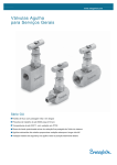
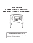
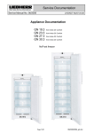
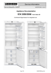
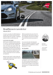
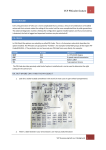
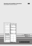
Service Documentation
After Sales Service International
Service Manual No. 04/2008
LHG/KDT-Ne/10.03.08
Appliance Documentation
K(es) 3670
K(es) 4270
from Index 20
Premium
from Index 20
Premium
Free-standing refrigerator
K 3670
K 4270
Page 1/24
04200800SM_gb.doc
Service Manual No. 04/2008
K(es) 3670 / 4270 from -20
Contents
1.0
2.0
3.0
3.1
4.0
4.1
Operating and control elements ...............................................................................................3
Functions at a glance.................................................................................................................4
Description of the appliance .....................................................................................................5
Sensor positions, schematic diagrams .........................................................................................5
Main components and their functions......................................................................................6
Electrical components and functions ............................................................................................6
4.1.1 General.................................................................................................................................................. 6
4.1.2 Refrigerator compartment ..................................................................................................................... 6
4.2 Refrigeration components and functions ......................................................................................7
4.2.1 General.................................................................................................................................................. 7
4.2.2 Refrigerator compartment ..................................................................................................................... 7
5.0 Assembly instructions / replacement of parts.........................................................................8
5.1 General.........................................................................................................................................8
5.1.1
5.1.2
5.1.3
5.1.4
5.1.5
Electronic unit of control panel .............................................................................................................. 8
Electronic power module....................................................................................................................... 9
Top door hinge .................................................................................................................................... 11
Bottom door hinge............................................................................................................................... 11
Door magnet........................................................................................................................................ 12
5.2 Refrigerator compartment...........................................................................................................13
5.2.1
5.2.2
5.2.3
5.2.4
5.2.5
6.0
6.1
7.0
7.1
7.2
7.3
7.4
7.5
8.0
8.1
Air sensor ............................................................................................................................................ 13
Evaporator sensor............................................................................................................................... 14
Fan ...................................................................................................................................................... 15
Refrigerator compartment light ........................................................................................................... 16
Pull-out rails vegetable drawer............................................................................................................ 18
Technical data ..........................................................................................................................19
Refrigerator compartment...........................................................................................................19
Service menu ............................................................................................................................20
Brief survey of service menu ......................................................................................................20
Demo mode ................................................................................................................................21
Panel test ...................................................................................................................................22
Sensor test (display of temperature) and door contact test........................................................23
Service mode..............................................................................................................................24
Error code, troubleshooting ....................................................................................................24
Table of error codes ...................................................................................................................24
Page 2/24
Service Manual No. 04/2008
K(es) 3670 / 4270 from -20
1.0 Operating and control elements
1
2
3
4
5
Symbol for ………
symbol lit = function activated
SuperCool
Ventilation
Alarm
Child lock
Menu
Demo mode
1
2
3
4
5
6
7
Refrigerator compartment
Ventilation
Fan function
Up
Setting button temperature higher
Down
Setting button temperature lower
Temperature display, function display
ON/OFF
ON/OFF button for refrigerator compartment
SuperCool
SuperCool function
Alarm
Alarm OFF button for audible alarm
Page 3/24
6
7
Service Manual No. 04/2008
K(es) 3670 / 4270 from -20
2.0 Functions at a glance
Control:
Electronic
Temperature display:
Actual value
Temperature range:
+2°C to +9°C
Temperature alarm:
Not present
Door alarm:
Audible
Fan:
Present
Defrosting:
Automatic
Interior light:
Present
Service menu:
Present
Compressor:
Standard
Solenoid valve
refrigeration circuit:
Not present
Page 4/24
Service Manual No. 04/2008
K(es) 3670 / 4270 from -20
3.0 Description of the appliance
The K(es) 3670 / 4270 is a free-standing refrigerator with fan.
The appliance is cooled by way of a freely suspended, rear wall evaporator. The appliance is regulated using an
air sensor and an evaporator sensor. A fan can be optionally activated.
3.1
Sensor positions, schematic diagrams
Interior light
Fan
Freely suspended
rear wall evaporator
Evaporator sensor
Air sensor
Fig. 3.1 / 2
Fig. 3.1 / 1
Page 5/24
Service Manual No. 04/2008
K(es) 3670 / 4270 from -20
4.0
Main components and their functions
4.1
Electrical components and functions
4.1.1
General
Electronic control system
Type:
Series 6 electronic control system
Components:
Control panel and power PCB
Compressor
Type:
Standard compressor.
Function:
ON: Evaporator sensor switch-on value.
Note: On-delay time (8 mins.) must have elapsed.
Off:
4.1.2
Air sensor switch-off value.
Refrigerator compartment
Electronic control system
Setting range:
+2°C to +9°C
Display range:
+2°C to 50°C
Functions
Ventilation:
Ventilation activated:
(see also under: Loads:
- Fan)
Fan runs in parallel with compressor.
Ventilation deactivated:
Fan is OFF. (Exception: SuperCool function activated)
SuperCool:
SuperCool activated:
Refrigerator compartment sets itself to +2°C for 6 hours. (Fan is ON)
SuperCool deactivated:
The refrigerator compartment sets itself to the set value.
Defrosting:
Automatic during compressor standstill phase.
Door alarm:
When:
If door is open, after 60 seconds.
Audible:
3 beeps.
Refrigerator
compartment air
sensor:
Position:
On the left, on a level with the lowest support rib.
Function:
- Switches the compressor OFF.
- Generates the display value.
Evaporator sensor:
Position:
On the back of the evaporator, on a level with the air sensor.
Function:
Switches compressor ON.
- Ends the defrosting phase.
Sensors
Page 6/24
Service Manual No. 04/2008
K(es) 3670 / 4270 from -20
Switch
Door switch:
Position:
In front panel
Type:
Reed PCB
Contact type: make contact
Function:
Activation via:
Magnet in the door, magnet is replaceable.
Switching signal when:
door closed:
interior light
OFF
door open:
interior light
fan
ON
OFF
Loads
Position:
Fan:
Beneath the ceiling of the appliance.
Function:
Ventilation
Compressor
ON
ON
ON
ON
ON
OFF
door
Fan
CLOSED
ON
OPEN
OFF
CLOSED
OFF
CLOSED/OP
OFF
ON/OFF
OFF
EN
e.g. if the ventilation is ON and the compressor is ON and the door is CLOSED,
then the fan is ON.)
During start-up the fan is activated only from an evaporator sensor temperature of
+5°C and colder.
Interior light of
refrigerator
compartment:
4.2
4.2.1
Position:
Ceiling
Function:
- Lights up as soon as door is opened.
- Is switched off after door has been open for 15 minutes.
Refrigeration components and functions
General
Compressor
Compressor:
4.2.2
Standard compressor
Refrigerator compartment
Evaporator
Type of design:
Rear wall evaporator
Type of installation:
Suspended freely.
Injection point:
Top centre
Flow sequence:
Top to bottom
Page 7/24
Service Manual No. 04/2008
K(es) 3670 / 4270 from -20
5.0 Assembly instructions / replacement of parts
5.1
General
5.1.1
Electronic unit of control panel
Covers:
Disengage covers at the marked points.
Fig. 5.1.1 / 1
Front panel:
Unlock locating lugs at the left and right of the front casing.
Fig. 5.1.1 / 2
Bus connector:
Disconnect and detach bus connector.
Front panel can be replaced only as a unit, PCB is not separately available!
Fig. 5.1.1 / 3
Page 8/24
Service Manual No. 04/2008
5.1.2
K(es) 3670 / 4270 from -20
Electronic power module
Attention:
Pull out the power plug!
Electronic power module cover:
- Disengage marked retaining clips.
- Swing out the cover at the bottom and lift for removal.
Fig. 5.1.2 / 1
Cable clip:
- Disengage the cable clip at the marked location.
Fig. 5.1.2 / 2
- Detach front PCB edge connector
- Release strain relief of supply cable.
- Disengage plug-in module at the right and left clip at draw it forwards for
removal.
Strain relief
Fig. 5.1.2 / 3
Page 9/24
Service Manual No. 04/2008
Plug-in module:
K(es) 3670 / 4270 from -20
- Detach rear PCB edge connector.
Fig. 5.1.2 / 4
Electronic power module:
- Disengage locating hooks on the holder for capacitors.
- Disengage electronic power module at the marked locations.
Fig. 5.1.2 / 5
Fig. 5.1.2 / 6
Page 10/24
Service Manual No. 04/2008
5.1.3
K(es) 3670 / 4270 from -20
Top door hinge
Turn hinge cover:
Disengage cover in marked direction and lift for removal.
Turn hinge:
Undo marked screws and remove turn hinge.
Fig. 5.1.3 / 1
Fig. 5.1.3 / 2
Fig. 5.1.3 / 3
Fig. 5.1.3 / 4
5.1.4
Bottom door hinge
Turn hinge cover:
Disengage the cover in the marked direction and remove it in a forward direction.
Bearing pin:
Retract the adjustable foot and press the bearing pin downwards. Then swing the door
out at the bottom and draw it out of the top bearing pin.
Fig. 5.1.4/ 1 Turn hinge cover
Fig. 5.1.4/ 2 Bearing pin
Page 11/24
Service Manual No. 04/2008
K(es) 3670 / 4270 from -20
Spring clip:
Depress the holder and remove the spring clip. Has to be transferred to the opposite
side if the door hinges are changed over.
Bottom bearing part:
Bottom bearing part has to be transferred if the door hinges are changed over.
Slot:
Screw can be transferred to the slot to faciltate door adjustment.
Spring clip
Slot
Bottom
b i
Fig. 5.1.4 / 4
Abb. 5.1.4/ 3 Spring clip
5.1.5
Door magnet
Magnet holder:
Depress marked locating lug and lever out the magnet holder in a forward direction.
Magnet
Fig. 5.1.5 / 1
Fig. 5.1.5 / 2
Page 12/24
Service Manual No. 04/2008
5.2
Refrigerator compartment
5.2.1
Air sensor
K(es) 3670 / 4270 from -20
Refrigerator compartment air sensor:
-
- Remove glass shelves and glass shelf supports.
Remove stopper.
Undo screw.
Unclip air sensor.
Undo lower screws holding the evaporator.
Press air sensor out, through the housing feed-through, behind the
evaporator.
Cut off air sensor cable and repair using repair kit (9590 088).
Air sensor
Stopper
Air sensor
Air sensor
Fig. 5.2.1 / 1
Fig. 5.2.1 / 2
Page 13/24
Service Manual No. 04/2008
5.2.2
K(es) 3670 / 4270 from -20
Evaporator sensor
Evaporator sensor:
-
Remove glass shelves and glass shelf supports.
Detach fan.
Undo screws holding the evaporator.
Press the evaporator down a little and fold to the left.
Draw the evaporator sensor out of the sensor pocket and press it
out through the housing feed-through.
Cut off the evaporator sensor cable and repair using repair kit
(9590 088).
Evaporator
Fig. 5.2.2 / 2
Evaporator sensor
Fig. 5.2.2 / 1
Page 14/24
Service Manual No. 04/2008
5.2.3
K(es) 3670 / 4270 from -20
Fan
Fan:
-
Undo fastening screws of the fan (see Fig. 5.2.3 / 1).
Pull off connecting cable (see Fig. 5.2.3 / 2).
Disengage locating lugs of the fan cover (see Fig. 5.2.3 / 2) and remove fan cover
in a forward direction.
Lift fan motor out of the fan housing.
Locating lugs
Fig. 5.2.3 / 2 Fan cover
Fig. 5.2.3 / 1 Fan
Fan casing
Fan motor
Fan cover
Fig. 5.2.3/ 3 Fan components
Page 15/24
Service Manual No. 04/2008
5.2.4
K(es) 3670 / 4270 from -20
Refrigerator compartment light
Unlock and remove faceplate for ceiling light.
Faceplate for ceiling
light
Fig. 5.2.4 / 1
Pull out glass plate in a forward direction.
Fig. 5.2.4 / 2
Undo fastening screws and fan fastener (see
5.2.3).
Fig. 5.2.4 / 3
Fold down the light housing.
Fig. 5.2.4 / 4
Page 16/24
Service Manual No. 04/2008
K(es) 3670 / 4270 from -20
Disengage the reflector plate.
Info: The reflector plate holds the lampholder
cover.
Fig. 5.2.4 / 5
Remove lampholder cover
Fig. 5.2.4 / 6
Fig. 5.2.4 / 7
Page 17/24
Service Manual No. 04/2008
K(es) 3670 / 4270 from -20
5.2.5 Pull-out rails vegetable drawer
Pull-out rail:
- Depress lock and press rail to the rear (Fig. 5.2.5 / 1).
Fig. 5.2.5 / 1
Fig. 5.2.5 / 2
Similar to product
Similar to product
Fig. 5.2.5 / 3
Page 18/24
Service Manual No. 04/2008
K(es) 3670 / 4270 from -20
6.0 Technical data
6.1
Refrigerator compartment
Sensor values:
Air sensor and evaporator sensor
Temperature °C
Resistance value kOhm
+35
+30
+25
+20
+15
+10
+5
0
-5
-10
-15
-20
-25
-30
-35
3.1
3.8
4.7
5.9
7.3
9.3
11.9
15.3
19.8
25.9
34.1
45.3
60.8
82.3
112.8
Interior light:
Wattage:
Voltage:
Socket:
2 x 25 watts
230
volts
E14
Fan:
Wattage:
Voltage:
Speed:
7.5 watts
230 volts (50/60Hz)
1650 rpm Direction of rotation:
Page 19/24
left (as viewed onto shaft)
Service Manual No. 04/2008
7.0
K(es) 3670 / 4270 from -20
Service menu
The service menu may be used by service technicians only.
Press "Up" + "ON/OFF" simultaneously for about 5 seconds
Activation of service menu:
If the service menu is activated, then "MENU" flashes in the display.
7.1
Brief survey of service menu
Service menu
Menu
Demo mode
Sensor test
Service mode
Selection of functional part
1x SC Demo mode ON
1x SC
Å Up or Down button Æ
Panel test
Operati
Operati
Submenu
on
on
Demo mode OFF
1x SC Press sensor buttons, door sensor
1x SC
1x SC
1x SC
Page 20/24
1x SC
Up-/
Down
button
È/Ç
1x SC
Up-/
Down
button
È/Ç
: Refrigerator compartment air
sensor
: Refrigerator compartment
evaporator sensor
: Refrigerator compartment
door contact
: All OFF
: Compressor ON
: Light ON
: Fan
Service Manual No. 04/2008
7.2
Demo mode
Step
Display
K(es) 3670 / 4270 from -20
Operation
Display following
operation
SC = SuperCool
Start service menu -- Demo mode ON -1
2
3
Actual value
flashes
Static
Press
"Up" and "ON/OFF"
simultaneously for 5
seconds
Press "SC" once
Press "SC" once
flashes
Service menu active
Demo mode selected
Static
Demo mode ON
selected
Set value
and "Demo"
Actual value and "Demo"
2
Press
"Up" and "ON/OFF"
simultaneously for 5
seconds
Press "SC" once
flashes and "Demo"
3
Demo mode ON
SC = SuperCool
Start service menu -- Demo mode OFF-1
Testing option / Info
Press "SC" once
static and "Demo"
flashes and "Demo"
Service menu active
Demo mode selected
static and "Demo"
Demo mode OFF
selected
Actual value
Demo mode OFF
The text "Demo" in the display informs about the activated demo mode.
Demo mode can be deactivated only via service menu, not by OFF/ON or disconnection from the supply.
Operation switches to the mode wanted, demo mode or normal mode as soon as "SuperCool" has been
actuated.
Page 21/24
Service Manual No. 04/2008
7.3
Panel test
Step
Display
K(es) 3670 / 4270 from -20
Operation
Display following
operation
Service menu start
1
Actual value
Testing option / Info
SC = SuperCool
Press
"Up" and "ON/OFF"
simultaneously for 5
seconds
flashes
Service menu active
Panel test
-- test of sensor buttons, display elements, door sensor and beep -2
3
flashes
flashes
Press "Up" once
Press "SC" once
Press "SC" once
4
flashes
Static
All symbols/segments
Static
5
End
All symbols/segments
Door closed/open
and press all buttons one
- Beep for 2 seconds
after the other
- Appliance switches
OFF
(confirmed by beep in
each case)
Panel test selected
Panel test
activated
Display elements/
More symbols are
displayed than the
respective electronic
control system uses!
After the last button
has been pressed, a
beep sounds for 2
seconds, provided the
test was successful.
Panel test cannot be ended in step 2, for example, it has to be performed in full.
Should a button/sensor be defective, no beep sounds for 2 seconds and the appliance does not
switch OFF.
The appliance then has to be unplugged and plugged back in again.
Page 22/24
Service Manual No. 04/2008
7.4
K(es) 3670 / 4270 from -20
Sensor test (display of temperature) and door contact test
Step
Display
Operation
Display following
operation
Testing option / Info
Service menu start
1
Actual value
SC = SuperCool
Press
"Up" and "ON/OFF"
simultaneously for 5
seconds
flashes
Service menu active
Sensor test and door contact test (sensor values without offset, appliance in control mode)
2
3
flashes
flashes
4
Press "Up" twice
Press "SC" once
Press "SC" once
Static
End
5
flashes alternately with
sensor temperature
Press "Up" once
6
flashes alternately with
sensor temperature
Press "Up" once
flashes
Sensor test mode
selected
Static
Sensor test mode
activated
flashes alternately with
sensor temperature
Refrigerator
compartment air
sensor
flashes alternately with
sensor temperature
Refrigerator
compartment
evaporator sensor
flashes alternately with
k
or
Door contact
(cL=door closed,
oP=door open)
Press "ON/OFF" once: Return to level 2
. No further points selectable with this appliance.
Press "ON/OFF" twice: Return to level 1
. Points:
,
,
,
selectable
Press "ON/OFF" three times: Return to normal/control mode
Page 23/24
Service Manual No. 04/2008
7.5
K(es) 3670 / 4270 from -20
Service mode
Step
Display
Operation
Display
following
operation
Testing option / Info
Service menu start
1
SC = SuperCool
Actual value
Press
"Up" and "ON/OFF"
simultaneously for 5
seconds
Service menu active
flashes
Service mode
-- testing electric loads-2
flashes
3
flashes
7Æ4
Static
5
Static
6
Static
4Å7
Power
input
Press "Up" 3 times
Press "SC" once
Press "SC" once
Press "Up" once
Press "Up" once
Service mode selected
flashes
Service mode activated
Static
Static
Static
Static
Press "Up" once
Static
All OFF
1.9 W
Compressor ON
--
Light ON
48 W
Fan
7.5 W
Static
Press "ON/OFF" once: Return to level 2 :
. No further points selectable with this appliance.
Press "ON/OFF" twice: Return to normal/control mode.
End
8.0 Error code, troubleshooting
8.1
Table of error codes
Error code
Defective component
Emergency mode
F1
Refrigerator compartment air sensor
Compressor ON 10 mins., OFF 22 mins.
F2
Refrigerator compartment evaporator
sensor
Compressor ON 10 mins., OFF 22 mins.
Page 24/24