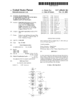
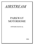
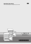
1
Service Information
After Sales Service International
Service Information No. 100/2004
LHG/TKD-Ne/20.12.04
Appliance documentation
Built-in Refrigerator
24’’ width
Version 137
RI 1400
- with Inverter-
R 1400
- with Inverter- in stainless steel-
Page 1/14
100200400SI_gb
Service Information No.100/2004
LHG/TKD-Ne/20.12.04
Contents
1.0
Extract from the user’s manual
page
3-5
1.1 The appliance at a glance
page
3-4
1.2 Operation and control elements
page
5
2.0
Functions at a glance
page
6
3.0
Description of the appliance (in brief)
page
6
4.0
Control and functional parts
page
7
4.1 Refrigerator
page
7
Cooling circuit
page
7
5.1 Refrigerator
page
7
Special features
page
8
6.1 VCC compressor
page
8
Installation instructions
page
9-11
7.1 Refrigerator-Fan
page
9
7.2 Refrigerator-Evaporator sensor
page
10
7.3 Electronics disassembly
page
11
Technical specifications
page
12
8.1 Refrigerator
page
12
Service menu
page
13
9.1 Demo mode “d1” or “d0”
page
13
9.2 Service mode “L”
page
13
page
14
5.0
6.0
7.0
8.0
9.0
10.0 Error code table
Page 2/14
Service Information No.100/2004
1.0
1.1
LHG/TKD-Ne/20.12.04
Extract from the user’s manual
The appliance at a glance
Page 3/14
Service Information No.100/2004
LHG/TKD-Ne/20.12.04
Page 4/14
Service Information No.100/2004
1.2
LHG/TKD-Ne/20.12.04
Operation and control elements
Page 5/14
Service Information No.100/2004
2.0
Functions at a glance
LHG/TKD-Ne/20.12.04
(X = available, O = not available)
Control:
X electronics
O thermostat
Temperature display:
O analogue
X digital
Fan:
X
Defrosting:
Lighting:
O manual
X automatic
X Refrigerator
SuperCool:
X
Service menu:
X start by button combination
O start by test jack
Cooling technology:
X
3.0
Refrigerator
automatic. (33°F for 6h)
1 VCC compressors
Description of the appliance (in brief)
The R(I) 1400 is a built-in refrigerator with switch-controlled ventilation and SuperCool functions. The
appliance is controlled via an evaporator sensor and is equipped with a VCC compressor.
Page 6/14
Service Information No.100/2004
4.0
4.1
LHG/TKD-Ne/20.12.04
Control and functional parts
Refrigerator
Electronics:
Magnetec series no. 3 electronics, control panel PCB and power PCB.
The microcontroller is situated on the power PCB.
Display range:
33°F to 49°F
Setting range:
+33°F to +49°F
Interior light:
Left inner side in the refrigerator. Switches off after door is open for 15 mins.
Air sensor:
Function:
- Switches the compressor on/off.
Position:
- In evaporator pocket on rear side of evaporator.
Sensor error: - Display F 2, audible warning 3 warning tones.
Emergency mode: - Compressor and fan switch over to a pre-programmed
switch mode: 10 mins. ON, 40 mins. OFF.
SuperCool:
A higher cooling rate is achieved. The SuperCool function is active for a duration
of 6 hours, the appliance adjusts to a temperature of +33°F (+1°C).
Fan
Top centre of refrigerator compartment. Can be switched on and off in the control
panel.
( 1°C to 9°C ).
(+1°C to +9°C).
With activated ventilation function :
•
Ventilator is in operation as soon as the compressor is on.
•
Switches off when door is opened (Reed switch).
Defrosting:
- in normal mode:
- automatically during the standstill phase of the compressor
- after continuous compressor operation:
- after continuous compressor operation of 4 hours.
The minimum downtime after continuous operation is 40 mins.
Compressor:
VCC-Compressor
Continuous operation limit: 4 hrs.
-> After continuous operation of the compressor of 4 hours, a minimum
compressor downtime of 40 minutes follows.
Reconnection delay: 8 mins.
5.0
5.1
Cooling circuit
Refrigerator compartment
Evaporator:
Freely suspended rear wall evaporator. Evaporator sensor can be
replaced separately.
Injection point / flow sequence:
Injection of coolant in refrigerator compartment evaporator top left /
Condenser -> frame heating -> evaporator
Compressor:
VCC compressor.
Coolant:
R134a
Page 7/14
Service Information No.100/2004
6.0
Special features
6.1
VCC compressor
LHG/TKD-Ne/20.12.04
The drop-in electronic inverter automatically sets the speed of the VCC compressor (variable capacity
compressor). No frequency signal is required here.
•
Compressor with 4 different speed steps (1600 / 1900 / 3000 / 3600 rpm).
•
The electronic inverter is directly attached to the compressor. The electronic inverter controls the compressor with a pulse-wide modulated square wave voltage.
•
To set the speed, the electronic inverter evaluates the operation time of the compressor.
Attention; danger of destruction
The compressor may only be operated via the inverter
Inverter
6.1.1
Speed control VCC compressor
The electronic inverter receives the ON-OFF signal via the power PCB. The speed of the compressor is
automatically calculated by the electronic inverter.
The speed is calculated based on the operating time of the compressor.
•
On start-up, the compressor operates at a speed of 3000 rpm.
•
Speed increase during compressor operation by 1 step
if the operating time is longer than 70 minutes.
•
No change in speed with next start-up
if the operating time was 40 to 70 minutes.
•
Speed reduction with next start-up if the operating time was shorter than 40 minutes.
Page 8/14
Service Information No.100/2004
7.0
7.1
LHG/TKD-Ne/20.12.04
Assembly instructions
Refrigerator compartment fan
The fan is inserted in the plastic housing with rubber buffers. The supply cable is fitted with a detachable
plug.
The fan housing is fixed to the ceiling
of the appliance with two screws
(see Fig. 7.1.1).
Fig. 7.1.1: Position of screws
1 Plug contact fan supply cable
2 Remove air guide plate
upwards
1
2
Fig. 7.1.2: View inside the fan housing
Page 9/14
Service Information No.100/2004
7.2
LHG/TKD-Ne/20.12.04
Refrigerator compartment evaporator sensor
The evaporator sensor is inserted in a sensor pocket on the rear side of the evaporator.
1
1
1. Remove glass shelves.
2. Disassemble fan, see 7.1.
3. Undo evaporator fixing screws 1 .
1
1
Fig. 7.2.1: Disassembly of rear wall evaporator
Turn out rear wall evaporator on the
right-hand side (the suction pipe bushing
is situated on the left).
1 Refrigerator compartment evaporator sensor.
2 Sensor pocket on the back of the evaporator.
1
2
Fig. 7.2.2: Position of evaporator sensor
Page 10/14
Service Information No.100/2004
7.3
LHG/TKD-Ne/20.12.04
Electronics disassembly
Remove covers and undo Torx screws.
Carefully remove the electronics housing and
disconnect the wire connectors.
Release the lips and remove the board bracket from
the front panel.
Release the lips and remove the power board bracket.
Carefully release the lips (arrows).
Page 11/14
Service Information No.100/2004
8.0
8.1
LHG/TKD-Ne/20.12.04
Technical specifications
Refrigerator
Lighting:
Output:
Voltage:
Fitting:
Fan:
Output:
6 Watts
Voltage:
100 Volts (AC)
Resistance:
131 Ohms
Revolution:
1700 rpm
evaporator sensors
Sensor values:
25 Watts
115 Volts (AC)
E14
Temperature
[°C]
+35
+30
+25
+20
+15
+10
+5
0
-5
-10
-15
-20
-25
-30
-35
Temperature
[°F]
+95
+86
+77
+68
+59
+50
+41
+32
+23
+14
+5
-4
-13
-22
-31
Page 12/14
Resistance value
[kOhm]
3,1
3,8
4,7
5,9
7,3
9,3
11,9
15,3
19,8
25,9
40,4
45,3
60,8
82,3
82,3
Service Information No.100/2004
9.0
LHG/TKD-Ne/20.12.04
Service menu
The service menu may only be used by after-sales service technicians.
°F
49
45
41
37
33
9.1
Demo mode
°C
9
7
5
3
1
“d1” or “d0”
•
Set control knob to 0. Press SuperCool (SC) for three seconds and turn the control knob to the
right.
•
SC flashes, you are in the service menu.
•
Turn control knob until the 45°F-LED (7°C) is lit.
•
Press SC, demo mode is activated, the service menu is ended.
Attention: The demo mode can only be deactivated by switching off at the mains.
9.2
Service Mode
•
Set control knob to 0. Press SC for three seconds and turn the control knob to the right.
•
SC flashes, you are in the service menu.
•
Turn control knob until the 41°F-LED (5°C) is lit.
•
Press SC, SC flashes. 49°F-LED (9°C) is lit.
The appliance is in service mode.
•
Close and open refrigerator compartment door. 49° and 45°F-LED (9° and 7°C) are lit.
The appliance is no longer in service mode.
•
Set control knob to 0. 49° and 45°F-LED (9° and 7°C) go out.
41°, 37° and 33°F-LED (5°, 3° and 1°C) are lit.
•
Turn control knob to the right. 41°, 37° and 33°F-LED (5°, 3° and 1°C) go out.
SC-LED and ventilation-LED are lit.
•
Press SC, SC-LED and ventilation-LED go out.
49° and 45°F-LED (9° and 7°C) are lit.
•
Press ventilation; 49° and 45°F-LED (9° and 7°C) go out.
41°, 37° and 33°F-LED (5°, 3° and 1°C) are lit.
•
Interior light switches off after 3 secs. (all consumers are off),
49°F-LED (9°C) is lit, SC-LED flashes.
Press SC.
•
45°F-LED (7°C) is lit and SC flashes. The compressor switches on
(Attention: the coil protection switch may be triggered).
Press SC.
•
33°F-LED (1°C) is lit and SC flashes. Compressor switches off. Interior light switches on.
Press SC.
•
41°F-LED (5°C) is lit and SC flashes. Interior light switches off. Fan switches on.
•
Set control knob to 0, the service menu is ended.
Page 13/14
Service Information No.100/2004
LHG/TKD-Ne/20.12.04
10.0 Error code table
Error code
SC- and 37°F (3°C)-LED flash
+ alarm tone (3 signal tones)
Defective component
Refrigerator compartment
evaporator sensor
Page 14/14
Emergency mode
Compressor 10 mins. on and 40 mins. off