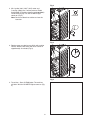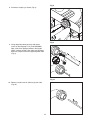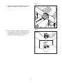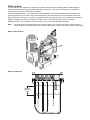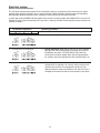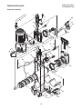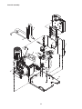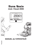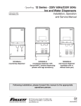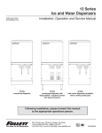
1
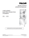
HCD1400R, HCD1400N Icemakers
Order parts online
www.follettice.com
Operation and Service Manual
After Serial Number C20000
208264
tion
Plate
tifica
ule
k Mod
Stoc No.
ule
Mod
uct
Prod No.
ice
Serv
ia
lvan
nsy
Pen NO
ton
T
Eas
PAR
Iden
ION
GLE
SIN SE
PHA
HZ
NO
IAL
TED
RAT
SER
TEC E
RPO
RG
CO
TS
Y PROCHA
VOL
E
ALL
SID
RM
THE
LOW
F
SOR
NS
RES
PS
MP
D AM CO
R
TOR
C
E
MO
R
S
NT
H SID
AMP
ERA
HIG
S
RIG
RE
AMP
REF
SSU
PRE
CITY
IGN
AMPA
UIT
DES
SIZE
CIRC
DEL
OZ
PSIG
E IN
MAD USA
THE
MO
UL
L LOA
UL
FUL
CH
BRAN
MIN.
CH
UIT
FUSE
CIRC
BRAN
MAX.
Following installation, please forward this manual
to the appropriate operations person.
801 Church Lane • Easton, PA 18044, USA
Toll free (800) 523-9361 • (610) 252-7301
Fax (610) 250-0696 • www.follettice.com
00171603R01
Follett Corporation
Equipment Return Policy
Follett equipment may be returned for credit under the following conditions:
1.
The equipment is new and unused.
2. A return authorization number has been issued by customer service within 30 days after shipment.
3. Follett receives the equipment at the factory in Easton, PA within 30 days after issuance of the return authorization number.
4. The equipment must be returned in Follett packaging. If the packaging has been damaged or discarded, Follett will forward,
at the customer’s expense, new packaging.
Note:
Return freight charges are the responsibility of the customer. If equipment is returned and is damaged because of
improper packaging, Follett Corporation will not be held responsible.
Credit will be issued when:
The equipment has been inspected by Follett and deemed suitable to be returned to stock.
Note:
A 15% restocking charge will be deducted from the credit. If the cost to return the product to stock exceeds 15%, the
actual cost will be deducted.
2
Table of contents
Welcome to Follett Corporation
Specifications
Operation
Cleaning, weekly exterior care
Cleaning, semi-annual evaporator cleaning
Service
Icemaker operation
Water system
Electrical system
Normal control board operation
Test points
Time delay and self-flushing jumpers
Error faults
Hard errors
Soft errors
Relay output indication
Compressor/refrigerant solenoid output
Wiring diagram, evaporator unit
Wiring diagram, condenser unit
Gearmotor data
Mechanical system
Evaporator disassembly
Evaporator reassembly
Refrigeration system
Condenser unit operation
Refrigerant pressure data
Refrigerant charges
Refrigeration system diagram
Refrigerant replacement requirements
Evacuation
Ambients (evaporator unit)
Ice capacity test
Bin full detection system
Troubleshooting
Replacement parts
3
4
5
7
7
7
12
12
13
14
14
15
15
15
15
15
15
15
16
17
17
18
18
20
23
23
23
23
24
25
25
25
25
26
27
30
Welcome to Follett
Follett equipment enjoys a well-deserved reputation for excellent performance, long-term reliability and
outstanding after-the-sale support. To ensure that this equipment delivers the same degree of service, we ask
that you review the installation manual (provided as a separate document) before beginning to install the unit.
Our instructions are designed to help you achieve a trouble-free installation. Should you have any questions or
require technical help at any time, please call our technical service group at (800) 523-9361 or (610) 252-7301.
Before you begin
After uncrating and removing all packing material, inspect the equipment for concealed shipping damage. If damage
is found, notify the shipper immediately and contact Follett Corporation so that we can help in the filing of a claim,
if necessary.
Check your paperwork to determine which model you have. Follett model numbers are designed to provide information
about the type and capacity of Follett equipment. Following is an explanation of the different model numbers in the
1400 series.
Horizon Series Icemaker Model Number Configurations
HC
Icemaker
Voltage
C 208-230/60/1
HC Horizon
(self-contained only)
Chewblet®
D Low side 115/60/1
HM Horizon
Condensing unit
MINI
208-230/60/1
Chewblet
(remote condensing only)
E 230/50/1
D
1400
R
Series
1000 up to
1036 lbs
(471kg)
1400 up to
1450 lbs
(658kg)
V
S
Condenser
A
W
R
N
Air-cooled, self-contained
Water-cooled, self-contained
Air-cooled, remote condensing unit
Air-cooled, no condensing unit for
connection to parallel rack system
(self-contained only)
Application
Configuration
S Satellite-fill™
V Vision™
T Top-mount
H Harmony™
B Ice storage
bin
J Drop-in
M Ice Manager†
diverter valve
system
† Ice Manager Diverter Valve Systems can be used to fill any two of these bins or dispensers with a single ice machine.
Chewblet is a registered trademark of Follett Corporation, registered in the US.
CAUTION
• Moving parts. Do not operate with front cover removed.
• Hot parts. Do not operate with cover removed.
• To reduce risk of shock, disconnect power before servicing.
• Most ice machine cleaners contain citric or phosphoric acid, which can cause skin irritation. Read caution
label on product and follow instructions carefully.
• Ice is slippery. Maintain counters and floors around dispenser in a clean and ice-free condition.
• Ice is food. Follow recommended cleaning instructions to maintain cleanliness of delivered ice.
4
Specifications
Electrical
Separate circuit and equipment ground required.
Evaporator unit
Standard electrical – 115/60/1
Maximum fuse – 15 amps
Amperage – 6 amps
Condenser unit
Standard electrical – 220V, 60Hz, 1 phase
Maximum fuse – 40 amps
Amperage – 21.4 amps
Evaporator plumbing
3/8" OD push-in water inlet
3/4" MPT
Notes: 3/4" vented drain line must slope a minimum of 1/4" per foot (6mm per 30.4cm run).
Drain to be hard piped and insulated.
Water shut-off recommended within 10 feet (3m).
Follett recommends installation of Follett water filter system (part# 00130286) in icemaker
inlet water line.
Ambient
Evaporator unit
Air temperature
Water temperature
Water pressure
100˚F/38˚C max.
90˚F/32˚C max.
70 psi max. (483 kPa)
50˚F/10˚C min.
45˚F/7˚C min.
10 psi min. (69 kPa)
120˚F/49˚C max.
– 20˚F/-29˚C min.
Condenser unit
Air temperature
Refrigeration
3/8" liquid line
5/8" suction line
Note: Rack system installations require a reserve capacity of 10,000 BTU/hr at
0˚F (-18˚C) evaporator temperature.
Evaporator pressure regulator (not supplied) is required.
Weight
Ice production
Evaporator unit
Icemaker capacity/24 hrs.
Ambient Air Temperature F/C
190 lbs (88kg)
Inlet Water Temperature F/C
Condenser unit
385 lbs (175kg)
5
F
C
50
10
60
16
70
21
80
27
90
32
60
16
1231
559
1182
537
1146
520
1110
504
1074
488
70
21
1206
548
1157
525
1121
509
1085
493
1049
476
80
27
1163
528
1127
512
1091
495
1055
479
1019
463
90
32
1128
512
1088
494
1048
476
1008
458
968
440
100
38
1098
499
1055
479
1012
460
969
440
926
421
lbs
kg
lbs
kg
lbs
kg
lbs
kg
lbs
kg
Dimensions and clearances
Entire front of icemaker must be clear of obstructions/connections to allow removal.
1" (26mm) clearance above icemaker for service.
1" (26mm) minimum clearance on sides.
Front View
Side View
Back View
Ice transport tube connection
Air exhaust
both sides
21.28" (541mm)
19.3" (491mm)
L2
NEMA 5-15
right angle
23.50"
(597mm)
G
L1
14.47"
(368mm)
5/8" suction line
3/8" liquid line
Easton Pennsylvania
CORPORATION
MODEL
SERIAL NO
FULL LOAD AMPS
6.95"
(177mm)
2.53"
(65mm)
PART NO
VOLTS
HZ
SINGLE
PHASE
MOTOR COMPRESSOR THERMALLY PROTECTED
REFRIGERANT
CHARGE
OZ
LOW SIDE
DESIGN PRESSURE HIGH SIDE
PSIG
208264
Stock Module Identification Plate
Module No.
Product
MIN. BRANCH CIRCUIT AMPACITY
AMPS
MAX. BRANCH CIRCUIT FUSE SIZE
AMPS
UL
UL
R
R
NSF
MADE IN
THE USA
C
Service No.
21.05" (535mm)
23.77" (604mm)
3/8" OD push-in
water inlet
2.87
(73mm)
2.5" (64mm)
15.69" (399mm)
3/4" MPT drain
Condensing Unit
Front View
Condensing Unit
Side View
Condensing Unit
Back View
26.54"
(675mm)
40.7"
(1034mm)
31.25"
(794mm)
6
Power connections
3/8" OD high pressure line (liquid line)
5/8" OD low pressure line (suction line)
1.81
(46mm)
Operation
Cleaning and preventive maintenance (all models)
Note:
Do not use bleach to sanitize or clean the icemaker.
Preventive maintenance
Periodic cleaning of Follett’s icemaker system is required to ensure peak performance and delivery of clean,
sanitary ice. The recommended cleaning procedures that follow should be performed at least as frequently as
recommended, and more often if environmental conditions dictate.
Cleaning of the icemaker system, in most cases, should be performed by your facility’s maintenance staff or a
Follett authorized service agent. Regardless of who performs the cleaning, it is the operator’s responsibility to
see that this cleaning is performed according to the schedule below. Service problems resulting from lack of
preventive maintenance will not be covered under the Follett warranty.
Weekly exterior care
The exterior may be cleaned with a stainless cleaner such as 3M Stainless Steel Cleaner & Polish or equivalent.
Semi-annual evaporator cleaning (every 6 months)
WARNING
• Wear rubber gloves and safety goggles (and/or face shield) when handling ice machine cleaner or sanitizer.
CAUTION
• Use only Follett approved SafeCLEAN™ Cleaner (part #00132001) and NU-CALGON IMS-II SANITIZER.
• Do not mix Cleaner and Sanitizer solutions together.
• DO NOT USE BLEACH.
• It is a violation of Federal law to use these solutions in a manner inconsistent with their labeling.
• Read and understand all labels printed on packaging before use.
Note: Complete procedure for cleaning an sanitizing MUST be followed. Ice must be collected for 10
minutes before putting ice machine back into service.
Fig. 1
1. To clean – Remove cover. Press the CLEAN
button. The machine will drain. Wait for the LO
WATER light to come on (Fig. 1).
LO WATER
Note: For Ice Manager diverter valve
application, refer to manual # for icemaker and
diverter valve cleaning process.
CL
EA
N
7
Fig. 2
2. Mix 1 gallon (3.8L) 120˚F (49˚C) water and
7 ounces (198g) (one 7 ounce packet of Follett
SafeCLEAN ice machine cleaner, part#-00132001).
Locate cleaning cup. Fill until HI WATER light
comes on (Fig. 2).
Note: Do not use bleach to sanitize or clean the
icemaker.
HI WATER
Fig. 3
3. Replace cover on cleaning cup. Wait until machine
restarts. Machine will clean, then flush 3 times in
approximately 12 minutes (Fig. 3).
12
Fig. 4
4. To sanitize – Press CLEAN button. The machine
will drain. Wait for LO WATER light to come on (Fig.
4).
8
Fig. 5
5. Mix 1 gallon 120˚F (49˚C) water and 1.6 ounces
(48ml) NU-CALGON IMS-II SANITIZER. Fill until
HI WATER light comes on (Fig. 5).
Note: Do not use bleach to sanitize or clean the
icemaker.
HI WATER
Fig. 6
6. Replace cover on cleaning cup. Wait until machine
restarts. Machine will sanitize, then flush 3 times in
approximately 12 minutes (Fig. 6).
12
Fig. 7
7. To clean transport tube – Press power switch OFF
(Fig. 7).
9
Fig. 8
8. Disconnect coupling as shown (Fig. 8).
Fig. 9
9. Using disposable food service grade gloves,
insert dry Sani-Sponge™ (kit part# 00132068).
Next,-insert Sani-Sponge soaked in Nu-Calgon
IMS-II sanitizer solution. Push both Sani-Sponges
down ice transport tube with supplied pusher tube
(Fig. 9).
(40 16"
7m
m)
1
2
3
Fig. 10
10. Remove and discard 16" (407mm) pusher tube
(Fig. 10).
10
Fig. 11
11. Reconnect coupling. Press power switch ON. Ice
pushes Sani-Sponges through tube (Fig. 11).
Fig. 12
12. Place a sanitary (2 gallon or larger) container in
bin or dispenser to collect Sani-Sponges and ice
for 10 minutes. Collect 5.5 lbs of ice from unit.
Discard ice and Sani-Sponges (Fig. 12).
11
Service
Icemaker operation (all models)
Follett’s icemaker consists of five distinct functional systems covered in detail as follows:
• Water system
• Electrical control system
• Mechanical assembly
• Refrigeration system
• Bin full
The Horizon icemaker overview
The Follett Horizon icemaker uses a horizontal, cylindrical evaporator to freeze water on its inner surface. The
refrigeration cycle is continuous; there is no batch cycle. The evaporator is flooded with water and the level is
controlled by sensors in a reservoir. A rotating auger (22 RPM) continuously scrapes ice from the inner wall of the
evaporator. The auger moves harvested ice through the evaporator into an ice extrusion canal. The ice is forced
through a restrictive nozzle that squeezes out the water and creates the Chewblet. The continuous extrusion process
pushes the Chewblets through a transport tube into a dispenser or bin.
A solid state PC board controls and monitors the functionality of the ice machine. In addition to sequencing electrical
components, the board monitors various operational parameters. A full complement of indicator lights allows visual
status of the machine's operation. Additionally, the PC board controls the self-flushing feature of the icemaker. The
evaporator water is periodically drained and replenished to remove minerals and sediment.
A unique “bin full” detection system is incorporated in the Horizon icemaker. A switch located at the ice discharge
port of the machine detects the position of the transport tube. When the bin fills up with ice, the transport tube
moves out of the normal running position, and the switch turns the ice maker off. A domed housing at the end of the
transport tube contains the ice extrusion loads during shut down.
Harvest system diagram
ice
transport
tube
water
inlet
compression
nozzle
auger
12
Water system
The water level in the evaporator is controlled by a feed solenoid and level detecting sensors. Referencing the
diagram below, water sensing rods extend down into the reservoir at the end of the evaporator assembly. The
system works via electrical conductivity as follows:
One of the longest probes is a common. When water is between any of the other probes and the common, the
PC board will sense the activation. During normal operation, the water level rises and falls between the Normal
High and Normal Low sensors. As water is consumed to make ice, the level will fall until the Normal Low sensor is
exposed, triggering the water feed solenoid on. Water will fill until the Normal High sensor is activated.
Additional sensors are incorporated in the reservoir for alarm and cleaning/flushing conditions.
Note:
The potable water dissolved solids content must be greater than 10 ppm for the water control system to
function properly. If using reverse osmosis water filtration system, ensure T.D.S level is greater than 10 ppm.
Water system diagram
Water level diagram
13
Normal HI
Alarm LO
Common
Normal LO
Normal
operating
range
Electrical system
Normal control board operation
The PC board indicator lights provide all the information necessary to determine the machine’s status. Green
indicator lights generally represent “go” or normal operation; Yellow indicators represent normal off conditions;
Red indicators generally represent alarm conditions, some of which will lock the machine off.
A green light labeled POWER indicates power to the machine. A flashing green light labeled CPU is normal and
indicates that the Central Processing Unit “heart beat” is working. All other normal operation status indicators are
covered as follows:
Ice machine disposition
Legend:
OFF
ON or OFF
FLASHING
1.
POWER
LOW BIN
AUGER ON
REFRIG ON
TIME DELAY
CLEANING
PURGE
SERVICE
HI AMPS
DRAIN CLOG
HI WATER
LO WATER
CPU
2. Ice machine is not making ice.
POWER
LOW BIN
AUGER ON
REFRIG ON
TIME DELAY
CLEANING
PURGE
SERVICE
HI AMPS
DRAIN CLOG
HI WATER
LO WATER
3. Ice machine is not making ice.
CPU
Normal running.
POWER
LOW BIN
AUGER ON
REFRIG ON
TIME DELAY
CLEANING
PURGE
SERVICE
HI AMPS
DRAIN CLOG
HI WATER
LO WATER
Ice machine is making ice.
CPU
1.
ON
Operating conditions
2. Normal time delay. When the bin fills with ice, the LOW BIN
light goes out and the refrigeration and auger drive systems
immediately shut down. The TIME DELAY light comes on,
initiating the time delay period. When the time delay expires,
the machine will restart provided that the LOW BIN light is on.
3. Normal purge indicator. After a selected period of ice
making time has elapsed (1 or 2 hours), the ice machine will
automatically self-flush. The refrigeration system will shut
down but the gear motor will continue to run. After the flush is
complete the machine will refill and start without a time delay.
14
Test points:
The Horizon PC board incorporates on-board test points that can be used to determine various electrical outputs.
The test point holes allow a standard probe to be inserted for quick voltage measurement.
Error faults:
The Horizon PC board monitors various operating parameters including high pressure, auger gearmotor
amperage limits, clogged drain, and high and low water alarm conditions. There are two types of errors namely
“hard” or “soft”. A hard error is one that shuts the machine off and will not allow restart until the reset button is
pressed. Even cycling power will not reset a hard error. A soft error can either be automatically reset should the
condition rectify, or if power is cycled. Should an error occur, consult the troubleshooting guide in this manual or
a Follett service technician. Note: there are two types of LO WATER and HI AMPS errors as listed below.
Soft errors:
HI AMPS: The PC board monitors the amperage of the auger motor. Should the gear motor experience current
draw above the 8.4 amps limit the machine will shut down and the TIME DELAY, HI AMP, and SERVICE LED’s
will be illuminated. After the time delay the machine will restart and the TIME DELAY, HI AMP, and SERVICE
LED’s will clear.
LO WATER: During operation, the water level cycles between the normal low and normal high sensors. Should
the water be shut off to a running machine, a soft error will occur. The error sequence is as follows: During
operation, the water level falls to the normal low sensor, and when it does the water feed solenoid is energized. If
water is not detected at the normal low sensor within 120 seconds, a soft error will occur. The machine will shut
down, but the water feed solenoid will remain energized. Should water return, it will fill to the normal low sensor
and the machine will resume normal operation. The error will clear automatically.
DRAIN CLOG: The drain clog sensor, located in the plastic drain pan behind the drain solenoid, will detect the
presence of water just below the top edge of the pan. If water does not properly flow out of the drain pan it will
rise to the sensor, especially during a self-flushing purge cycle.
Hard error:
HI AMPS:
1. “Two strikes” feature. If the gearmotor has a second HI AMP occurrence during the countdown period
(6 hours after a HI AMP time delay) a hard error will occur and the HI AMP and SERVICE LED’s will be
illuminated.
2. No current. To prevent the refrigeration system from running without gearmotor rotation the PC board will
indicate HIGH AMP and SERVICE if the drive relay is energized and there is no current draw.
HI PRESSURE: Should the refrigeration pressure rise above 425 psi, a hard error will occur. Even if pressure
fall-back below the reset point of 295 psi, the error will not clear and the machine will not restart.
LO WATER:
1. There is a sensor in the water reservoir that reaches down to the very bottom. The machine will not start if
water is not present at this sensor.
2. A hard error will occur should water not be present within 60 seconds of power up or if the sensors are
disconnected or damaged.
Relay output indication:
Each relay on the board has an indicator light associated with its output. For example, when the relay for the
water feed solenoid is energized, the adjacent indicator light glows green.
Comp/Sol output:
The output for the compressor is labeled COMP/SOL.
15
COM
NORM
LOW
ALARM
LOW
BLU
-V
MOM
MAINT
S3
CLEAN
S2
PURGE
BRN
+V
BLK
OUT (light on)
(3 WIRE)
4
OR
WATER LEVEL
3
2
(CONTACT CLOSURE)
INPUT 2
1
2
3
J51
RED / GRAY PAIR
GRAY / GRAY PAIR
JUMPER
BIN
FULL
DRAIN
CLOG
COM
NORM
HIGH
RETURN
8
7
6
4
LE
LE
1
1
1
J21
J22
J23
LE
RESET
SWITCH
LO WATER (R)
J24
CPU (G)
LE
HI WATER (R)
LE
J33
J32
J31
J34
LO PRESS (R)
LE
DRAIN CLOG (R)
CONTROL PC BOARD
HI PRESS (R)
J18
D15
D6
D5
C NO
K1
D9
C
K3
AMP
SENSING
D10
H2O H2O
DRN IN
TP8
PURGE (Y)
1
HI AMPS (R)
TP7
TIME DELAY (Y)
NO
SERVICE (R)
J12
J2
FAN
DRV
J4
J5
J6
J7
J8
J9
J10
J11
COMP
SOL
L1
TP11
N
TP4
J15
AUGER ON (G)
J17
CLEANING (Y)
J16
REFRIG ON (G)
J14
LOW BIN (G)
TP3
TP6
TP5
J13
J3
16
POWER (G)
Horizon 1000/1400 Series Split System Icemaker
1
2
#34
#30
#31
#32
#33
JUMPER
#20
#21
2
5
#24
#23
#22
CB1
120Vac
20Watt
FCV-3
1
#3
3
2
J50
#2
#1
GND
REFRIG
WHT
20Watt
120Vac
FCV-2
MOTOR
GND
L1
N
M1
1/2hp Max
00127126R07
801 CHURCH LANE
EASTON, PA 18040, USA
FOR SERVICE CALL:
800-523-9361 OR 610-252-7301
ON THE WEB: www.follettice.com
P52 J52
DRAIN
~6Amp DRAW RUNNING
BLK
120Vac 60Hz
WATER
INPUT
O I
MAIN OFF/ON
240Vac / 20FLA
1
4
S1
FCV-1
20Watt
120Vac
Wiring diagram,
Evaporator
unit wiring
evaporator
diagram
unit
Wiring diagram, condenser unit
Dual pressure control
HP
LP
Crankcase heater
Coil
GND
Black
L1
Fan
L2
Fan
Red
Black
Black
S Cap
Black
4
Black
Contactor
R Cap
1
Black
Red
Gearmotor data
Gearmotor current
Brother
5.0A (nominal)
Locked rotor amps
15 amps
Resistance of windings
115 vac gearmotor (Brother)
1.7Ω
17
5
6
C
2
Yellow
S
R
Mechanical system
Fig. 13
Evaporator disassembly
1.
Press PURGE button to purge evaporator, and then
turn power OFF.
2. Unscrew and remove stream divider as shown.
Fig. 14
3. Unplug and remove gearmotor as shown.
4. Remove all traces of anti-seize compound or petrolgel from the auger shaft.
Fig. 15
5. Unscrew and disconnect transport tube from
louvered docking assembly.
6. Unplug sensor at the electrical box.
7.
Remove vent tube from shuttle housing as shown.
18
Fig. 16
8. Loosen nut on V-band clamp and remove.
9. Remove V-band clamp from front of evaporator.
10. Remove main housing as shown.
Fig. 17
11. Remove and discard mating ring and seal.
12. Carefully remove auger.
19
Fig. 18
Evaporator reassembly
1.
Remove and inspect O ring seal. Discard if
damaged in any way.
2. Clean O ring groove. Lubricate O ring with petrol-gel
and reinstall.
Fig. 19
3. Press new mating ring into main housing as shown.
4. Lube the shaft with liquid soap in the area shown and
slip on seal and spring.
Note: Do not touch the sealing surfaces. Use
cardboard disk to install.
Cardboard
disc
Lube
with soap
Do not
touch
Fig. 20
5. Reinstall main housing as shown.
20
Fig. 21
6. Orient auger shaft with keyway in the
upward position.
7. Force main housing into position against evaporator
and place 1/4" (7mm) diameter Phillips screwdriver
into hole in the auger shaft.
8. Replace V-band clamp as shown.
9. Replace nut on V-band clamp and tighten.
10. Remove screwdriver.
Note: Shuttle housing
removed for clarity
Fig. 22
11. Reconnect transport tube to louvered
docking assembly.
12. Plug sensor in at the electrical box.
13. Reconnect vent tube to the shuttle housing
as shown.
Fig. 23
14. Apply a coat of petrol-gel compound to the auger
shaft.
15. Install gearmotor, making sure that insulation is
properly seated between gearmotor and main
housing as shown.
16. Firmly tighten four gearmotor bolts in place.
17. Insert a bolt into the auger shaft and finger tighten.
Apply
petrol-gel
21
Fig. 24
18. Using a wrench, rotate the shaft clockwise to align
the keyways in the gear housing and the shaft so as
to accept the key.
19. Insert the key into the keyway.
Fig. 25
20. Remove bolt and reinstall the washer and bolt.
Place retainer over bolt and secure with nut and
washer.
Fig. 26
21. Lubricate body of stream diverter with petrol-gel and
reinstall.
22. Plug gearmotor power cord into electrical box.
22
Apply
petrol-gel
Refrigeration system
Condenser unit operation
The condensing unit is weatherproof and equipped to operate in ambient temperatures from – 20˚F – 120˚F
(– 29˚C – 48.9˚C). The condensing unit is controlled by a dual pressure control which works in concert with
a refrigerant solenoid valve on the evaporator module. On start-up, the refrigerant solenoid valve opens and
suction pressure rises above the “on” set point of the control (30 psi). The compressor and fan turn on and the
refrigeration system operates. Upon shut down, the refrigerant solenoid closes. The compressor will pump down
the suction line until the low “off” set point is reached (10 psi), at which point the compressor and fan will turn off.
Low ambient operation: Reliable operation at low ambient temperature is achieved with a pumpdown cycle, a
crankcase heater and a head pressure control valve. As the ambient temperature falls and the head pressure
decreases the valve maintains a minimum head pressure of 180 psi by bypassing discharge gas around the
condenser to the receiver to increase the pressure at the condenser outlet. This backs liquid refrigerant up in the
condenser to reduce the area available for condensing which increases the head pressure to maintain the 180
psi set point. A check valve is installed in the liquid line between the receiver and the condenser to prevent liquid
migration from the receiver to the condenser during the off cycle. The crankcase heater works in conjunction with
a continuous pumpdown cycle to prevent accumulation of liquid refrigerant in the compressor oil during the off
cycle. This prevents compressor damage due to a flooded compressor start. The low pressure control will start
the condensing unit anytime the low side pressure rises above the 30 psi set point and pump the refrigerant
out until the pressure falls to 10 psi. The crankcase heater, which is energized whenever the condensing unit
has power, keeps the compressor oil warmer than the coldest location in the system. This minimizes off cycle
refrigerant migration. If power to the condensing unit is interrupted after the system is charged the compressor
should not be started unless the crankcase heater has been energized for at least four hours immediately prior
to compressor startup. However the compressor can safely be started during the refrigeration system charging
process (without the warm-up period) once sufficient refrigerant is in the system to maintain a positive pressure
on the suction side of the compressor.
Refrigerant pressure data
Air-cooled condensers (air)
Pressure (psig)
discharge/suction
60˚F/16˚C
70˚F/21˚C
80˚F/27˚C
90˚F/32˚C
100˚F/38˚C
220/24
225/25
236/25
247/27
250/28
Refrigerant charges
R404A icemaker charge specifications
Model
Line Run
Charge
1400
0 – 50 ft (0 – 15.2m)
11 lbs (4.9kg)
50 – 75 ft (15.2 – 22.9m)
12 lbs (5.4kg)
75 – 100 ft (22.9 – 30.5m)
13 lbs (5.9kg)
100 ft+ (30.5m+)
Consult factory
23
Refrigeration system diagram
high side
service valve
with service port
Condenser unit
low side service valve
with service port
filter-drier
compressor
receiver
14 pounds
sight glass
high side
service valve
with service port
low side
service valve
with service port
condenser
head control valve, 180 PSI
check valve
Evaporator unit
high side
service port
sight glass
high side
refrigeration
line run
filter-drier
high side
service valve
with service port
SOLENOID VALVE
low side
refrigeration
line run
low side
service valve
with service port
thermostatic
expansion
valve
low side
service port
High pressure vapor
High pressure liquid
Low pressure liquid
24
Low pressure vapor
Refrigerant replacement requirements
1. Non-contaminated refrigerant removed from any Follett refrigeration system can be recycled and returned to
the same system after completing repairs. Recycled refrigerant must be stored in a clean, approved storage
container. If additional refrigerant is required, virgin or reclaimed refrigerant that meets ARI standard 700-88
must be used.
2. In the event of system contamination (for example, a compressor burn out, refrigerant leak, presence of
non-condensibles or moisture), the system must be repaired, evacuated and recharged using virgin or
reclaimed refrigerant that meets ARI standard 700-88.
3. Follett Corporation does not approve of recovered refrigerants. Improper refrigeration servicing procedures
will void the factory warranty.
Evacuation
Evacuate the system to a level of 500 microns. When the 500 micron level is reached, close valves and both
manifold and shut down the vacuum pump. Allow the system to sit for approximately 20 minutes. During this
period the system pressure should not rise. If the system pressure rises and stabilizes there is moisture in the
system and further evacuation is needed. If the pressure continues to rise check the system for leaks.
Ambients (evaporator unit)
Air temperature1
Water temperature2
Minimum
50˚F/10˚C
45˚F/7˚C
1Ambient air temperature is measured at the air-cooled condenser coil inlet.
2Ambient water temperature is measured in the icemaker float reservoir.
Maximum
100˚F/37.8˚C
90˚F/32.2˚C
Ice capacity test
Icemaker production capacity can only be determined by weighing ice produced in a specific time period.
1.
2.
3.
4.
5.
6.
7.
8.
Replace all panels on icemaker.
Run icemaker for at least 15 minutes.
Weigh and record weight of container used to catch ice.
Catch ice for 15 or 20 minutes.
Weigh harvested ice and record total weight.
Subtract weight of container from total weight.
Convert fractions of pounds to decimal equivalents (ex. 6 lbs 8oz = 6.5 lbs).
Calculate production using following formula:
1440 min. x wt. of ice produced
=
Production capacity/24 hr. period
Total test time in minutes
9. Calculated amount per 24 hours should be checked against rated capacity for same ambient and water
temperatures in Ice Production Tables.
25
“Bin full” detection system
The Follett Horizon icemaker incorporates a unique “bin full” detection system, that consists of the shuttle and
actuator. The shuttle incorporates a flag and sensor. Referencing the figure below, the normal running position
of the flag is down, out of the sensor. When the bin fills to the top and ice can no longer move through the tube,
the machine will force the shuttle flag up into the sensor, shutting the machine off. The shuttle actuator, located
above the ice bin allows the ice to curl up within it when the bin is full to contain any forces. In this way, there are
no loads generated that would tend to lift off the lid of the bin.
Shuttle flag and sensor
Running
Off
Shuttle actuator
Running
Off
26
Troubleshooting
Please see “Service” section for a description of each function.
Ice machine disposition
Legend:
OFF
ON or OFF
POWER
LOW BIN
AUGER ON
REFRIG ON
TIME DELAY
CLEANING
PURGE
SERVICE
HI AMPS
HI PRESS
HI WATER
LO WATER
DRAIN CLOG
POWER
LOW BIN
AUGER ON
REFRIG ON
TIME DELAY
CLEANING
PURGE
SERVICE
HI AMPS
HI PRESS
DRAIN CLOG
HI WATER
LO WATER
CPU
3. Machine in TIME DELAY
without full bin.
POWER
LOW BIN
AUGER ON
REFRIG ON
TIME DELAY
CLEANING
PURGE
SERVICE
HI AMPS
HI PRESS
DRAIN CLOG
HI WATER
LO WATER
CPU
4. Ice machine is not making ice.
Locked in PURGE.
POWER
LOW BIN
AUGER ON
REFRIG ON
TIME DELAY
CLEANING
PURGE
SERVICE
HI AMPS
HI PRESS
DRAIN CLOG
HI WATER
5. Ice machine is not making ice.
HI AMPS.
LO WATER
1.
2.
3.
4.
5.
6.
Defective compressor.
Defective start relay.
Defective start capacitor.
Defective run capacitor.
Defective main contactor.
No output from PC board.
1.
2.
3.
4.
5.
6.
Replace
Replace
Replace
Replace
Replace
Replace
compressor.
start relay.
start capacitor.
run capacitor.
main contactor.
PC board.
1. Processor has been damaged.
1. Replace PC board.
1. Ice jamming due to improperly
installed transport tube causing a
false shuttle.
2. Shuttle stuck in up position.
3. Damaged or improperly installed
thermostat (open).
4. Transport tube backed-out of
coupling.
1. Correct transport tube routing.
1. A self-flush occurred but could
not drain evaporator due to a
failed drain solenoid valve.
2. A self-flush occurred but could
not drain evaporator due to water
reservoir or ice machine not
being level.
1. Replace drain solenoid valve.
1. Poor water quality causing ice to
jam auger.
2. Damaged shuttle mechanism or
thermostat (closed).
3. Kinked transport tube
(thermostat systems).
4. Intermittent drive output from
PC board. Evaporator will freeze
causing a hi amps error.
5. Gearmotor is unplugged.
1. Clean ice machine. Increase
flushing frequency.
2. Replace or repair shuttle mechanism/
thermostat.
3. Straighten transport tube.
POWER
LOW BIN
AUGER ON
REFRIG ON
TIME DELAY
CLEANING
PURGE
SERVICE
HI AMPS
HI PRESS
DRAIN CLOG
HI WATER
LO WATER
CPU
2. The CPU is not flashing.
CPU
Corrective actions
FLASHING
Ice machine is in running
condition but not making ice.
CPU
1.
ON
Possible causes
2. Repair or replace shuttle mechanism.
3. Replace or reposition thermostat.
4. Correct coupling installation.
2. Level ice machine. Check water reservoir
to make sure it is not tilted towards the
compressor.
4. Replace PC board.
5. Plug in gearmotor.
(see page 15 for “no current” details)
27
Ice machine disposition
Legend:
ON
OFF
ON or OFF
POWER
LOW BIN
AUGER ON
REFRIG ON
TIME DELAY
CLEANING
PURGE
SERVICE
HI AMPS
HI PRESS
HI WATER
LO WATER
CPU
DRAIN CLOG
POWER
LOW BIN
AUGER ON
REFRIG ON
TIME DELAY
CLEANING
PURGE
SERVICE
HI AMPS
HI PRESS
DRAIN CLOG
HI WATER
LO WATER
CPU
Ice machine is making ice.
Excessive water in bin or
coming into bin from transport
tube.
POWER
LOW BIN
AUGER ON
REFRIG ON
TIME DELAY
CLEANING
PURGE
SERVICE
HI AMPS
HI PRESS
DRAIN CLOG
HI WATER
LO WATER
8. Ice machine is not making ice.
Lo water.
CPU
Corrective actions
1. Drain hose kinked or plugged
causing water to back up.
2. Improper floor drain routing/pitch
causing water to back up.
3. High TDS levels and leaking
drain solenoid may cause an
errant drain clog.
1. Remove kink or blockage from
drain hose.
2. Re-route floor drain.
1. Failed water sensors. Processor
assumes there is no water when
there is water.
2. Blocked reservoir vent.
3. Defective water feed solenoid
valve. Stuck in open position.
1. Clean or replace water probe
assembly. Check wiring
connections.
2. Clean or replace vent tubes.
3. Replace water feed solenoid
valve.
1. Water supply is turned off.
1. Turn water supply on. If evaporator
was completely empty the reset
button may have to be pressed to
restart the ice machine.
2. Ice machine will eventually start
when water reaches normal lo level.
3. Replace water feed solenoid valve.
FLASHING
6. Ice machine is not making ice.
Drain clog.
7.
Possible causes
2. Low water pressure.
3. Defective water feed solenoid
valve. Stuck in closed position.
4. No water feed output from
PC board.
28
3. Clean area around drain sensor
and/or replace
Drain solenoid valve.
4. Replace PC board.
This page intentionally left blank.
29
Replacement parts
Order parts online
www.follettice.com
Evaporator assembly
2
3
20
5
1
7
4
21
22
6
23
19
17
18
16
15
27
14
9
10
24
26
8
23
28
24
32
13
12
23
25
30
11
24
31
23
29
18
35
34
18 17
33
40
41
38
23
37
30
28
39
36
Order parts online
www.follettice.com
Reference #
Description
1
Tube, ice transport, molded
2
Shuttle assembly (includes 00115600 & 00130666)
3
Switch, optical
4
Compression nozzle
5
Elbow, water
6
Gasket, shuttle
7
Stream divider
8
Auger bolt
9
Washer
10
Retainer, auger bolt
Kit, auger bolt (auger bolt, washer, retainer, nut and washer)
12
Key
13
Bolts, gearmotor mounting (4)
14
Gearmotor, 120V (includes capacitor)
15
Gasket, gearmotor
16
Main housing (includes 00112946 & 00116962)
17
Coupling, V-band
18
O ring
19
Seal, auger shaft
20
Cup, sanitizer
21
Gasket, sanitizer
22
Cap, sanitizer (includes 00124032)
23
Tubing, water, 3/8" OD
24
Tubing, water, 1/4" OD
25
Hardware, mounting, evaporator cap
26
Solenoid, water feed (120V)
27
Tee, water
28
Sensor assembly, water level and drain clog
29
Cap, evaporator (includes 00125468 & 00130989)
30
Clip, water shut-off valve
31
Strainer, water
32
Valve, shut-off, water
33
Auger (includes 00112946 & 00116962)
34
Evaporator (includes 00112946, (2) 00116962 & 00121616)
35
Journal housing and bearing (includes (2) 00116962)
36
Reservoir, water
37
Base, evaporator
38
Boot, solenoid
39
Solenoid, purge (120V)
40
Insulation, evaporator
41
Spacers, solenoid
Not shown
Insulation, evaporator cap
31
Part #
00175299
00130815
00130849
00115774
00134502
00115600
00142521
00116988
00161513
00161356
00161406
00117804
00130641
00130799
00121632
00142539
00130708
00116962
00112946
00130674
00124032
00130880
502719
502079
00130989
00130823
00134494
00171363
00130740
502922
502920
502921
00147256
00137570
00130716
00130690
00130732
00160309
00130757
00121616
00160317
00125468
Low side assembly
2
4
3
6
1
5
10
7
8
11
9
13
14
12
16
15
32
Reference #
1
2
3
4
5
6
7
8
9
10
11
12
13
14
15
16
Description
Tubing, liquid line
Tubing, suction line (includes insulation)
Sight glass
Electrical box support
Split system support
Extension
Valve, expansion, thermal (includes 502830 and 00106534)
Insulation, TXV
Valve, shut-off, liquid line
Valve, solenoid
Insulation, bulb, TXV
Hardware, evaporator mounting base (set of four)
Drier
Valve, shut-off, suction line
Base, split system
Insulation, service valve
33
Part #
00142414
00131045
00107045
00156035
00156067
00156075
00136317
502830
00107060
00107052
00106534
00130971
00134593
00107078
00130864
00168914
Electrical box
Order parts online
www.follettice.com
1
2
3
4
5
6
8
7
34
Order parts online
www.follettice.com
Reference #
1
2
3
4
5
6
7
8
Description
Cover, electrical box, remote
Board, control circuit, 120V (includes 00132910)
Stand off’s (set of 6)
Switch, evaporator purge
Switch, evaporator clean
Switch, icemaker power
Circuit breaker, 8 amp
Power lead
35
Part #
00130898
00132910
00130906
00114371
00117036
208867
00128090
00134452
Integration kit – top-mount and Satellite-fill
Order parts online
www.follettice.com
Top mount configuration
1
2
10
13
2
12
11
4
5
Satellite-fill configuration
6
1
7
8
11
12
10
2
4
5
6
7
8
36
2
9
Order parts online
www.follettice.com
Reference #
1
2
3
4
5
6
7
8
9
9
10
11
12
13
Not shown
Not shown
Not shown
Not shown
Not shown
Not shown
Description
Shuttle actuator
Clamp
Actuator elbow (includes 00167122 and 209100)
Screws
Gasket
Actuator body
Gasket, coupling
Ring, locking (includes 00126532)
Ice transport tube, 10' (3m)
Ice transport tube, 20' (6m)
Insulation, transport tube
Insulation, elbow
Insulation, actuator
Ice transport tube, top mount, 30" (762mm)
Integration kit, top mount
Integration kit, Satellite-fill (requires transport tube)
Extension-fill tube, 9"
Extension-fill tube, 4"
Follett SafeCLEAN ice machine cleaner (case of 24 x 7oz packets)
Sani-spong kit
37
Part #
00171322
500377
00171264
209100
00167122
00171272
00126532
00171371
00171280
00171298
501176
00168922
00168930
00171306
00171389
00171397
00135723
00153684
00132001
00132068
Skins assembly
Order parts online
www.follettice.com
1
5
2
6
4
3
14
12
208264
tion
ule
k Mod
Stoc No.
ule
Mod
uct
Prod No.
ice
Serv
Iden
e
Plat
tifica
Eas
CO
ton
lvan
nsy
Pen NO
T
PAR
HZ
D
CTE
OTE GE
AR
LTS
Y PR CH
VO
E
ALL
SID
RM
LOW
R THE
ia
GLE
SIN
ASE
PH
OZ
NO
ON
ATI IAL
OR SER
RP
L
DE
SSO
RE
PS
MP
D AM CO
TOR
L LOA
E
MO
FUL
SID
NT
H
RA
GE
E HIG
FRI
UR
RE
ESS
MO
16
PSIG
F
NS
E IN
MAD USA
THE
UL
R
UL
S
C
R
AMP
S
AMP
PR
CITY
AMPA
UIT
SIZE
CIRC
FUSE
NCH
UIT
BRA
CIRC
MIN.
NCH
. BRA
MAX
N
SIG
DE
208264
Stock Module Identification Plate
Module No.
Product
Service No.
8
11
10
9
7
15
13
38
Order parts online
www.follettice.com
Reference #
1
2
3
4
5
6
7
8
9
10
11
12
13
14
15
16
Description
Front cover, split system
Tubing, water, 1/4" OD
Tubing, drain
Fitting, drain
Fitting, water inlet
Elbow, water inlet
Coupling (includes 00144675)
O ring
Bulkhead fitting
Nut
Hose clamp
Power cord, 120V
Louvered docking assembly, split system (includes 00123182)
Clamp, drain line
Screws
Bulkhead connector kit
39
Part #
00130633
502719
00144923
00109728
502924
502925
00171207
00144675
00171215
00145342
500377
00134437
00136937
00114520
208568
00171223
Condensing unit
Order parts online
www.follettice.com
Side View
Top View
8
2
1
7
19
5
8
4
3
6
7
13
4
9
10
11
12
14
18
6
13
17
12
16
15
17
15
20
16
Reference #
1
2
3
4
5
6
7
8
9
10
11
12
13
14
15
16
17
18
19
20
Not shown
Not shown
Not shown
Description
Shroud
Condenser
Head pressure control valve
Condenser fan motor
Condenser fan guard
Receiver
Receiver service valve
Service valve, suction line
Dual pressure control
Run capacitor
Starting capacitor
Filter drier
Compressor
Contractor
Shut-off valve, suction line
Shut-off valve, liquid line
Crankcase heater
Sight glass
Condenser fan blade
Check valve
Starting relay
Gasket, receiver service valve
Gasket, compressor service valve
Part #
00155937
00110668
00155903
00110601
00123067
00110627
00110692
00110643
00155945
00155879
00155861
00156265
00155853
00155952
00107078
00107060
00155895
00155911
00123075
00110650
00155887
00155960
00155978
Harmony, Ice Manager, SafeCLEAN, Satellite-fill and Vision are trademarks of Follett Corporation.
Chewblet is a registered trademark of Follett Corporation, registered in the US.
801 Church Lane • Easton, PA 18040, USA
Toll free (800) 523-9361 • (610) 252-7301
40
Fax (610) 250-0696 • www.follettice.com
00171603R01
08/09