1
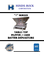
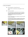
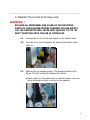
I. INTRODUCTION A. Depositor Overview The Hinds-Bock "T" Series Muffin/Cake depositors are designed to accurately scale and deposit slack to heavy muffin and cake batters into bakery pans from 15 to 26 inches wide. These air powered depositors are available in two basic widths: The "NT" series machines with 3, 4, or 5 pistons are designed for 15" to 18" wide pans. The "WT" series machines with 4, 5 , 6 , or 7 pistons are designed for 23" to 26" pans. Figures I.1-I.4 identify the basic parts of the machines. The volume of the deposit per piston can be adjusted from 2 to 10 ounces using the hand wheel at the front of the depositor. Different pan cavity centerlines are accommodated by changing the product valve. Product valves are also available to gang pistons together for larger deposits, or to use fewer than the supplied number of pistons, thus allowing a wider range of pan configurations to be run. To run the machine, the operator places the mixed batter into the hopper of the depositor, and positions the pan under the discharge ports. At rest, the product valve under the hopper is rotated to open the channels from the hopper to the product cylinders, and the product pistons are at the front of the product cylinders. When the operator depresses the palm button at the front left side of the machine the product pistons move backward to draw batter into the product cylinders (scaling). After the pistons reach their rear stop, the product valve rotates to open the channels from the product cylinders to the discharge ports, and the pistons move forward to deposit the batter into the pan pockets. The product valve then rotates back to its original position ready for another scaling stroke. 2 HINDS-BOCK CORPORATION 1 3 4 5 6 B. Table of Contents I. INTRODUCTION A. Depositor Overview B. Table of Contents C. Safety Warnings and Cautions , II. STARTUP A. Unpack the Depositor B. Install the Depositor C. Set the Correct Air Pressure D. Clean and Sanitize the Depositor III. OPERATING PROCEDURES A. Daily Maintenance Checks B. Sanitize the Depositor C. Run the Depositor D. Clean the Depositor E. Reassemble the Depositor IV. MAINTENANCE INFORMATION A. Pneumatic Operation Sequence B. Trouble-Shooting C. Parts List and Illustrations D. Warranty 7 _____________________________________________________________ C. Safety Warnings and Cautions Safety Warnings: , 1. Do not exceed 85 psi air supply pressure to the depositor. 2. Do not insert fingers, hands, tools, etc. into the product valve outlet ports. 3. Shut off the yellow air lock out valve before connecting air supply to the machine. 8 _____________________________________________________________ C. Safety Warnings and Cautions cont. 4. Make sure personnel are clear of the rotating parts of the depositor before turning the lock out valve on. 5. Disconnect the air supply line at the lock out valve when performing maintenance on the machine. CAUTIONS: , 1. Do not use HOT water to clean the depositor. Hot water can cause the acetyl product valve and pistons to swell making disassembly for cleaning difficult. 2. Do not use CHLORINATED cleaning or sanitizing chemicals on the depositor. Chlorinated materials can damage. 9 _____________________________________________________________ II. STARTUP A. Unpack the Depositor A.1. Inspect the shipping crate. If there appears to be any damage, contact the freight company immediately. Be sure you can give a very specific description of the damage. A photo of the damaged crate can be of assistance in helping you to recover on damage claims. A.2. Unpack the depositor. Use the packing list supplied to check that all the parts have been received. If any parts are missing, contact Hinds-Bock at 1-425-885-1183 to arrange for a replacement. 10 ______________________________________________________ B. Set up the Depositor B.1. Move the depositor to the desired work site. Usually this will be a work table with a working height of 30 to 36 inches. B.2 Check your air supply. a. You should have an air compressor with at east a 5 horsepower motor and an 80 gallon capacity accumulator tank. The compressed air supplied should be as clean and dry as possible to protect the depositor's pneumatic components. An inline air dryer is recommended. b. The air supply header from the compressor to the work site should be at least 1 inch diameter. c. The drop line from the header to the depositor should be at least 3/8 inch inside diameter and be no longer than 15 feet. This drop line should have a appropriate female quick disconnect fitting at the depositor end. 11 _____________________________________________________________ C. Establish The Correct Air Pressure WARNING: , THE AIR SUPPLY PRESSURE TO THE DEPOSITOR SHOULD NOT EXCEED 85 PSI. WARNING: , MAKE SURE THE YELLOW AIR LINE LOCKOUT VALVE IS IN THE OFF POSITION (LEVER DOWN) BEFORE CONNECTING THE AIR SUPPLY TO THE DEPOSITOR. 12 _____________________________________________________________ C. Establish The Correct Air Pressure cont. WARNING: , BEFORE TURNING THE AIR ON TO THE DEPOSITOR CHECK TO BE SURE THAT THE: 6. PISTONS ARE CONNECTED TO THE STRONGBACK. 7. MAIN AIR CYLINDER IS CONNECTED TO THE PIVOT ARM ASSEMBLY 8. PRODUCT VALVE AIR CYLINDER CLEVIS IS CONNECTED TO THE PRODUCT VALVE ARM. 13 _____________________________________________________________ C. Establish The Correct Air Pressure cont. WARNING: , BE SURE ALL PERSONNEL ARE CLEAR OF THE ROTATING PARTS OF THE MACHINE BEFORE TURNING THE AIR SUPPLY ON. THE DEPOSITOR WILL MOVE VERY QUICKLY TO ITS "AT REST" POSITION ONCE THE AIR IS TURNED ON. C.1. Connect the air line to the male nipple on the lockout valve. C.2. Turn the air on to the depositor by pushing the lockout valve lever up. C.3. Observe the air pressure gauge. The pressure should be 80 85 psi. If it isn't, set the air pressure as follows: a. Reach under the Pneumatics cover or carefully remove cover and lift up the black lock collar on the top of the regulator. 14 _____________________________________________________________ C. Establish The Correct Air Pressure cont. b. Turn the collar to adjust the air pressure to the desired range. c. Push the collar down to lock it. 15 _____________________________________________________________ D. Clean and Sanitize the Depositor We recommend that you clean and sanitize the machine prior to running product. The depositor is shipped fully assembled and lubricated. During packing, shipping, and unpacking, dust or dirt may accumulate on the machine which could affect product quality. The procedures for cleaning and sanitizing are part of the normal operating procedures for the machine and are included in Section III. of this manual. 16 _____________________________________________________________ III. OPERATING PROCEDURES A. Daily Maintenance Checks A.1. Drain the air filter bowl. This bowl will normally collect water that condenses in the air supply line between the compressor and the machine. a. Shut off the lockout valve. b. Rotate the small wing valve at the bottom of the filter bowl to open it. The water will drain out. c. Close the wing valve only finger-tight. A.2. Check to be sure that the machine is properly assembled. Normally the machine will be cleaned at the end of use each day. It should be relubricated and reassembled after cleaning to ensure that all parts are returned to the machine and that it is left ready for sanitizing immediately before running product the next day. a. Check that the pistons are all installed and connected to the strongback with the 3/16 inch clevis pins. 17 _____________________________________________________________ A. Daily Maintenance Checks cont. A.2. Check to be sure that the machine is properly assembled cont.. b. Check that the main air cylinder is connected to the pivot arm with the 3/8 inch clevis pin and hairpin clip. c. Check that the product valve cylinder rod clevis is connected to the product valve arm with the 3/8 inch clevis pin and hairpin clip. 18 _____________________________________________________________ A. Daily Maintenance Checks cont. A.3. Check the air pressure a. Turn the lock out valve on. b. Observe the air pressure. It should be 80 - 85 psi. if not, reset it as described in Section II C.4. 19 _____________________________________________________________ B. Sanitize the Depositor B.1. Slow the main air cylinder speed prior to putting sanitizer olution into the hopper by turning the speed control valve. B.2. Install the buspan under the head. a. Put the pan guides into the top set of holes with the flat side of the angle up and the spacers on the outside of the side plates so that the guides are as wide apart as possible. b. Slide the buspan under the head to catch the solution in the next steps. B.3. Turn the lock out valve on to get the depositor in the at rest position. B.4. Prepare approximately four gallons of sanitizer solution. a. Put 4 gallons of lukewarm water into a bucket. b. Add 1 ounce of Klenzade® Ster Bac Quaternary Ammonium Concentrate *(or equivalent Quaternary Ammonium Sanitizer) to the water. This will yield a residual concentration of 200 ppm as required to meet Federal guidelines for sanitizing this type of equipment. * order from Klenzade at 1-800-392-3392 CAUTION: , DO NOT USE CHLORINATED SANITIZER WITH THIS EQUIPMENT. THEY COULD RESULT IN DAMAGE TO THE PROTECTIVE FINISH OF THE HEAD!! 20 _____________________________________________________________ B. Sanitize the Depositor cont. B.5. Pour the sanitizer solution into the hopper of depositor and swirl the solution up onto the hopper walls to ensure that they have been exposed to the solution. B.6. Adjust the piston stop position for approximately 10 ounces so that sanitizer will be exposed to the full product cylinder length. B.7. Cycle the machine slowly to run the sanitizer through the machine so that the solution is in contact with the food path for at least 1 minute. B.8. Discard the used sanitizer, and reset the deposit volume and the speed control to the desired levels. 21 _____________________________________________________________ C. Run the Depositor C.1 Set the Pan Guides. The pan guides are adjustable up and down and in and out to provide for different width pans and for the cleaning buspan which is supplied with the depositor. a. To adjust the guides in/out: each of the 4 guide locking bolts is supplied with two plastic spacers. These spacers are 1/2 inch and 1 inch long so that each guide can be adjusted for 1/2 inch increments of pan width. Both spacers are intended to be used with each bolt; either inside the side plate to move the guide in, or outside the side plate to take up the bolt length so the locking knobs don't have to be turned so far. When running normal 18" wide pans the 1/2 inch spacer is on the inside and the 1 inch spacer is on the out side. b. To adjust the guides up/down: the guide bolts are placed through one of the four sets of 1 inch spaced holes on the side plates. The guides can also be turned over to provide additional height positions. We recommend that the guides be positioned in either the top or second set of holes when running muffins to give the best deposit shape and targeting accuracy. C.2 Run the Depositor. a. Put mixed batter into the hopper of the depositor. b. Position the pan under the discharge port. 22 _____________________________________________________________ c. Depress and release the hand lever at the left side of the machine. If you lock the lever down or hold the lever up, the machine will continue to cycle. d. We recommend that you start with the machine running somewhat slowly to "get the hang" of positioning the pan and moving it between cycles. With a little experience you'll be able to run at top cylinder deposit speed while holding the button down. C.3. Set the Deposit Volume. The deposit volume required varies with the density of the batter being run. For instance, blueberry muffin batter is lighter than bran muffin batter per equivalent volume. Since the depositor accurately scales the same volume of batter on each stroke the stroke stop may need to be reset when batter flavors are changed. To change the stroke volume: a. Loosen the stroke stop screw locking knob. 23 _____________________________________________________________ b. Turn the hand wheel at the front of the depositor. A reference scale is provided on the top of the stroke adjustment mechanism to aid in resetting the volume for each mix. c. Re tighten the locking knob after completing the adjustment. C.4. Set the Depositor Speed. a. Turn the speed control valve in to slow down the piston speed when using water or cleaning solution in the hopper to avoid splashing. b. Turn the speed control all the way out when running batters. (clockwise – slow) (counterclockwise – fast) 24 _____________________________________________________________ D. Clean the Depositor D.1. Pre clean the hopper. a. Scrape the batter off the hopper walls to the bottom of the hopper. b. Put a sheet pan under the machine and cycle the excess batter out of the machine. Discard this batter. c. Position the pan guides to hold the buspan. Put the pan guides into the top set of holes with the flat side of the angle up and the spacers on the outside of the side plates so that the guide surfaces are as wide apart as possible. d. Put the buspan under the head to catch the cleaning solution in the next step. e. Turn the speed control in to slow down the main air cylinder speed to avoid splashing in the next step. D.2. Clean the Hopper. a. Put approximately 2 gallons of LUKEWARM water into the hopper with about a teaspoon of Dawn® or equivalent grease dissolving liquid dish washing detergent. b. Swirl and scrub the hopper walls with a scrub brush or sponge to remove all residual batter. c. Cycle this solution through the depositor to flush out residual batter. Discard the dirty water and replace the buspan under the head. d. Repeat steps D.2. and D.3. with clean lukewarm water to completely clean the hopper. 25 _____________________________________________________________ WARNING:, SHUT OFF THE LOCKOUT VALVE AND DISCONNECT THE AIR LINE. D.3. Disconnect the Product Valve air cylinder by removing the hairpin clip and clevis pin that holds the clevis to the product valve arm. D.4. Rotate the product valve to the discharge position. D.5. Remove the Pistons. a. Pull the clevis pins from the strong back. 26 _____________________________________________________________ D.5. Remove the Pistons. b. Pull the strong back toward the rear of the depositor. The piston rods will slip out of the strong back as you do this. Replace the 3/16 inch clevis pins in the strongback so you won't misplace them. c. While pulling on the piston rods rock them up and down and they will "walk" out the back of the product cylinders. d. Place the pistons into the buspan so they can be taken to the cleanup sink. D.6. Remove the Product Valve. a. Lift the valve retainer bar out of the slot in the right end of the product valve and pull on the product valve arm to extract the product valve out the left side of the depositor. b. Place the Product valve in the buspan to transport it to the sink for clean up. _____________________________________________________________ 27 D.7. Finish Cleaning The Head and Splash Zone. a. Using a sponge or rag and mild detergent solution, clean any residual batter from the product cylinders, the product valve bore, the discharge area, and the underside of the head. Rinse with clean water. b. Remove the pan guides and place them into the buspan to be cleaned at the sink. c. Clean the side plates and cross members with clean detergent solution and rinse with clean water. Allow to air dry. 28 _____________________________________________________________ D.8. Clean the Pistons: a. Remove the O rings from the pistons using the O ring removal tool supplied with the depositor. b. Using only LUKEWARM cleaning solution, scrub the pistons and the O ring grooves to remove any residual batter. c. Clean the O rings in the same manner. D.9. Clean The Product Valve. a. Remove the O rings with the removal tool. b. Using only LUKEWARM cleaning solution scrub the product valve to remove any residual batter. Rinse with clean water and set aside on a clean surface to air dry. c. Clean the O rings in the same manner. D.10. Clean the Pan Guides. 29 _____________________________________________________________ E. Re-assemble the Depositor The depositor is re lubricated with Petrol-Gel® as it is reassembled. E.1. Inspect the O rings. O rings with nicks, flat or worn spots that might cause leaking should be replaced. E.2. Reinstall the Product Valve. a. Using a pea size dab of Petrol-Gel® for each O ring, grease one O ring at a time and roll it into its O ring groove. b. Apply a 2 to 3 inch length of Petrol Gel® to each end of the Product valve bore and spread it around the inside of the bore. c. Apply a 4 to 6 inch length of Petrol Gel® to the outside of the product valve, spread it uniformly over the outside surface of the valve. d. Slide the lubricated product valve into the valve bore from the left of the head. Lift the valve lock bar on the right side of the head and position it into the slot on the right end of the valve. e. Reconnect the product valve air cylinder clevis to the product valve arm with the 3/8 inch clevis pin and hairpin clip. To order Petro-Gel ® from Hinds-bock, please use the following part number: 09192-054 30 _____________________________________________________________ E.3. Reinstall the Product Pistons. a. Working with one piston at a time, use a pea size dab of PetrolGel® to lubricate its O ring, and roll it into the piston groove. b. Squeeze about 1 1/2 inches of Petrol-Gel® into the back end of each cylinder and smear it around inside the cylinder to lubricate it. c. Without setting the piston down after installing its O ring, place the piston into the cylinder with a rocking motion. d. Orient the piston rod so the hole will line up with the hole in the strong back (a clevis pin can be put in the forward hole to assist with this alignment) and slide the piston rod into the strongback. e. Reinstall the 3/16 inch clevis pin to lock the piston rod to the strongback. f. Repeat a. to e. for each piston. E.4. Reinstall the Pan Guides. 31 _____________________________________________________________ IV. MAINTENANCE INFORMATION A. Pneumatic Operation Sequence The Plumbing Diagram and Pneumatic Schematic for the "T" series depositors are shown in Figure (IV.1.) These depositors utilize two air cylinders: a large one(40) at the right side of the depositor that drives the product pistons and a smaller one(34) on the left side of the depositor that rotates the product valve. Pneumatic control valves, located under the pneumatics cover, control the extension and retraction of the cylinder rods to achieve the desired sequence of operation. Air pressure is supplied to the machine through a lockout valve(54) and a combination filter/ regulator(55). The filter traps particulate and water from the supply air and the regulator maintains a constant static air pressure. The air pressure downstream of the regulator is shown on the pressure gauge. Air exhausts from the product valve 4 way valve(56)… 32 _____________________________________________________________ through a simple muffler(57) located behind the filter/regulator on the mounting block manifold. Air exhausts from the piston 4 way valve(58) through a flow control needle valve(52) and muffler. Screwing the needle valve in slows the rate of exhaust thereby slowing the speed of movement of the piston air cylinder rod. The sequence of operation of the machine is illustrated in Figures (IV.1-IV.5.) The pneumatic schematics show the positions of the 4 way valves at each stage in the cycle and the plumbing diagrams show which lines are pressurized and exhausting. Pressurized lines are shown as heavy solid lines. Exhausting lines are shown as heavy dashed lines. At Rest Position: When air is turned on to the machine, the rod ends of both the piston and product valve air cylinders are pressurized causing the cylinder rods to retract. The piston air cylinder rod pulls the pivot arm assembly toward the front of the machine pushing the product pistons to the front of the scaling cylinders in the head. The product valve air cylinder rod pulls the product valve arm toward the back of the machine opening the channel in the product valve from the hopper to the scaling cylinders. 33 _____________________________________________________________ Note that the B pilot of the product valve 4 way valve is pressurized so that the valve is shifted to the position shown in Figure IV.1. Also note that the normally closed port of the palm button(27) is pressurized. Scaling: When the hand lever is momentarily lifted Figure (IV.2), the A pilot of the piston 4 way valve is pressurized causing the 4 way valve to shift and pressurize the back end of the piston air cylinder. The speed of cylinder rod extension is controlled by the needle valve that restricts the rate of exhaust of air from the rod end of the cylinder. As the rod extends it pulls the product pistons back in the scaling cylinders drawing batter in from the hopper (Scaling). The stroke length of the piston air cylinder rod is controlled by the length of the stroke stop tube. The length of the stroke stop tube is adjusted using the hand wheel at the front right corner of the depositor. At the same time that the back end of the piston air cylinder is pressurized, the A pilot of the product valve 4 way valve is pressurized. The valve will not shift until the pressure in the B pilot, which is exhausting through the needle valve, has dropped below 5 psi. Depositing: When the product valve 4 way valve shifts Figure (IV.3) it pressurizes the back end of the product valve air cylinder causing the cylinder rod to extend very quickly, rotating the product valve to open the discharge ports to the scaling cylinders. The shift of the product valve 4 way valve also pressurizes the B pilot of the piston 4 way valve causing it to shift quickly Figure (IV.4), pressurizing the rod end of the piston air cylinder and pulling the pistons forward in the scaling cylinders to push the batter through the discharge ports of the product valve into the pan. Cut off and Reset: The shift of the piston 4 way valve also pressurizes the B pilot of the product valve 4 way valve which shifts the valve after the pressure in the A pilot has decayed to less that 5 psi. See Figure (IV.5.) The shift of the product valve 4 way valve pressurizes the rod end of the product valve air cylinder causing the product valve to rotate quickly to cut off the batter cleanly and to set the product valve in position for the start of a new scaling cycle. The normally closed port of the hand lever valve is also re-pressurized ready to initiate a new cycle once the lever is actuated. See Figure (IV.1.) If the hand lever is held up, the machine will simply continue to repeat the cycle. The valve can be locked in the down position for continuous cycling. 34 35 36 37 38 39 HINDS-BOCK MUFFIN DEPOSITOR TROUBLESHOOTING GUIDE Models 4P-08NT, 5P-08WT, 6P-08WT Problem: Customer calls and says muffin depositor is no longer accurate, that weights are off all the way across the 3 or 4 cavity pan. Solution: Check air pressure. Machine should hold 80-90 PSI while depositor is discharging muffin batter. If pressure drops below 80, adjust the regulator by lifting up on the top ring and turning it clockwise, following the direction of the arrow, until air pressure stays above 80 PSI while depositing. If it does not stay above 80 PSI after adjusting the regulator, have the compressor checked and repaired. *Please note: A minimum diameter of 3/8” or 1/2” is required on the supply line from the compressor to the depositor to carry sufficient CFM to the equipment. An in-line air dryer is recommended. Replace the “O”-rings on the four product pistons and long white product valve. If these are worn out, air will bleed past the seals and fill the product-metering cylinder instead of batter, causing weight control problems. Problem: Long white DELRIN product valve will not slide out of the product head after the depositor has been run for a long period of time. Solution: Product valve has been exposed to heat or hot water at temperatures over 75°F for a length of time. This has caused the product valve to grow and become out of tolerance; it is now too tight to remove from the product head. Let the machine sit for several hours and the valve should contract to a smaller size. It can then be removed from the machine. If necessary, put cold water and/or ice in the hopper to help contract the valve for removal. Please note: Never wash plastic DELRIN product piston or product valve in anything more than luke-warm water to prevent swelling of the plastic parts. Never beat on product valve with a hammer or tool of any kind to remove it from the machine if it is stuck; the valve may crack or the product head may be damaged. 40 TROUBLESHOOTING GUIDE (continue) Problem: White DELRIN product valve will not go into the product head. Solution: Product valve has been subjected to hot water or heat and has grown out of tolerance. It must be returned to Hinds-Bock for re-machining or replacement. Problem: Clevis worn. Solution: Replace 41 ORIFICE INSTALLATION PROCEDURES FOR 5P-08WT TABLETOP DEPOSITOR. The following procedures have to be taken in order to install the supplied orifices. The function of the orifices is to make sure that the pilot air signals are given in the right order so the product valve and the piston rod cylinder are operating in sequence with each other. Supplied airlines with orifices installed: Airline # 1 HINDS-BOCK PART # Orifice .0071”/ .18mm 09155-420 Air-connector 10/32x¼ ” 09193-085 Blue airline tubing ¼ ” 09192-595 White airline tubing ¼ ” 09192-598 Airline # 2 Airline # 1: Has a white colored 3-inch piece of airline on one side of the orifice and a blue colored 8-inch piece of airline on the other side. Airline # 2: Has only a white colored 2-inch piece of airline on one side of the orifice. Procedure to remove and install supplied components: 1: Disconnect the air supply to the depositor, by shutting off the manual dump valve at the air inlet. 42 2: Remove the cover from the pneumatic components by tilting the cover slightly upwards and lifting it up over the pressure gauge and speed control valve. Shown before modification Airline # 2 Airline # 1 3: Locate the 2 airlines on top of the pneumatic stack valves. Shown after modification 4: Remove airline # 1 by pushing the airline into the connector and holding the snap ring back with your fingers. 5: Install the supplied airline # 1 as follows: Insert the end of the white colored 3-inch of the airline into the top of the stack valve and the end of the blue colored 8-inch of the airline into the bottom of the valve. 6: Remove airline # 2 and shorten the airline approx. 2 ½ inches. 7: Install the supplied airline # 2 as follows: Insert the end of the white colored 2-inch of the airline into the top of the stack valve. Insert the end of the blue airline that you shortened into the end of the orifice that has no airline installed. 8: 9: 10: Reinstall the cover over the pneumatic components. Turn the supply air back on. Test the depositing cycle by pressing the start lever on front of the depositor. 43 _____________________________________________________ C. Parts Lists and Illustrations 44 MECHANICAL PARTS LISTING 5P-08WT TABLE TOP BATTER DEPOSITOR / WIDE TRAY 09443A-004 REV: 04.29.2002 FIGURE: IV.6 MECHANICAL PARTS LISTING 5P-08WT TABLE TOP BATTER DEPOSITOR / WIDE TRAY 09443A-004 ITEM No. 01 02 03 04 05 06 07 08 09 10 11 12 13 14 15 17 18 19 20 21 22 23 24 27 28 29 30 31 32 33 34 35 36 38 39 40 41 42 43 44 45 46 47 49 50 51 55 59 66 67 68 69 71 73 NOTE N N N N L L, N A L L L, N N L, N QTY 1 1 1 1 5 5 2 1 1 1 2 2 2 1 5 1 1 5 2 4 4 4 1 1 1 2 2 1 1 5 1 1 1 1 1 1 1 1 1 1 1 1 1 1 1 1 2 1 1 1 1 1 1 1 PART No. 09443-048 09443-060 09443-046 09443-045 09443-040 09180-670 09180-693 09443-068 09443-001 09443-042 09443-044 09443-012 09443-013 09443-043 09190-607 09443-028 09443-041 09443-021 09443-017 09443-049 09443-050 09190-620 09192-007 09155-473 09443-005 09190-638 09190-637 09155-115 09443-024 09443-007 09155-870 09443-037 09443-018 09443-019 00119-001 09155-871 09190-124 09190-622 09443-025 09443-039 09443-008 09443-009 09443-053 09190-533 09443-011 09443-187 09443-014 09190-327 09443-052 09192-009 HB040-16--00SS 09443-106 09155-678 HB060-12C-00SS PART DESCRIPTION HOPPER w/BASE WIDE GASKET HOPPER HEAD PROD WIDE VALVE PRODUCT 5 PORT 4-3/8”C/L PISTON DEL ORING BUNA (PRODUCT PISTONS) ORING BUNA (PRODUCT VALVE) PLATE SIDE ALUM (HAND SWITCH) PLATE SIDE ALUM ARM PIVOT WIDE SPACER BAR ALUM BRG DEL BRG DEL STRONGBACK PIN CLEVIS 3/16"Dx1-1/2"L SS WASHER PIN PIVOT ARM ROD PISTON RACK TRAY WIDE PAN 2-5/8” SPACER SHORT WIDE PAN SPACER LONG 1” LG (WIDE PAN) KNOB HAND 2-1/8"D 3/8"x1"DP ELBOW LEVER VALVE BAR PRODUCT VALVE PIN CLEVIS 3/8"Dx1"L SS PIN COTTER HAIRPIN 3/8"-7/16" CLEVIS 1/2"-20 THREAD PLATED CLEVIS S.S. SPACER AIR CYLINDER SPACER CYL MNT BRACKET SS MNT CYL LOCK BAR STD AIR CYLINDER HANDLE 1/4-20 NC WHEEL HAND STRK ADJ 3/4"-10THR BUMPER URETHANE PLATE THRUST STRK STOP ROD STRK ADJ. BRONZE STOP STRK TUBE PLUG LOCK NYLON KNOB HAND 5/16"NCx3/4"L SS TUBE PLASTIC COVER PNEUMATICS BOLT MOD. 5/8"-11NC PIN HITCH .125"D 7/16" SHAFT BOLT MOD. 3/8"-16x2" ELBOW WASHER FLAT 1" COVER HAND VALVE LEVER MUFFLER NUT ACORN 3/4-10NC THREAD REV: 04.29.2002 FIGURE: IV.6 MECHANICAL PARTS LISTING 5P-08WT TABLE TOP BATTER DEPOSITOR / WIDE TRAY 09443A-004 ITEM No. NOTE QTY PART No. 74 76 77 K 1 1 1 HB010-04C-06SS 09443-141 PD165-001 BOLT HXHD 1/4-20x3/4L GUARD HAND/FINGER PROTECT PNEUMATIC ASSY 2 4 2 1 1 1 1 2 2 1 5 1 2 1 1 1 1 1 1 1 1 4 1 1 09155-420 09193-085 09181-843 09215-002 09443-056 09443-057 09443-061 09443-062 HB010-03F-12SS HB010-04C-07SS HB010-06C-22SS HB010-10F-10SS HB060-03F-00SS LAB002 LAB003 LAB004 LAB023 LAB025 LAB026 LAB033 LAB027 LAB046 LAB168 LAB176 CHOKE .0071”D .18mm 10-32 FXD CONN M T-M-UNF 1/4x10-32 CAP HOLE PLUG 3/8" PLASTIC CAP CYL END DEL 1-3/8-12 THRD COVER NOSE COVER THREAD KNOB BOOT FITTING 1/4" BOOT CLEVIS BOLT HXHD 10-32x1-1/2L BOLT HXHD 1/4-20x7/8L BOLT HXHD 3/8-16x2-3/4L BOLT HXHD 5/8-18x1-1/4L NUT ACORN 10-32NF THREAD PLATE NAME SMALL LABEL DANGER 4" x 7" LABEL BISSC CERTIFIED SCALE OVERLAY SELF ADHESIVE LABEL SPCL "DANGER" 3.5x3-9/16 LABEL DAILY MAINT LABEL CAUTION KEEP HANDS OUT NSF MARK LABEL DANGER/PELIGRO HOPPER LABEL - MUFFIN MACHINE OPER. LABEL KEEP FINGERS.ENG SPANISH FIGURE: IV.6 PART DESCRIPTION ITEMS NOT SHOWN ------------------------- M M M M M M M NOTES: A. K. L M. N. PRODUCT VALVE #04 INCLUDES A PRODUCT VALVE BAR #05. KEEP THIS GUARD IN PLACE AT ALL TIMES. DISCONNECT AIR BEFORE SANITIZING MACHINE. NOTE SAFETY STICKERS ON MACHINE. THIS ITEM NOT USED WHEN PAN OILER OPTION ADDED TO MACHINE. PART OF PD165-001 (SHOWN FOR REFERENCE ONLY ON THIS DRAWING. NSF REQUIRED. NOT REQUIRED WHEN THE SAFTEY TRAY/SCALE ASSY’S USED. MECHANICAL PARTS LISTING 5P-08WT TABLE TOP BATTER DEPOSITOR / WIDE TRAY 09443A-004 PNEUMATICS PARTS LISTING MULTI PISTON TABLE TOP BATTER DEPOSITOR PD165-001 (EXPLODED PARTS DIAGRAM) FIGURE: IV.1, IV.6 & IV.7 3 PNEUMATICS PARTS LISTING MULTI PISTON TABLE TOP BATTER DEPOSITOR PD165-001 FIGURE: IV.1, IV.6 & IV.7 4 PNEUMATICS PARTS LISTING MULTI PISTON TABLE TOP BATTER DEPOSITOR PD165-001 ITEM # NOTE QTY 24 27 34 40 52 53 54 56 57 58 67 70 71 78 79 80 81 82 83 84 85 C A A A 6 1 1 1 1 1 1 1 2 1 4 1 1 1 1 1 1 1 1 1 1 09192-007 09155-473 09155-870 09155-871 09155-886 09155-888 09155-726 09155-873 09155-344 09155-873 09192-009 09155-283 09155-678 09192-493 09192-543 09155-876 09192-579 09192-165 09192-064 09192-496 09192-496 ELBOW MALE T-M-NPT 1/4”x1/8” VALVE, LEVER CYLINDER, AIR 1-1/2”Bx4”s w/BUMPERS CYLINDER, AIR 2-1/2”Bx5”s w/BUMPERS FLOW CONTROL GAUGE AIR 1/4”NPT VALVE LOCKOUT 3/8”NPT SOL. VALVE 4-WAY MUFFLER 3/8” SOL. VALVE 4-WAY ELBOW MALE T-M-NPT ¼”x¼” REGULATOR 3/8”NPT MUFFLER 1/4” FLAT/LOW PROFILE ELBOW STREET 90D 3/8”NPT FITTING SWIVEL 3/8”NPT END PLATE CONNECTOR NIPPLE PIPE 3/8”NPT BRASS CONNECTOR NIPPLE PIPE 3/8”NPT S TEE M RUN T-T-M NPT ¼”x¼” PIPE PLUG ¼”NPT HOLLOW HEX PIPE PLUG 3/8”NPT HOLLOW HEX 1 1 1 2 09155-874 09155-875 09155-574 09155-420 END PLATE KIT ISOLATION KIT PIPE PLUG CHOKE .0071”D 18mm C C B B B A C A PART # FIGURE: IV.1, IV.6 & IV.7 DESCRIPTION ITEMS NOT SHOWN ----NOTES: NOTES: A. B. C. D. PARTS SHOWN ON FIGURE IV.6. PARTS SHOWN ON FIGURE IV. PARTS SHOWN BOTH FIGURE IV.6 & IV.7. FOR USE WITH 09443‐125 HOPPER COVER & 09443‐126 HOPPER 5 _____________________________________________________________ D. WARRANTY SELLER WARRANTS EQUIPMENT OF ITS OWN MANUFACTURE TO BE FREE FROM DEFECTS IN MATERIALS AND WORKMANSHIP. THIS WARRANTY EXTENDS ONLY TO THE ORIGINAL BUYER AND IS LIMITED TO REPAIR OR REPLACEMENT F.O.B. SELLER'S FACTORY OF ANY ORIGINAL PART OR COMPONENT MANUFACTURED BY SELLER WHICH IS FOUND BY SELLER TO HAVE BEEN DEFECTIVE AT THE TIME OF SHIPMENT, PROVIDED WRITTEN CLAIM HAS BEEN RECEIVED FROM BUYER WITHIN SIX MONTHS OF SHIPMENT AND SUCH ORIGINAL PART OR COMPONENT IS RETURNED PREPAID TO SELLER. THIS WARRANTY APPLIES ONLY TO THE EQUIPMENT INSTALLED AND OPERATED IN ACCORDANCE WITH HINDS‐BOCK CORPORATION'S RECOMMENDATIONS AND SUCH WARRANTY DOES NOT APPLY WHERE HINDS‐BOCK CORPORATION DETERMINES THAT ANY CLAIMED DEFECT AROSE AS A RESULT OF PURCHASER'S MISUSE, NEGLECT, IMPROPER INSTALLATION, REPAIR, ALTERATION, ACCIDENT OR NORMAL WEAR AND TEAR WITH RESPECT TO ANY EQUIPMENT DELIVERED HEREUNDER. WITH RESPECT TO THE EQUIPMENT, MATERIALS, PARTS AND ACCESSORIES MANUFACTURED BY OTHERS, SELLER WILL UNDERTAKE TO OBTAIN FOR BUYER THE FULL BENEFIT OF THE MANUFACTURER'S WARRANTIES. SELLER WILL NOT BE LIABLE FOR ANY LOSS OF PROFIT, LOSS BY REASON OF PLANT SHUTDOWN, NON‐OPERATIONAL OR INCREASED EXPENSE OF OPERATION, LOSS OF PRODUCT OR MATERIALS, OR OTHER SPECIAL OR CONSEQUENTIAL LOSS OR DAMAGE OF ANY NATURE, AND ALL CLAIMS FOR SUCH LOSS OR DAMAGE ARE EXPRESSLY WAIVED BY BUYER. THIS WARRANTY IS IN LIEU OF ALL OTHER WARRANTIES, EXPRESSED OR IMPLIED HINDS-BOCK CORPORATION Hinds‐Bock Corporation 2122 ‐ 222 Street S.E. ‐ Bothell, WA 98021 ‐ USA nd TOLL FREE: 1.877.292.5715 ‐ 1.888.557.7881 (PARTS) TEL 425.885.1183 FAX 425.885.1492 FAX 425.897.4110 (PARTS) WEBSITE: hinds‐bock.com ‐ E‐MAIL: info@hinds‐bock.com 35